


If you want to make any IoT device then Blynk is a popular Internet of Things (IoT) platform that allows you to control hardware remotely through smartphones or tablets. It provides a user-friendly drag-and-drop interface to simplify the creation of customized interfaces for designing and controlling various IoT devices and projects. Blynk supports many different types of development boards and different types of connection types such as Ethernet, WiFi, GSM, and Satellite. It facilitates real-time data visualization, remote monitoring, and interactive automation.
In this article, we will learn to set up and use the Blynk IoT App to control our devices. Previously we have also learnt how to use ESP8266 with Blynk App, but recently Blkynk app has been updated to blynk2.0 so this article provides the latest steps on how to use the new Blynk IoT platform. You can also check out our previous Blynk IoT Projects if you need more project ideas.
Setting up NodeMCU for Blynk App
To test our new Blynk IoT app we will be controlling some LEDs connected to the node MCU from the blynk mobile application. So lets start by setting up our NodeMCU board for this tutorial
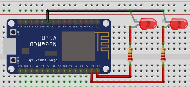
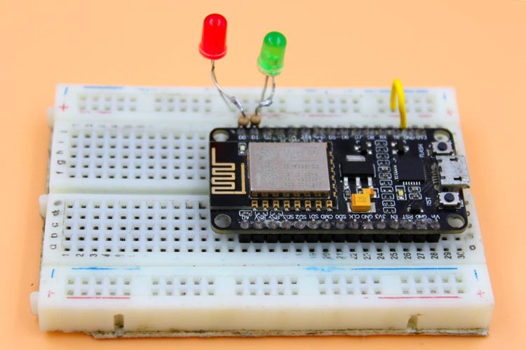
Connect LEDs to the NodeMCU as shown in the above schematic. One LED is connected to GPIO D0, and the other one is to GPIO D2. Don’t forgot to put a resistor in between GPIO pin and positive terminal. It will protect our LED from over voltage. Once the connections are done you set-up will look something like below
Setup Blynk 2.0 App
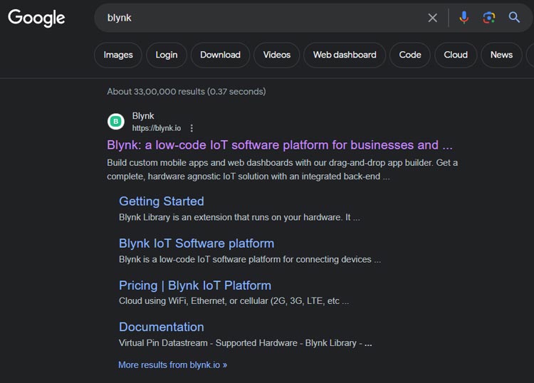
Step 1: Go to the Blynk website and click the "Sign Up" button. Enter your email address and create a password.
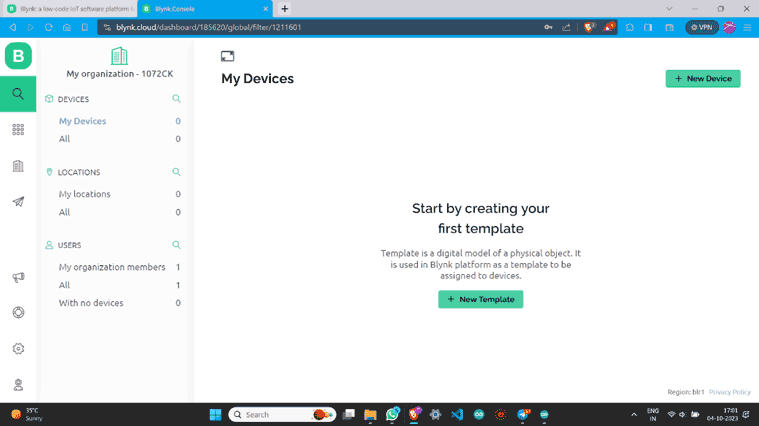
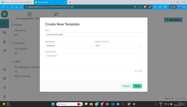
Step 2: Once you have signed up on the Blynk and logged in, tap the "+ New Template" button to create a new template.
Step 3: Name the template, select the Development Board, set WiFi as the connection type and then save this template.
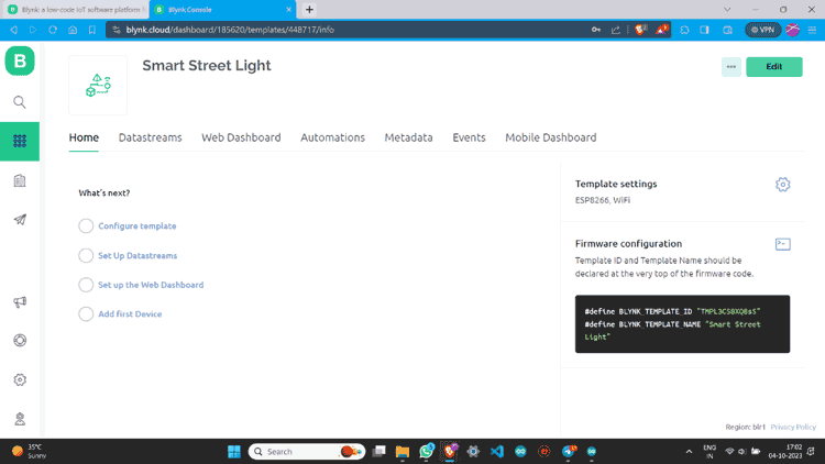
Step 4: Once a new template is created you will see the below screen on your blynk account.
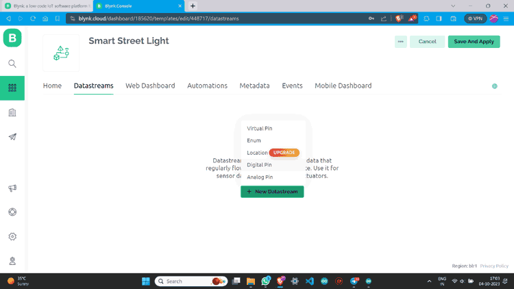
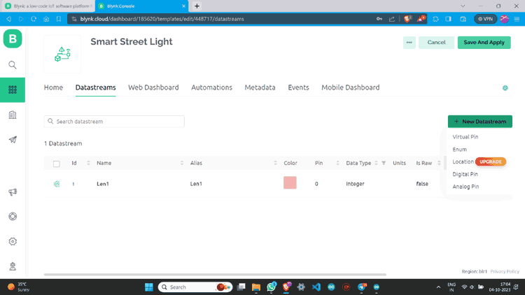
Step 5: Go to Datastreams and click on “+ New Datastream”. Then Choose “Digital Pin”.
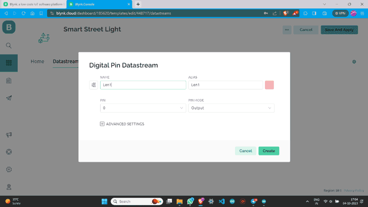
Step 6: Name Datastream and select pin. Assign it’s PIN MODE as Output and Create.
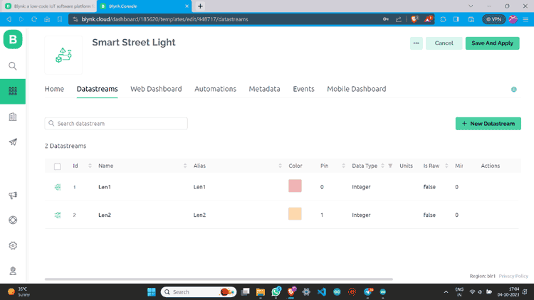
Step 7: Once a datastream is created on the blynk website, it will look something like this below
Step 8: I have made one more data stream with the same values.
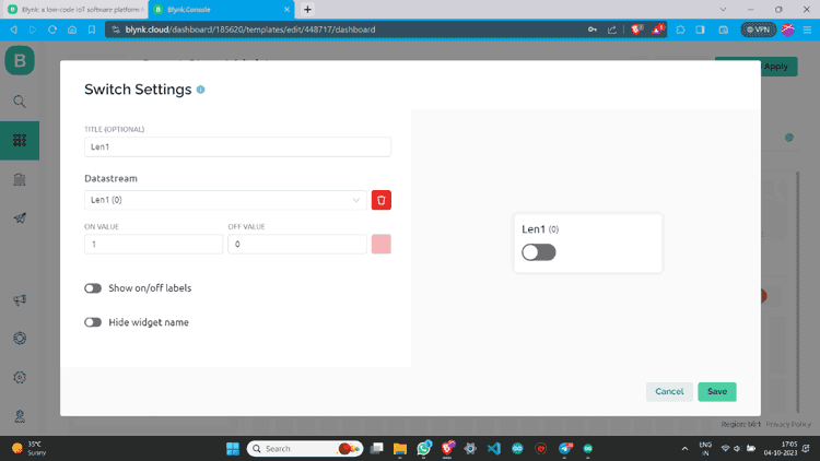
Step 9: Go to “Web Dashboard” and add Switch widgets.
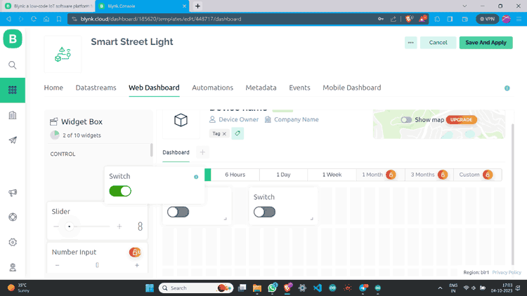
Step 10: Click on the Gear button, give values according to your choice, and save.
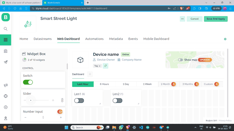
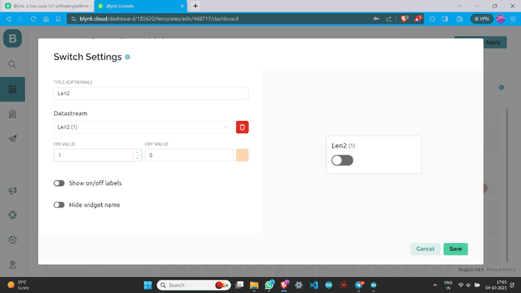
Step 11: I have made one more switch and assigned all values.
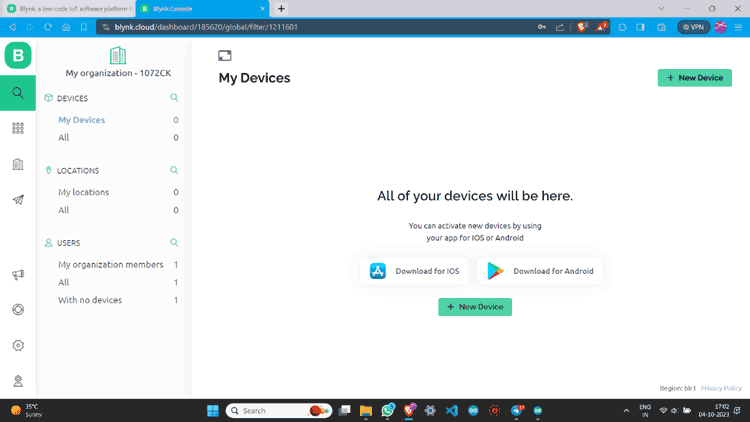
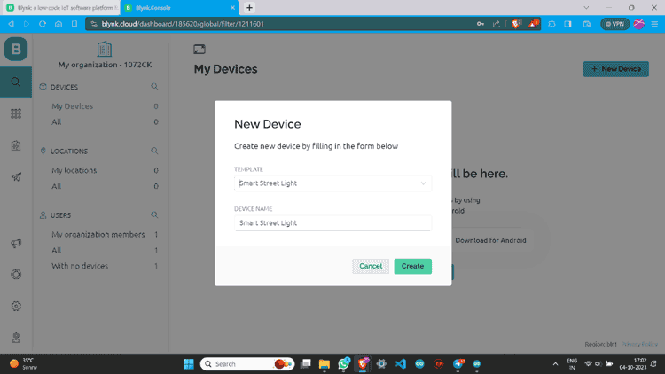
Step 12: Go to the lens icon and click on “+ New Device”.
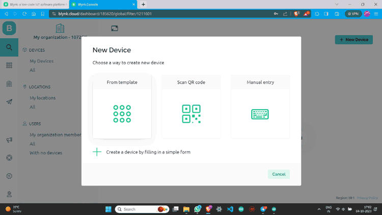
Step 13: Click “From template”, select the template, and create.
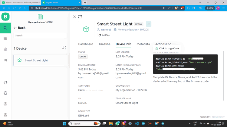
Step 13: Now you can see the device. Click on “Device Info” and copy the Auth Token.
Blynk 2.0 Application Setup
Now after Web setup, we have to make a Mobile App Interface so that we can able to control it from any Android or IOS
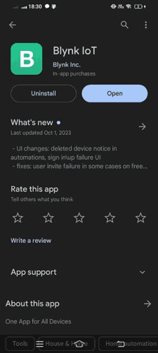
Step 1: Download the Blynk app.
The Blynk app is available for both IOS and Android devices. You can download the app from the App Store or Google Play.
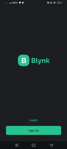
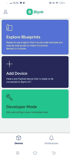
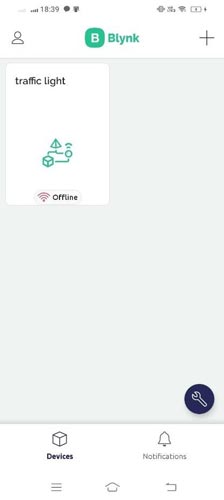
Step 2: Now open the Blynk IOT app and Log in with the credentials.
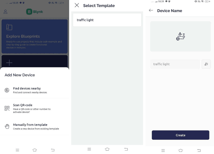
Step 3: After logging in click on “Add Device”.
Step 4: Click “Manually from template”, select the device we already created, and then create.
Step 5: Now you are on the dashboard of the device then click on the tool button to enter in Developer Mode.
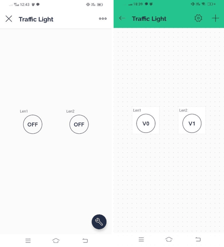
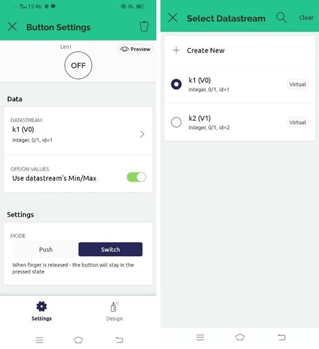
Step 6: Click on the button icons to assign values like Datastream and Mode. You can also change its design and looks.
Step 7: You Have successfully created a device dashboard.
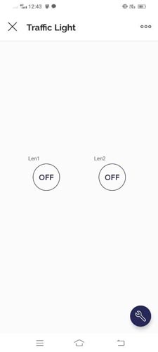
Step 8: You can check the device status also.
Setup Arduino IDE
Now we have to set our Arduino IDE to program the NodeMCU ESP8266 board.
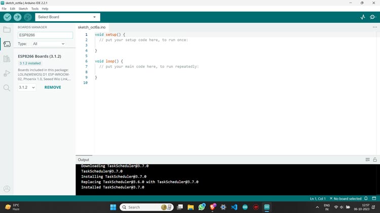
Step 1: In Arduino IDE go to the “BOARDS MANAGER” and install ESP8266.
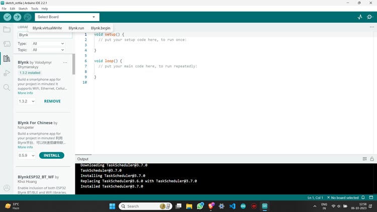
Step 2: Then go to the “LIBRARY MANAGER” and install the Blynk library.
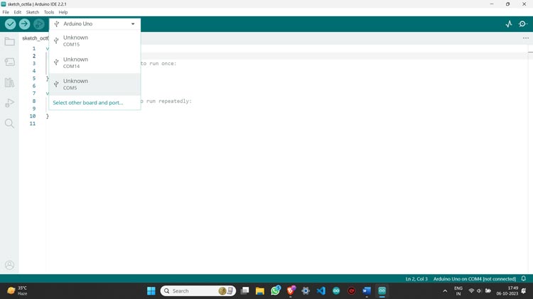
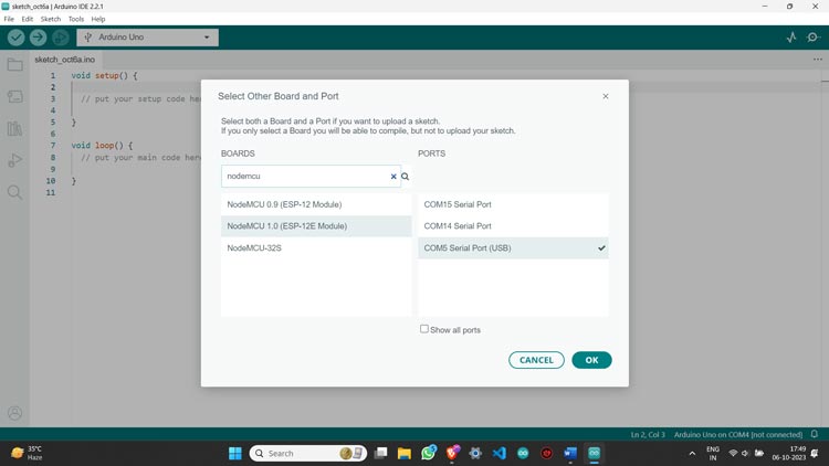
Step 3: Plug your NodeMCU ESP8266 board into the PC using a USB cable and then select your board and port.
Step 5: Your Arduino IDE is now ready to program your board.
Blynk Code for NodeMCU
This code is for controlling two digital pins (D0 and D1) using the Blynk app.
#define BLYNK_TEMPLATE_ID “xxxxxxxxxxxx"
#define BLYNK_TEMPLATE_NAME "xxxx"
#define BLYNK_AUTH_TOKEN "Your Auth Token"
#define BLYNK_PRINT Serial
#include <ESP8266WiFi.h>
#include <BlynkSimpleEsp8266.h>
char auth[] = BLYNK_AUTH_TOKEN;
char ssid[] = "Your SSID";
char pass[] = "Your Password";
// This function is called every time the Virtual Pin 0 state changes
BLYNK_WRITE(V0){
  int value = param.asInt();
  if(value == 1){
    digitalWrite(D0, HIGH);
     Serial.println('1');
  }else{
   digitalWrite(D0, LOW);
    Serial.println('0');
  }
  }
BLYNK_WRITE(V1){
    int value = param.asInt();
  if(value == 1){
    digitalWrite(D1, HIGH);
     Serial.println('1');
  }else{
   digitalWrite(D1, LOW);
    Serial.println('0');
  }
  }
void setup(){
  pinMode(D0, OUTPUT);
  pinMode(D1, OUTPUT);
  Serial.begin(115200);
  Blynk.begin(auth, ssid, pass);
}
void loop(){
  Blynk.run();
}
Blynk 2.0 Arduino Code Explanation
#define BLYNK_TEMPLATE_ID “xxxxxxxxxxxx"
#define BLYNK_TEMPLATE_NAME "xxxx"
#define BLYNK_AUTH_TOKEN "Your Auth Token"
#define BLYNK_PRINT Serial
Here we have defined the Blynk template ID, template name, and authentication token.
Don’t forget to replace "xxxxxxxxxxxx" with your actual template ID, “xxxx” with your template name, and "Your Auth Token" with your Blynk authentication token. You can find it in the “Device info” of the web device dashboard or in the Blynk app.
char ssid[] = "Your SSID";
char pass[] = "Your Password";
Remember to replace "Your SSID" with your WiFi network name and "Your Password" with your WiFi password.
BLYNK_WRITE(V0) {
    // Handles changes in Virtual Pin V0 state
}
BLYNK_WRITE(V1) {
    // Handles changes in Virtual Pin V1 state
}
Inside these functions, the code checks the received value. If the value is 1, it sets the corresponding digital pin (D0 or D1) to HIGH. If the value is 0, it sets the digital pin to LOW.
void setup() {
    pinMode(D0, OUTPUT);
    pinMode(D1, OUTPUT);
    Serial.begin(115200);
    Blynk.begin(auth, ssid, pass);
}
In the setup function, the digital pins D0 and D1 are configured as output pins. Serial communication starts and the board connects to the Blynk server using the provided WiFi credentials and authentication token.
void loop() {
    Blynk.run();
}
The loop function continuously calls Blynk.run(), allowing the Blynk library to process any incoming commands from the Blynk app.
Using Blynk 2.0 on NodeMCU
Now we have learned to add internet control to our devices using the Blynk application. This article covers basic and fundamental steps to start with Blynk 2.0 but it has a lot of features that you can explore and make a lot of projects.
Now that you have learnt how to use the blynk 2.0 app with NodeMCU you can check out our NodeMCU IoT Projects to built more amazing IoT projects using Blynk and ESP8266 NodeMCU.


