


NeoPixel LED Strip Lights are programmable RGB LED strip which can be programmed to generate any desired lighting pattern. NeoPixel can produce multiple colors in any combination and brightness. It consumes less power and can be addressed individually via programming. In this project, we will learn to control the WS2812 NeoPixel LED strips using ESP32 and Blynk application.
Components Required
- 25 LEDs WS2812B NeoPixel LED Strip
- 5V, 2 AMP Power supply
- ESP32 Development board
- Breadboard
- Jumper wires
WS2812 LED Strip Working
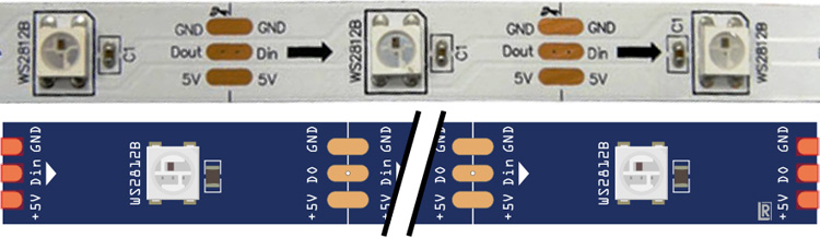
WS2812 LED strips are an addressable Flexible strip which is very useful in adding beautiful lighting effects. These LED Strips are powered by a 5050 RGB LED with a WS2812 LED driver inbuilt within it. Each LED consumes 60mA current and can be powered from a 5V DC supply. It has a single input data pin which can be fed from the digital pins of Micro-controllers.
Features:
- Individually addressable RGB LEDs
- 16.8 million colors per pixel
- Single-wire digital control
- Operating Voltage: 5V DC
- Current Requirement: 60mA per LED
- Flexible LED structure
- 5050 RGB LED with WS2812 driver
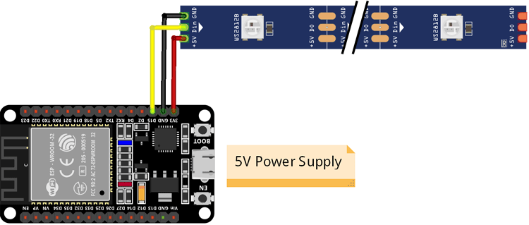
Circuit Diagram
Circuit diagram for WS2812 ESP32 is given below:
![]()
Blynk Application Setup for NeoPixel with ESP32
Blynk is an application that can run over Android and IOS devices to control any IoT devices using our smartphones. We can create our own Graphical user interface to design the IoT application GUI. We previously used Blynk with ESP32 and built many other IoT based projects using Blynk.
Before setup, download the Blynk Application from Google Play store (IOS users can download from Apple Store) and Sign-up using your email id and Password.
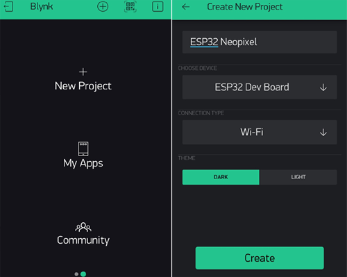
Creating a new Project:
After successful installation, open the application and click on “New Project”. Then it will pop up a new screen, where we need to set the parameters like Project name, board, and connection type. For this project, select the device as “ESP32 Dev Board” and connection type as Wi-Fi and click on “Create”.
After the successful creation of the Project, we will get an Authenticate ID in our registered mail. Save the Authenticate ID for future reference.
Creating the GUI:
Open the project in Blynk, click on the “+” sign where it will show many widgets. In our case, we need an RGB Color Picker which is listed as “zeRGBa” and a Button which will be used for changing the mode of operation in the LED strip.
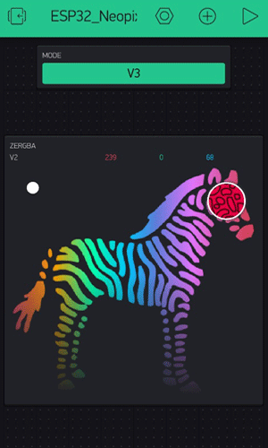
Setting the Parameter in Widgets:
After dragging the widgets to the project, now set its parameters which are used to send the color and mode of control values to ESP32.
Click on ZeRGBa, then we will get a screen named ZeRGBa setting. Then set the Output option to “Merge” and set the pin to “V2” which is shown in the image below. Similarly, in Button settings, set the output pin to “V3” as shown in the figure below.
![]()
Installing ESP32 Board in Arduino IDE
Before uploading the code into ESP32, we need to install the board in Arduino IDE, if you haven’t done it earlier. To install ESP32 board follows the steps below:
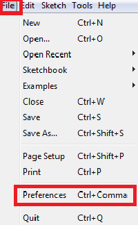
1. Open Arduino IDE, go to File> Preferences
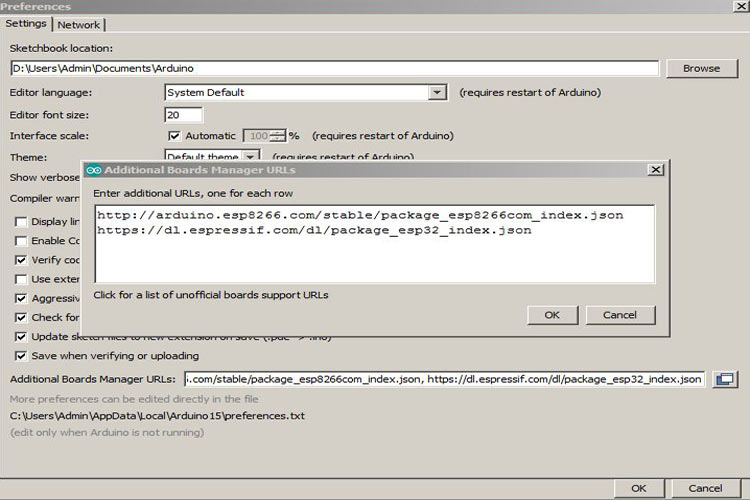
2. Type “https://dl.espressif.com/dl/package_esp32_index.json” in the ‘Additional Board Manager URL’ field and click ‘Ok’. If you already have other URLs in that field, write this by separating it using a comma (“,”).
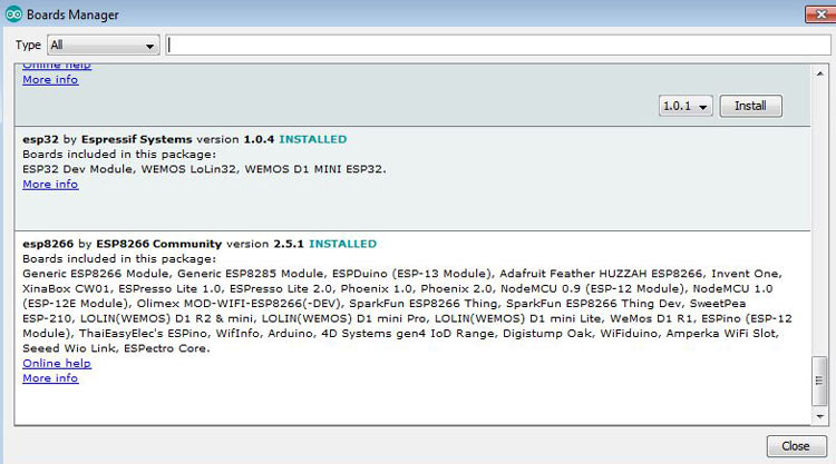
3. Now go to Tools > Board > Boards Manager. In the Boards Manager window, Type ESP32 in the search box, select the latest version of the board ESP32 by espressif systems, and click on install.
4. After installation is complete, go to Tools ->Board -> and select ESP32 Dev Module. Now you can program the ESP32 with Arduino IDE.
Code for ESP32 NeoPixel LED Strip Control
Complete code for ESP32 NeoPixel is given at the end of this tutorial. The step-wise explanation of the code is shown below.
First of all, including all the required libraries to the code. Open Arduino IDE, then go to the tab Sketch and click on the option Include Library-> Manage Libraries. Then search for Blynk in the search box and download and install the Blynk package for ESP32.
Here “Adafruit_NeoPixel.h” is used for controlling the RGB LED strip. For including Adafruit_NeoPixel.h library, download the library from this link and include it using the “Include ZIP Library” option.
#include <WiFi.h>
#include <WiFiClient.h>
#include <BlynkSimpleEsp32.h>
#include <Adafruit_NeoPixel.h>
Then define the number of LEDs which is used in the LED strip and also the PIN number which is used to control the LED parameters.
#define PIN 15
#define NUM 25
After this, declare the NeoPixel strip object where Argument 1 is the number of pixels in the NeoPixel strip, Argument 2 is the ESP32 PIN number used and Argument 3 is Pixel type flags.
Adafruit_NeoPixel pixels = Adafruit_NeoPixel(NUM,PIN, NEO_GRB + NEO_KHZ800);
Then, define the network credentials such as network SSID and password. Write your own network credentials in place of ssid[] and pass a [] array. Inside auth[] array, write the Blynk authenticate ID which we have saved earlier.
char auth[] = "HoLYSq-SGJAafQUQXXXXXXXX";
char ssid[] = "admin";
char pass[] = "12345678";
Inside setup(), Serial communication is initialized using function Serial.begin. Here Blynk is connected using Blynk.begin and NeoPixel LED strip is initialized using pixels.begin().
void setup()
{
  Serial.begin(115200);
  Blynk.begin(auth, ssid, pass);
  pixels.begin();
}
Inside infinite loop (), we have used Blynk.run () which checks for incoming commands from blynk GUI and executes the operations accordingly.
void loop()
{
  Blynk.run();
}
Here BLYNK_WRITE function is written to check for incoming data at V3 and V2 Virtual terminal, then assign them in three different variables. The variable r, g, b here represents the value of Red, Green, and Blue code of the selected color. Then these values are sent to the function static1 which is used for driving the LED strip.
BLYNK_WRITE(V2)
{
r = param[0].asInt();
g = param[1].asInt();
b = param[2].asInt();
if(data==0)
static1(r,g,b);
}
BLYNK_WRITE(V3)
{
data = param.asInt();
Serial.println(data);
if(data==0)
{
  static1(r,g,b);
}
else if(data==1)
{
  animation1();
}
}
Static1 () function is used to drive the LED strip with distinct colors. Here, pixels.setPixelColor is used for driving the LED as per our required color.
void static1(int r, int g, int b)
{
  for(int i=0;i<=NUM;i++)
  {
pixels.setPixelColor(i, pixels.Color(r,g,b));
  pixels.show();
  }
}
Animation1() function is used to run a customized animation using LEDs. Different animations can be made as per the user's choice as shown below.
void animation1()
{
  for(int i=0;i<NUM;i++)
  {
    pixels.setPixelColor(i, pixels.Color(255,0,0));
    pixels.show();
    delay(100);
  }
  for(int i=NUM;i>=0;i--)
  {
    pixels.setPixelColor(i, pixels.Color(0,255,0));
    pixels.show();
    delay(100);
  }
  for(int i=0;i<NUM;i++)
  {
    pixels.setPixelColor(i, pixels.Color(0,255,255));
    pixels.show();
    delay(100);
  }
  for(int i=NUM;i>=0;i--)
  {
    pixels.setPixelColor(i, pixels.Color(255,255,0));
    pixels.show();
    delay(100);
  }
}
Testing NeoPixel with ESP32
After successful completion of hardware connection, upload the complete code in ESP32 and you will find the illuminated NeoPixels according to your program.
![]()
Complete code and a demonstration video for this NeoPixel control using ESP32 are given below.
#include <WiFi.h>
#include <WiFiClient.h>
#include <BlynkSimpleEsp32.h>
#include <Adafruit_NeoPixel.h>
#define PIN 15
#define NUM 25
Adafruit_NeoPixel pixels = Adafruit_NeoPixel(NUM,PIN, NEO_GRB + NEO_KHZ800);
char auth[] = "HoLYSq-Sxxxx";
char ssid[] = "admin";
char pass[] = "12345678";
int r,g,b,data;
void setup()
{
Serial.begin(115200);
Blynk.begin(auth, ssid, pass);
pixels.begin();
}
void loop()
{
Blynk.run();
}
BLYNK_WRITE(V2)
{
r = param[0].asInt();
g = param[1].asInt();
b = param[2].asInt();
if(data==0)
static1(r,g,b);
}
BLYNK_WRITE(V3)
{
data = param.asInt();
Serial.println(data);
if(data==0)
{
static1(r,g,b);
}
else if(data==1)
{
animation1();
}
}
void static1(int r, int g, int b)
{
for(int i=0;i<=NUM;i++)
{
pixels.setPixelColor(i, pixels.Color(r,g,b));
pixels.show();
}
}
void animation1()
{
for(int i=0;i<NUM;i++)
{
pixels.setPixelColor(i, pixels.Color(255,0,0));
pixels.show();
delay(100);
}
for(int i=NUM;i>=0;i--)
{
pixels.setPixelColor(i, pixels.Color(0,255,0));
pixels.show();
delay(100);
}
for(int i=0;i<NUM;i++)
{
pixels.setPixelColor(i, pixels.Color(0,255,255));
pixels.show();
delay(100);
}
for(int i=NUM;i>=0;i--)
{
pixels.setPixelColor(i, pixels.Color(255,255,0));
pixels.show();
delay(100);
}
}


