


Garage doors are too heavy and take a lot of effort to open and close. In this age of IoT where everything is connected to the internet, we should also improve it. Imagine effortlessly opening your garage door with just a tap on your smartphone, that is exactly what we are going to build in this smart garage door IoT project and we will be using an ESP32 development board and Arduino IDE to build this project. Previously we have also built a similar Wi-Fi Garage Door Opener Project using DC motor, you can also check that out if your interested.
Components Required to build IoT Garage Door Opener
-
NodeMCU ESP32
-
2 x Servo Motors (SG90)
-
Power Supply
-
BreadBoard
-
Jumper Wires
We are using a NodeMCU ESP32 board as the microcontroller for this project. It is a very powerful, WiFi-enabled, and very low-cost microcontroller. It is a perfect board for IoT projects. We have 2 Servo motors(SG90) for the lifting mechanism of the IoT garage door. It is a small low-cost servo motor that can rotate from 0 to 180 degrees at an operating voltage of 4.8 to 6V. This 9-gram motor provides up to 1.8 kg-cm torque at 6V. We need a 5V power supply to power the whole setup. You can use a 5V adapter or a power bank. For all the connections we need a breadboard and some Jumper wires. At last, we also need to make a garage and for that we used cardboard and chart papers for it.
Circuit Diagram for IoT Garage Door
Since we have not used any iot garage door sensor, the circuit for this project is very simple. We will just need two servo motors connected to a ESP32 development board like shown the connection diagram below. Also if you are using the ESP32 board for the first time you should check out our ESP32 IoT Projects to explore more and learn what other interesting projects can build with this board.
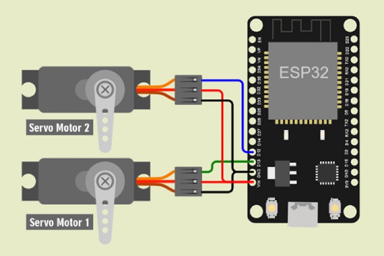
This is a very simple and small circuit with few components. We have to connect the VCC pin of both servo motors to the VIN pin and the GND pin of both servo motors to the GND pin of NodeMCU ESP32, then connect the PWM pin of both the servo to D13 and D12 respectively. The below tables will help you make the connections easily
Note: Never supply this system with more than 6V, it will damage the Servo Motors.
|
1st Servo Motor (SG90) |
NodeMCU ESP32 |
|
VCC (Red Wire) |
VIN |
|
PWM (Yellow Wire) |
D13 |
|
GND (Brown Wire) |
GND |
|
2nd Servo Motor (SG90) |
NodeMCU ESP32 |
|
VCC (Red Wire) |
VIN |
|
PWM (Yellow Wire) |
D12 |
|
GND (Brown Wire) |
GND |
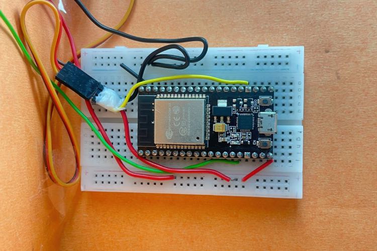
We just used a breadboard and few connecting wires to build the circuit, the garage door model construction was made using simple cardboard boxes and chart papers. In the below image you can see the ESP32 Development board being connected to one servo motor that is pace inside the garage.
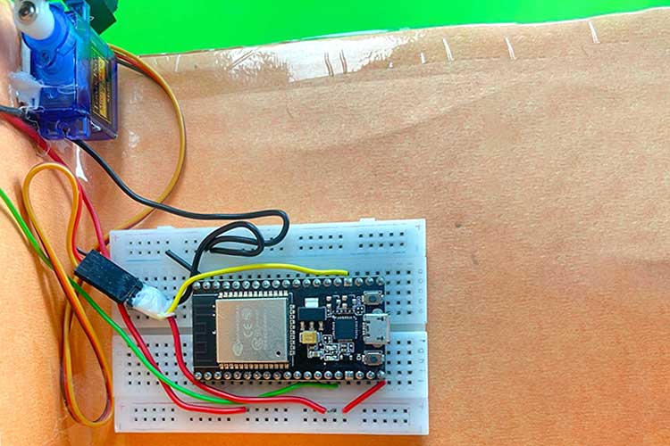
If you want to make the connections more secure you can also solder the ESP32 board on a zero PCB and use male bergstick pins to connect the two servo motors. Also we have powered the entire project using a the USB pot on ESP32 board, if you want to make your project remote you can also consider using a 9V battery or Lithium Battery. Once the connections are ready, we can start programming the ESP32 board to build our Smart Door garage using IoT.
How to Program for IoT Based Smart Garage Door
To program for our IoT Based Smart Garage Door we have to focus on two things, one is to control the servo's from the ESP32 and the other is to build a Smart Garage Door Webserver whcih can be used to open or close our our smart door using a mobile phone. The complete code can be found at the bottom of the page, the explanation for the same is as follows.
#include <ESP32Servo.h>
#include <WiFi.h>
These lines include the necessary libraries for your Arduino sketch. ESP32Servo.h is used to control servo motors with NodeMCU ESP32 Microcontroller and WiFi.h is a library for enabling the wifi feature in the device.
Servo servo1;
Servo servo2;
const char* ssid = "xyz"; // Your Wi-Fi network name
const char* password = "xxxxxxxx"; // Your Wi-Fi password
int pos = 0;
WiFiServer server(80); // Set up the web server on port 80
String header; // Stores the HTTP request
String doorstate = "off"; // Represents the current state of the door
Here we made some variables for servo control and some constants for wifi credentials. Make sure to change the WiFi name and password to yours. The server port and variable to store HTTP requests are declared.
void setup() {
  servo1.attach(15); // Attach servo to GPIO pin 15
  servo2.attach(13); // Attach servo to GPIO pin 13
  Serial.begin(115200); // Begin serial communication for debugging
  WiFi.begin(ssid, password);
  while (WiFi.status() != WL_CONNECTED) {
  delay(500);
  }
  Serial.println(""); // Empty line for spacing
  Serial.println("WiFi connected."); // Print connection status
  server.begin(); // Begin the server
  Serial.println("IP address: ");2
  Serial.println(WiFi.localIP()); // Display the local IP address
}
In the setup part, we have assigned the pins for servo motors and started establishing WiFi connections. It will print the status of Wi-Fi connections and the local IP address on the serial monitor. Note the IP address somewhere it is the address for the web page.
void loop() {
  WiFiClient client = server.available(); // Check for incoming clients
  if (client) {
  String currentLine = "";
  while (client.connected()) {
  if (client.available()) {
  char c = client.read(); // Read incoming data from the client
  header += c; // Store the incoming data
  if (c == '\n') {
  if (currentLine.length() == 0) {
  client.println("HTTP/1.1 200 OK");
  client.println("Content-type:text/html");
  client.println("Connection: close");
  client.println();
  if (header.indexOf("GET /door/on") >= 0) {
  doorstate = "on";
  while (pos < 100) {
  servo1.write(pos);
  servo2.write(180 - pos);
  pos++;
  delay(10);
  }
  } else if (header.indexOf("GET /door/off") >= 0) {
  doorstate = "off";
  while (pos > 0) {
  servo1.write(pos);
  servo2.write(180 - pos);
  pos--;
  delay(10);
  }
  }
In The starting the loop our device is always in command receiving mode from the IOT web server and checks if there is any incoming data if yes then it starts fetching the data from the local IP address and stores it in a variable. Further, it is used to command the servo movement.
After receiving the command here we have to take care of a thing that we have two servo motors that must rotate simultaneously at a different angle because they both are in opposite directions. otherwise, the whole system will collapse. To get out of this problem we have to make a while loop so that both the motors will move 1 degree at a time one by one up to the desired position.
  client.println("<!DOCTYPE html><html>");
  client.println("<head><meta name=\"viewport\" content=\"width=device-width, initial-scale=1\">");
  client.println("<link rel=\"icon\" href=\"data:,\">");
  client.println("<style>html { font-family: Times New Roman; display: inline-block; margin: 0px auto; text-align: center;}");
  client.println(".button { background-color: #195B6A; border: none; border-radius: 50%; color: white; padding: 16px 40px;");
  client.println("text-decoration: none; font-size: 30px; margin: 2px; cursor: pointer;}");
  client.println(".button2 {background-color: #77878A;}</style></head>");
  client.println("<body><h1>IoT Based Garage Door</h1>");
  if (doorstate == "off") {
  client.println("<p><a href=\"/door/on\"><button class=\"button\">Open</button></a></p>");
  } else {
  client.println("<p><a href=\"/door/off\"><button class=\"button button2\">Close</button></a></p>");
  }
  client.println("</body></html>");
  client.println();
  break;
  } else {
  currentLine = ""; // Clear the current line
  }
  } else if (c != '\r') {
  currentLine += c; // Add non-newline characters to the current line
  }
  }
  }
   header = ""; // Clear the header variable
   client.stop(); // Close the connection with the client
  }
}
The next part of this loop is completely devoted to the web interface based on HTML. We have designed the buttons and names you can change them according to your choice. It will create an interactive interface on the webpage so we don’t need to type on and off each time we will have a button for it.
Smart Garage Door IoT Project using ESP32 - Working
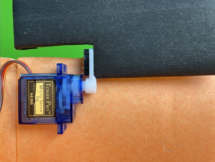
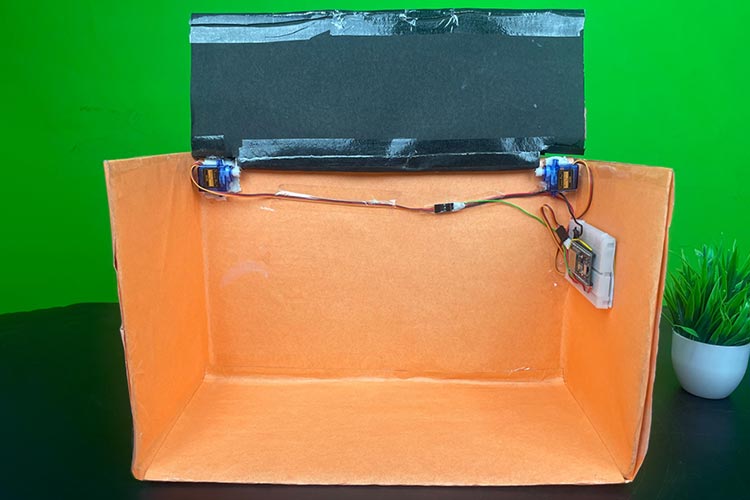
After building the electronics part we have to make a garage for it. I have used cardboard and some chart papers with different colors. Then I mounted the servo motors in the garage doors using a hot glue gun.
After mounting the servo Motors we have to take care of the whole BreadBoard circuit setup. I used double-sided tape to fix it on a side wall and some transparent tape to fix wires.
After completing all the setup and wiring it is ready to work. I am using a Power Bank to power it.
After building the project there is a small process to control it with your smartphone. First of all, If you want to connect this device to your router then make sure to connect your Smartphone with the same network. You can also use your smartphone hotspot to connect your device. As the device gets connected to the internet you can find its IP address on the serial monitor. Then write this IP address at the search bar of any browser on your smartphone and then you will see the Web page. You can add this web page to the Home screen so that you do not need to search IP address every time. Finally, your device is connected to your smartphone and our Smart Garage Door IoT Project is ready for demonstration. The complete working of this project can be found in the video below, hope you learned something useful and enjoyed building this project.
//Code for IoT Smart Garage Door Opener
//by iotdesignpro.com
#include <ESP32Servo.h>
#include <WiFi.h>
Servo servo1;
Servo servo2;
const char* ssid = "0000";
const char* password = "12345678";
int pos = 0;
WiFiServer server(80); // Set port to 80
String header; // Stores the HTTP request
String doorstate = "off"; // state of door
void setup() {
servo1.attach(15);
servo2.attach(13);
Serial.begin(115200);
// Set the pinmode of the pins to which the LEDs are connected and turn them low to prevent flunctuations
//connect to access point
WiFi.begin(ssid, password);
Serial.print("Connecting to ");
Serial.println(ssid);
while (WiFi.status() != WL_CONNECTED) {
delay(500);
Serial.print(".");
}
// Print local IP address and start web server
Serial.println("");
Serial.println("WiFi connected.");
server.begin();
Serial.println("IP address: ");
Serial.println(WiFi.localIP()); // this will display the Ip address of the Pi which should be entered into your browser
}
void loop() {
WiFiClient client = server.available(); // Listen for incoming clients
if (client) { // If a new client connects,
String currentLine = ""; // make a String to hold incoming data from the client
while (client.connected()) { // loop while the client's connected
if (client.available()) { // if there's bytes to read from the client,
char c = client.read(); // read a byte, then
Serial.write(c); // print it out the serial monitor
header += c;
if (c == '\n') { // if the byte is a newline character
// if the current line is blank, you got two newline characters in a row.
// that's the end of the client HTTP request, so send a response:
if (currentLine.length() == 0) {
client.println("HTTP/1.1 200 OK");
client.println("Content-type:text/html");
client.println("Connection: close");
client.println();
if (header.indexOf("GET /door/on") >= 0) {
Serial.println("Door Open");
doorstate = "on";
while (pos < 100) {
Serial.println(pos);
servo1.write(pos);
servo2.write(180 - pos);
pos++;
delay(10);
}
} else if (header.indexOf("GET /door/off") >= 0) {
Serial.println("Door Close");
doorstate = "off";
while (pos > 0) {
servo1.write(pos);
servo2.write(180 - pos);
Serial.println(pos);
pos--;
delay(10);
}
}
// Display the HTML web page
client.println("<!DOCTYPE html><html>");
client.println("<head><meta name=\"viewport\" content=\"width=device-width, initial-scale=1\">");
client.println("<link rel=\"icon\" href=\"data:,\">");
// CSS to style the on/off buttons
client.println("<style>html { font-family: Times New Roman; display: inline-block; margin: 0px auto; text-align: center;}");
client.println(".button { background-color: #195B6A; border: none; border-radius: 50%; color: white; padding: 16px 40px;");
client.println("text-decoration: none; font-size: 30px; margin: 2px; cursor: pointer;}");
client.println(".button2 {background-color: #77878A;}</style></head>");
client.println("<body><h1>IoT Based Garage Door</h1>");
if (doorstate == "off") {
client.println("<p><a href=\"/door/on\"><button class=\"button\">Open</button></a></p>");
} else {
client.println("<p><a href=\"/door/off\"><button class=\"button button2\">Close</button></a></p>");
}
client.println("</body></html>


 Platform")


