


As the water level is decreasing day by day, effective water management has become a necessity. There are many methods for calculating water flow, as well as various types of water flow meters used to measure the amount of water flow in pipelines, but they are all too expensive. Instead of these expensive water flow meters, we can use readily-available and low-cost YFS201 Water Flow Sensor. Apart from measuring water flow, this sensor can be used in Soft Drinks Industries and Chemical industries to continually measure and quantify the liquids that they are handling during this automation process.
So in today’s tutorial, we are going to build an IoT based water flow meter using the YFS201 water flow sensor and NodeMCU. It will calculate the flow rate and quantity of water and send it to the cloud (Thinger.IO) to monitor the consumption of water.
Components Required
- NodeMCU ESP8266
- Water Flow Sensor
- Jumper Wires
Circuit Diagram
The circuit diagram for the IoT Water Flow Meter is given below. It is straightforward as we are only interfacing NodeMCU and Water Flow Sensor.
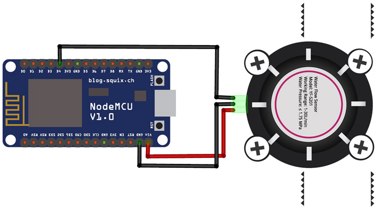
The VCC (Red Wire) and GND (Black Wire) pins of flow sensors are connected to 5V and GND pins of NodeMCU while the Signal pin (Yellow Wire) is connected to D4 pin of NodeMCU.
YFS201 Water Flow Sensor
Water Flow Sensor, as the name suggests, is a device to measure the flow of water. The water flow sensor works on the principle of the Hall Effect. According to Hall Effect principle, when a conductor or semiconductor with current flowing in one direction is introduced perpendicular to a magnetic field, a voltage could be measured at right angles to the current path.
In the water flow sensor, a rotor is placed in the path of liquid to utilize the Hall Effect. The shaft of the rotor is connected to the Hall Effect sensor. When the liquid flows through the water flow sensor, it rotates the rotor. As it is an arrangement of a current flowing coil and a magnet connected to the shaft of the rotor, a voltage/pulse is generated. The number of pulses per second or minute is used to measure the flow rate and total amount of water passed through the sensor.
The water flow sensor has three wires, i.e. Red, Yellow, and Black. The Red wire is used for supply voltage ranging from 5V to 18V, and the Black wire is GND. The Yellow wire is an output pin through which we can read the sensor data.
Thinger.io Setup
Thinger.io is an Open-Source Platform for the Internet of Things. It provides every needed tool to prototype, scale, and manage connected products in a very simple way. Thinger.io provides three essential tools, i.e. Data Bucks, Dashboard, and Endpoint, to work with devices data; these tools can be used to visualize the device data, extend the interoperability of the devices.
To send data to Thinger.io, you first need to add a new device on Thinger.IO and get the device credentials. These credentials will be used in the code to set-up a connection between NodeMCU and Thinger.IO cloud to send data to the cloud.
So sign in to your Thinger.io account and follow the below steps to connect your device.
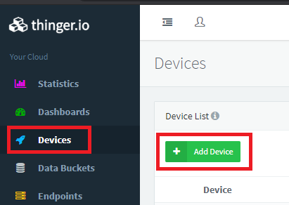
Step 1: The first step is to create a new device. To create a new device, click on Devices in the menu tab and then click on the Add Device button.
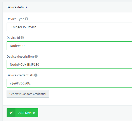
Then fill the form with the device ID, description, and Credentials or generate random credentials for your device and click on ‘Add Device.’
That’s all; your device is ready to connect. In the next step, we will program the NodeMCU to send the data to the Thinger.io platform.
Programming NodeMCU
The complete code for sending data to Thinger.io is given at the end of the page. Here we are explaining some important parts.
Start the code by including all the required libraries. The ThingerESP8266.h library is used to establish a connection between the IoT platform and the NodeMCU. You can install the ThingerESP8266.h library from the Arduino IDEs library manager.
#include <ThingerESP8266.h>
#include <ESP8266WiFi.h>
Next, you need to enter your credentials in your code, so the device can be recognized and associated with your account.
#define USERNAME "choudharyas"
#define DEVICE_ID "NodeMCU"
#define DEVICE_CREDENTIAL "FcLySVkP8YFR"
After that, define the pin where you connected the Water Flow Sensor.
#define SENSOR D4
After that, we need to define some variables to hold the values. The volatile byte “count” will store the number of pulses.
volatile byte pulseCount;
byte pulse1Sec = 0;
float flowRate;
unsigned int flowMilliLitres;
unsigned long totalMilliLitres;
Now create a new function to increase the pulse count whenever a pulse is received. The interrupt function will be calling the pulseCounter() function.
void IRAM_ATTR pulseCounter()
{
  pulseCount++;
}
Inside the void setup(), define the water flow sensor pin as input pull-up. NodeMCU has built-in pull-up resistors that can be accessed by setting the pinMode() as INPUT_PULLUP. Also, set the pulse count and flow rate to zero.
pinMode(SENSOR, INPUT_PULLUP);
pulseCount = 0;
flowRate = 0.0;
flowMilliLitres = 0;
totalMilliLitres = 0;
previousMillis = 0;
Now in the next lines, define the interrupt. In the attachInterrupt() function, it is specified that ‘SENSOR’ is the external interrupt pin, and ‘pulseCounter’ function is called whenever a pulse is received.
attachInterrupt(digitalPinToInterrupt(SENSOR), pulseCounter, FALLING);
Now inside the void loop(), calculate the flow rate and the total amount of water using the pulse count and millis.
currentMillis = millis();
  if (currentMillis - previousMillis > interval) {
    pulse1Sec = pulseCount;
    pulseCount = 0;
    flowRate = ((1000.0 / (millis() - previousMillis)) * pulse1Sec) / calibrationFactor;
    previousMillis = millis();
    flowMilliLitres = (flowRate / 60) * 1000;
    totalMilliLitres += flowMilliLitres;
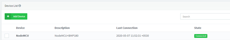
Now connect the Water Flow sensor to NodeMCU and upload the code. The NodeMCU will use your account credentials to connect with the device that you created earlier. If it connects successfully, it will show connected, as shown in the below image:
You can check your device statistics like Transmitted Data, Received Data, IP Address, Time Connected, etc. by just clicking on the device name from Devices menu.
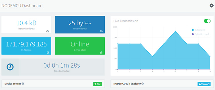
As we are now receiving the data, we will create a dashboard to visualize the data using the widgets.
To create a Dashboard, click on Dashboards from the menu tab and then click on ‘Add Dashboard.’
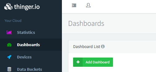
Now in the next window, enter the dashboard details like dashboard name, ID, and Description and then click on Dashboard.
After this, access the new dashboard by clicking on the Dashboard name. By default, the dashboard will appear empty. To add the Widgets, you first need to enable the edit mode by clicking on the upper-right switch of the dashboard. Then click on the ‘’Add Widget’ button.

When you click on the ‘Add Widget’ button, it will show a popup where you can select the widget type, background color, etc. In my case, I have selected the Gauge Widget.
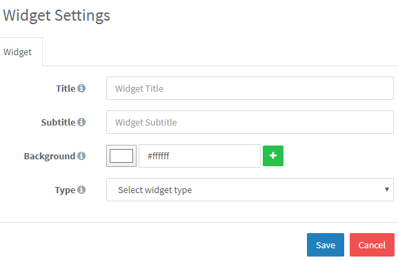
When you click on save, it will take you to the next screen where you need to select the Source Value, Device, Resource, Value, and Refresh mode. Select all the values and then click on the Save button.
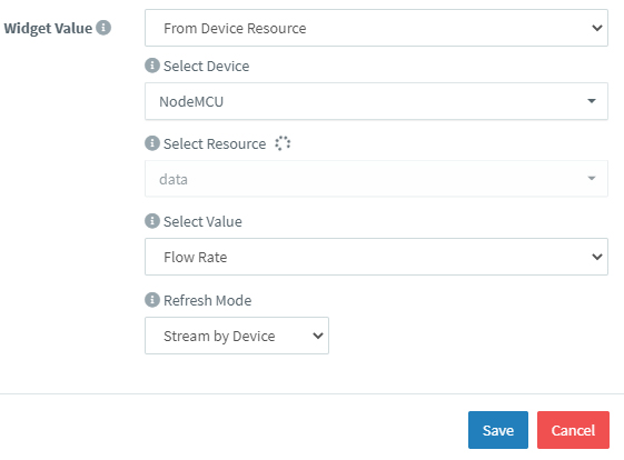
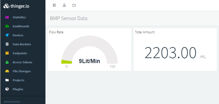
Now repeat the same procedure for the other variable. My dashboard looked like this:
A complete working video and code are given below.
#include <ThingerESP8266.h>
#include <ESP8266WiFi.h>
#define USERNAME "Your Account Username"
#define DEVICE_ID "Device-ID"
#define DEVICE_CREDENTIAL "Your Private Key"
#define SSID "Wi-Fi Name"
#define SSID_PASSWORD "Password"
#define SENSOR D3
ThingerESP8266 thing(USERNAME, DEVICE_ID, DEVICE_CREDENTIAL);
long currentMillis = 0;
long previousMillis = 0;
int interval = 1000;
//boolean ledState = LOW;
float calibrationFactor = 4.5;
volatile byte pulseCount;
byte pulse1Sec = 0;
float flowRate;
unsigned int flowMilliLitres;
unsigned long totalMilliLitres;
void IRAM_ATTR pulseCounter()
{
pulseCount++;
}
void setup()
{
Serial.begin(115200);
thing.add_wifi(SSID, SSID_PASSWORD);
pinMode(SENSOR, INPUT_PULLUP);
pulseCount = 0;
flowRate = 0.0;
flowMilliLitres = 0;
totalMilliLitres = 0;
previousMillis = 0;
attachInterrupt(digitalPinToInterrupt(SENSOR), pulseCounter, FALLING);
}
void loop()
{
currentMillis = millis();
if (currentMillis - previousMillis > interval) {
pulse1Sec = pulseCount;
pulseCount = 0;
flowRate = ((1000.0 / (millis() - previousMillis)) * pulse1Sec) / calibrationFactor;
previousMillis = millis();
flowMilliLitres = (flowRate / 60) * 1000;
totalMilliLitres += flowMilliLitres;
// Print the flow rate for this second in litres / minute
Serial.print("Flow rate: ");
Serial.print(int(flowRate)); // Print the integer part of the variable
Serial.print("L/min");
Serial.print("\t"); // Print tab space
// Print the cumulative total of litres flowed since starting
Serial.print("Output Liquid Quantity: ");
Serial.print(totalMilliLitres);
Serial.print("mL / ");
Serial.print(totalMilliLitres / 1000);
Serial.println("L");
thing["data"] >> [](pson& out){
out["Flow Rate"] = flowRate;
out["Total"]= totalMilliLitres;
};
thing.handle();
thing.stream(thing["data"]);
}
}


