


You all will agree with the fact that high energy consumption by our household appliances is quite bothering and each month we make every possible effort to reduce the electricity bill. Not just that, in the quest to understand and monitor the power usages, we keep checking electricity meters installed in our home/offices. What if we can monitor the electricity bill from anywhere on our smartphones? Yes, with the help from the Internet of Things, we can easily monitor power consumption using a smart energy meter. We have previously done other IoT based Remote Monitoring projects like Temperature and Humidity Monitoring, Battery Monitoring, Food Monitoring, Air Quality Monitoring, etc.
For quite some time, I have been trying to find out ways to build a simple yet accurate way to measure and monitor the power usages from anywhere, be it at home office or on the go. After some research, I decided to build a simple one by using a current sensor with NodeMCU and send the measured current values to the IoT Cloud Platform. This can be done with the help of the Adafruit MQTT IoT Platform which is free and doesn’t require a subscription. To build this energy meter, you will only need very few components and an internet connection.
MATERIAL REQUIRED
- ACS712 Current Sensor
- NODE MCU ESP8266 Module
- Mobile charger and USB cable (for power supply and program uploading & for serial monitor reading)
- Bulb holder
- Stable load - here 100 watts bulb
- Some wires
Different Methods for Current Sensing
There are many ways to measure the current flowing through a wire, the popular current sensing methods are discussed here. The current sensing is done in two ways, namely the Direct sensing method and the indirect sensing method. Direct sensing method uses Ohm’s law to measure the voltage drop occurring in a wire when current flows through it, but ACS712 uses indirect current sensing method (which is measured by calculating magnetic field by applying either Faraday’s Law or Ampere’s Law), hence there will be no external load on the current-carrying wire and no direct contact is needed. It is similar to how clamp meter works. We will discuss more on ACS712 working later in this article.
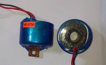
Another popular method for Current sensing is using a Current Transformer (CT). It is also an indirect current sensing method. It also works in the same way where the carrying wire passes through the center hole of CT transformer and the CT transformer consists of a coil that will pick up the magnetic flux generated by the current-carrying wire. By measuring the voltage induced in this coil, we can calculate the current that passed through the wire. A typical current transformer is shown below.
ACS712 Current Sensor
ACS712 is based on the theory of Hall effect which was discovered by Dr. Edwin Hall in 1879. According to the principle, when a current-carrying conductor is placed in the magnetic field, a voltage is generated across its edges perpendicular to the direction of both current and the magnetic field. This voltage is known as hall voltage and its typical value is in the order of few millivolts. So by measuring the Hall voltage, we will be able to calculate the amount of current flowing through the sensor. A typically ACS712 Current sensor is shown below.
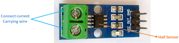
When an electron flows through a wire or path, it creates a magnetic field in its surroundings. This magnetic field is sensed by the Hall effect IC and a voltage output is produced which can be directly fed into the microcontroller or ESP board. This sensor is located at the surface of the IC on a bold copper conducting path from phase input-output.
ACS712 sensor has 4 variants (185mV=5A module,100mV=10A & 66mV for 20A & 30A module) and each variant is rated is for a different current value. You can choose any of them as per your requirement but for better calibration, millivolts per Amp value should be correctly assigned to the coding. Note that as the current rating of the sensor increases, the accuracy will decrease.
Circuit Diagram for NodeMCU Energy Meter
The complete circuit diagram for IoT based Energy Meter is shown below. Although it is very simple, you should follow the graphical representation for a better understanding and make sure the connections are correct. Be advised that working with mains requires practice and hence do not build this circuit if you are not sure how to do it.
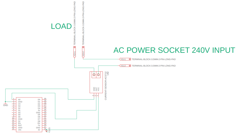
We have used NodeMCU with ACS712 Current Sensor, the current sensor will measure the current consumed by our AC load and the NodeMCU will measure this current, calculate the power (assuming the voltage is constant) and send the power value to a cloud platform like Adafruit IO. A visual info-graphic circuit diagram is also given below for your convenience.
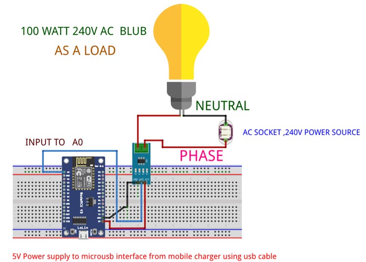
As you can see the NodeMCU will be powered through the USB port using a 5V mobile charger and the AC load will be connected to the 220V AC mains through our ACS712 current sensor.
The sensor has a maximum input voltage on VCC is 5V but it also works fine in lower voltage. Please note that the ASC712 output offset voltage is dependable on its operating voltage (generally half of the operating voltage). Since we powered up the module from the ESP 3V output pin the ACS712 module output offset voltage is 1.5 volt (1500 mv) when there is no current flowing. ESP has an onboard voltage divider circuit internally, so we are giving direct input from ACS712 output to the A0 input pin.
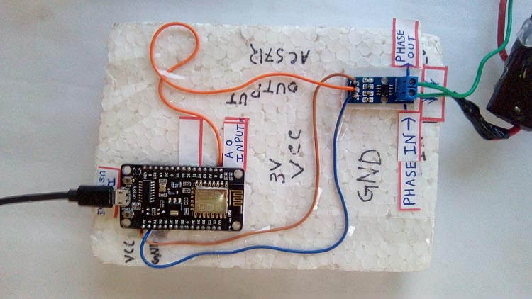
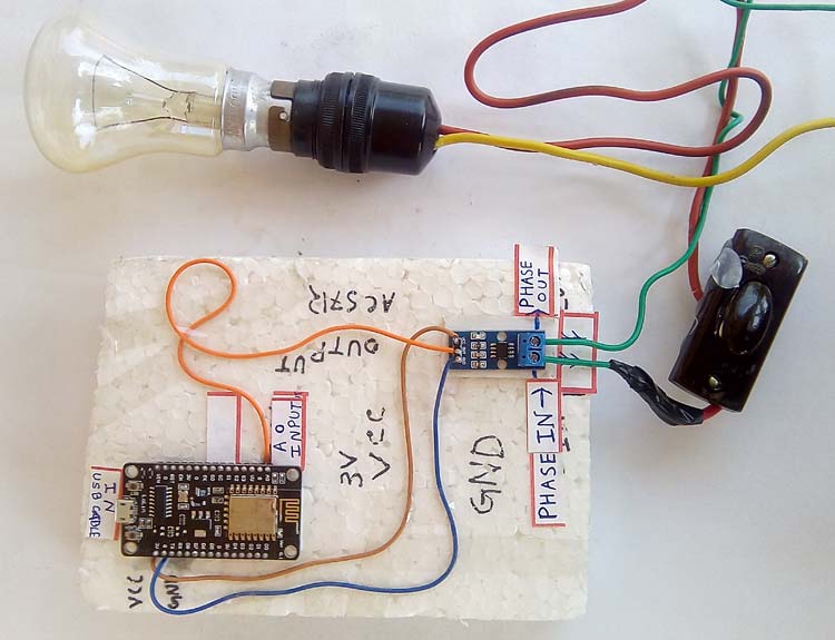
Make the connections as shown in the circuit above. I directly soldered the wire between the NodeMCU and ACS712 sensor but you can also use a breadboard and connecting wires. My setup looks like this below when ready.
Adafruit IO for Energy Monitoring
When everything is done, it’s time to open Account on the “Adafruit IO” IoT platform and connect our circuit with the Adafruit server to monitor energy meter readings live. Follow the below step by step procedure for it:
1. For Adafruit IO setup, the first thing you will need to do is to sign up to Adafruit IO. To sign up, go to Adafruit IO’s site https://io.adafruit.com and click on ‘Get started for Free’ on the top right of the screen.

2. After this, a window will pop up where you need to fill your details.

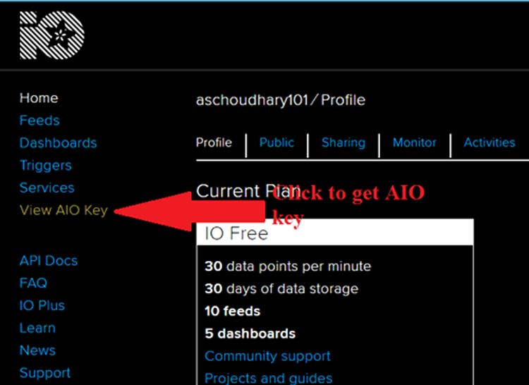
In sign up window, fill your details like your name, mail id, username, etc. Then click on save settings and your account is created. To get your AIO key, click on ‘View AIO Key’.
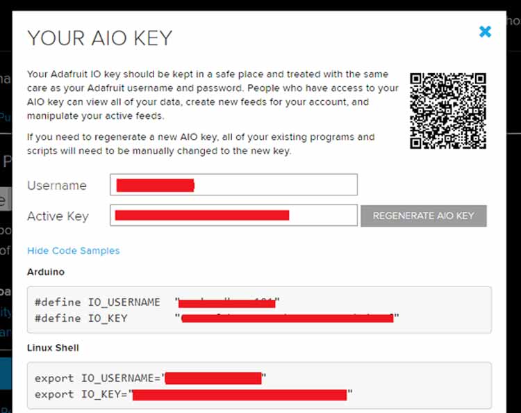
3. A window will pop up with your Adafruit IO AIO Key. Copy this key you'll need it later in your python code.
4. Now after this, you need to create a feed. To create a feed, click on ‘Feed’. Then click on ‘Actions’, you will see some options from them click on ‘Create a New Feed’.

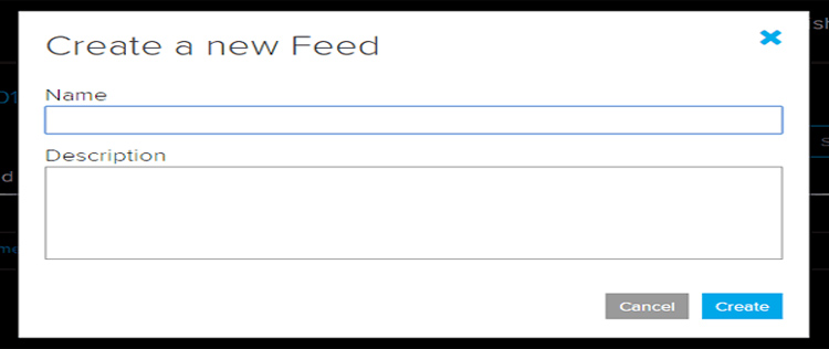
5. After this a new window will open where you need to input:
Name – In name option, write a short descriptive name of your feed. You can use letters, numbers, and spaces.
Description - A long-form description of your data. This field is not required, but you can write a description of your data.
6. Click on ‘Create’, you will then be redirected to your new feed.
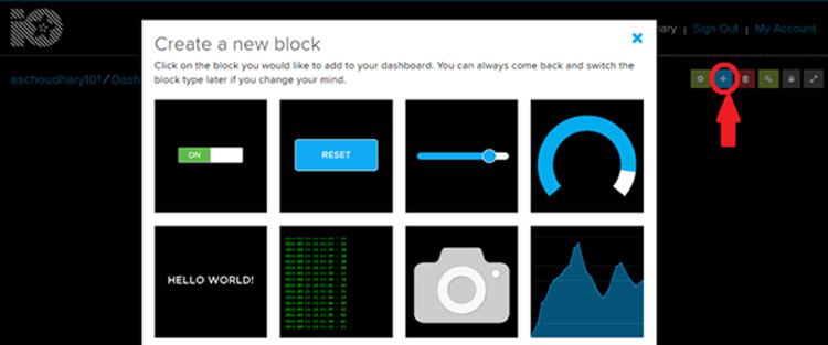
7. Next, to add a new Toggle Block, you need to create a dashboard. Creating a Dashboard is the same as Feed. So follow the same steps. Now to add a block, click on ‘Plus sign’ on the top right corner of the screen and click on the first option.
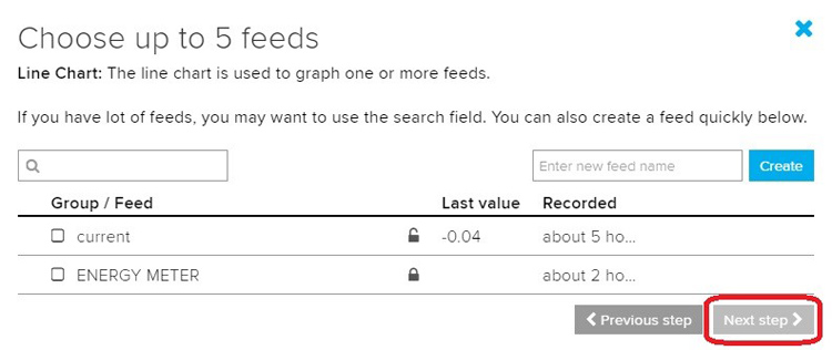
8. Now, select your feeds which we created previously and click on “Next step”.
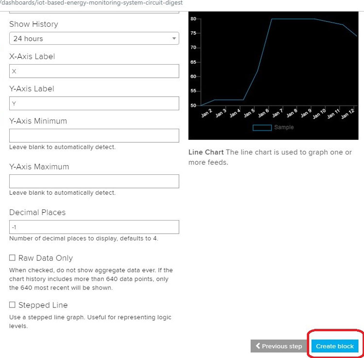
9. Change the settings of the block if you want or keep it as it is and click on “Create Block”.
NodeMCU Program for IoT Energy Meter
Complete Code for IoT Energy Meter can be found at the end of this article but we need to download some library for this code. You can download it through the library manager or can download it from the below link and add using the “import library” option on Arduino IDE.
First, we will include all the library for ESP8266 and Adafruit MQTT.
#include <ESP8266WiFi.h>
#include "Adafruit_MQTT.h"
#include "Adafruit_MQTT_Client.h"
Thereafter, we define the SSID & PASSWORD of your wifi network.
#define WLAN_SSID       "...your WiFi… SSID..."
#define WLAN_PASS       "...your…WiFi…password..."
This part of the coding defines the “Adafruit server” which is the link of the website itself along with Adafruit server “port”, your account “username” and your “AIO KEY”.
#define AIO_SERVER      "io.adafruit.com"
#define AIO_SERVERPORT  1883                   // use 8883 for SSL
#define AIO_USERNAME    "...your Adafruit Account username..."
#define AIO_KEY         "...your authentication AIO key..."
Then we have a variable millivolt per Ampere sensitivity which has to be mentioned in the coding, this is different for all the variants of ACS712 sensor (185mV for 5Amp module, 100mV for 10A, 66mv for 20 & 30 Amp module).
int mVperAmp = 66;
Under the VOID SETUP, we are just connecting to the wifi.
void setup()
{
 Serial.begin(9600);
 WiFi.begin(WLAN_SSID, WLAN_PASS);
while (WiFi.status() != WL_CONNECTED)
{
Serial.println("connecting....");
delay(1000);
  }
  Serial.println("Connected");
}
In the loop function, first, we connect with the MQTT and get the voltage value from the sensor.
void loop()
 {
        MQTT_connect();
        Voltage = getVPP();
Inside this function, we are taking value for 1 second, in that 1 second, we are going to read the value from the sensor, then we are going to calculate the maximum value and the minimum value. So, it’s basically in that 1 second that we are going to store what is the minimum value of the voltage and what is the maximum value of the voltage and the result is difference between the maximum value of the voltage and minimum value of the voltage and multiplied by 5 and divided by 1024 all is used for converting to current and it is related to calibration factor.
{
  float result;
  int readValue; //value read from the sensor
  int maxValue = 0; // store max value here
  int minValue = 1024; // store min value here
  uint32_t start_time = millis();
  while ((millis() - start_time) < 1000) //sample for 1 Sec
  {
  readValue = analogRead(sensorIn);
 // see if you have a new maxValue
 if (readValue > maxValue)
{
/*record the maximum sensor value*/
maxValue = readValue;
 }
  if (readValue < minValue)
 {
  /*record the menimum sensor value*/
minValue = readValue;
    }
  }
// Subtract min from max
  result = ((maxValue - minValue) * 5) / 1024.0;
  return result;
}
If you go through the handmade diagram, I have prepared for you all, you can see that there are two lines, the top line which is the name I have given (Vp) indicates the maximum value of the voltage and bottom is (–Vp) which indicates the minimum value of the voltage. If you take the difference between those two lines, you will get the (Vpp) voltage peak to -peak value.
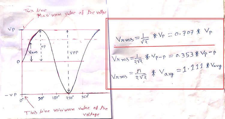
Then we return to the main function. Under the loop, you can see we are going to convert peak voltage to RMS value using the formulae explained above. Note that we have divided the measured voltage by 2 to get the value of either the positive or negative side.
RMS Voltage = Peak Voltage x 0.707
After that, we convert the voltage to current, for that we are dividing the Vrms value by the millivolt per amp value of the current sensor (I’m using 30 Amp module so it is 66 mVperamp) and multiply by 1000 so that we get it into the Amp not in milli Amps.
Vrms = (Voltage / 2.0) * 0.707; // sq root
  Irms = ((Vrms * 1000) / mVperAmp) ;
  Serial.print(Irms);
  Serial.println(" Amps");
Then we will be printing this current value on the serial monitor of Arduino IDE as well as on the MQTT IoT Platform.
Serial.print(Irms);
 Serial.println(" Amps");
if (! photocell.publish(Irms))
  {
    Serial.println("Failed");
  }
  else
  {
    Serial.println("OK!");
  }
  delay(2000);
}
Working of NodeMCU based IoT Energy Meter
In this way, you can build your IoT-based energy meter that can be monitored from anywhere in the world. Once you have made the connection and uploaded the code, you should see the power reading on the AdafruitIO console.
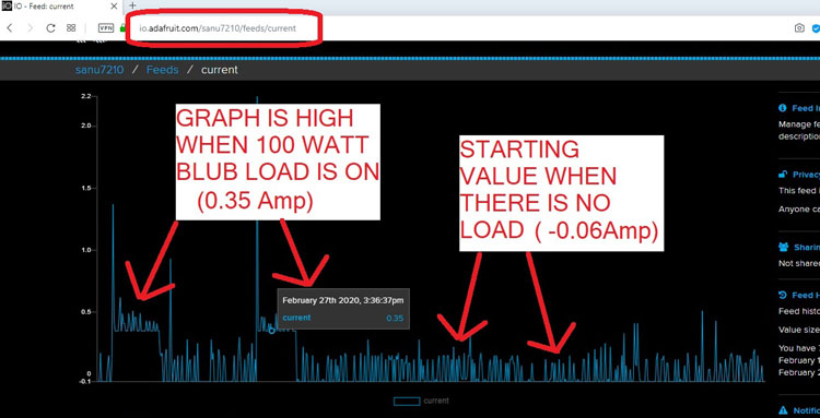
We have tested it on different load conditions like with a 100-watt bulb, with 200-watt Blub, and with 500 watts halogen, etc. Here is the screenshot with zero to 100-watt load conditions on the MQTT IoT platform.
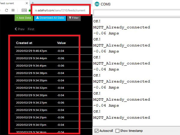
Along with the graph, the value is also printed on MQTT and it is compared with the serial monitor as shown below.
Complete working can also be found in the video linked below. I hope you understood the tutorial and built something useful. If you have any questions, feel free to leave them in the comment section below.
#include <ESP8266WiFi.h>
#include "Adafruit_MQTT.h"
#include "Adafruit_MQTT_Client.h"
#define WLAN_SSID "SS_NETWORK"
#define WLAN_PASS "nilanjan9563136731"
#define AIO_SERVER "io.adafruit.com"
#define AIO_SERVERPORT 1883 //use 8883 for SSL
#define AIO_USERNAME "sanu7210"
#define AIO_KEY "aio_qpkA72BNygAqkunkqKKvX1EoJSjw"
// Create an ESP8266 WiFiClient class to connect to the MQTT server.
WiFiClient client;
// or... use WiFiFlientSecure for SSL
//WiFiClientSecure client;
// Setup the MQTT client class by passing in the WiFi client and MQTT server and login details.
Adafruit_MQTT_Client mqtt(&client, AIO_SERVER, AIO_SERVERPORT, AIO_USERNAME, AIO_KEY);
Adafruit_MQTT_Publish photocell = Adafruit_MQTT_Publish(&mqtt, AIO_USERNAME "/feeds/current");
const int sensorIn = A0;
int mVperAmp = 66; //185mV for 5Amp module , 100mV for 10A , 66mv for 20 & 30 Amp module
double Voltage = 0;
double Vp = 0;
double Vrms = 0;
double Irms = 0;
// Bug workaround for Arduino 1.6.6, it seems to need a function declaration
// for some reason (only affects ESP8266, likely an arduino-builder bug).
void MQTT_connect();
void setup() {
Serial.begin(9600);
WiFi.begin(WLAN_SSID, WLAN_PASS);
while (WiFi.status() != WL_CONNECTED)
{
Serial.println("connecting....");
delay(1000);
}
Serial.println("Connected");
}
void loop() {
MQTT_connect();
Voltage = getVPP();
Vrms = (Voltage / 2.0) * 0.707; // sq root
Irms = ((Vrms * 1000) / mVperAmp) ;
Serial.print(Irms);
Serial.println(" Amps");
if (! photocell.publish(Irms))
{
Serial.println("Failed");
}
else
{
Serial.println("OK!");
}
delay(2000);
}
double getVPP()
{
float result;
int readValue; //value read from the sensor
int maxValue = 0; // store max value here
int minValue = 1024; // store min value here
uint32_t start_time = millis();
while ((millis() - start_time) < 1000) //sample for 1 Sec
{
readValue = analogRead(sensorIn);
// see if you have a new maxValue
if (readValue > maxValue)
{
/*record the menimum sensor value*/
maxValue = readValue;
}
if (readValue < minValue)
{
/*record the menimum sensor value*/
minValue = readValue;
}
}
// Subtract min from max
result = ((maxValue - minValue) * 5) / 1024.0;
return result;
}
void MQTT_connect() {
int8_t ret;
// Stop if already connected.
if (mqtt.connected()) {
Serial.println("MQTT_Already_connected");
return;
}
Serial.print("Connecting to MQTT... ");
uint8_t retries = 3;
while ((ret = mqtt.connect()) != 0) { // connect will return 0 for connected
Serial.println(mqtt.connectErrorString(ret));
Serial.println("Retrying MQTT connection in 5 seconds...");
mqtt.disconnect();
delay(5000); // wait 5 seconds
retries--;
if (retries == 0) {
// basically die and wait for WDT to reset me
while (1);
}
}
Serial.println("MQTT Connected!");
}


