


We surely can’t imagine a world without sound. Sound is one of an integral part of our day to day life, everything just becomes monotonous without the presence of audio. But too much of anything is dangerous, with the advent of automobiles, loudspeakers, etc. sound pollution has become a threat in recent days. So, in this project, we will build an IoT decibel meter to measure sound in a particular place and record the value in a graph using IoT. A device like this will be useful in places like hospitals and schools to track and monitor the sound levels and take action accordingly. Previously we have also built an Air pollution meter to monitor air quality using IoT.
A sound level meter is employed for acoustic (sound that travels through the air) measurements. The simplest sort of microphone for sound level meters is the capacitor microphone, which mixes precision with stability and reliability. The diaphragm of the microphone responds to changes in air pressure caused by sound waves. That’s why the instrument is usually mentioned as a sound pressure level (SPL) Meter.
Sound level meters are commonly utilized in sound pollution studies for the quantification of various sorts of noise, especially for industrial, environmental, mining, and aircraft noise. The reading from a sound level meter doesn't correlate well to human-perceived loudness, which is best measured by a loudness meter. Specific loudness may be a compressive nonlinearity and varies at certain levels and certain frequencies. These metrics also can be calculated in several other ways.
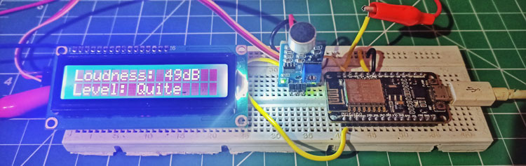
Here we are going to make an IoT based decibel meter that will measure the sound in decibels(dB) using a sound sensor and display it to the LCD display along with that, it will also be pushing the readings to the Blynk IoT platform making it accessible from across the world.
Components Required
- ESP8266 NodeMCU Board
- Microphone sensor
- 16*2 LCD Module
- Breadboard
- Connecting wires
How does Microphone Module Work?
The microphone based sound sensor is used to detect sound. It gives a measurement of how loud a sound is. The sound sensor module is a small board that mixes a microphone (50Hz-10kHz) and a few processing circuitry to convert sound waves into electrical signals. This electrical signal is fed to on-board LM393 High Precision Comparator to digitize it and is made available at the OUT pin.
The module features a built-in potentiometer for sensitivity adjustment of the OUT signal. We will set a threshold by employing a potentiometer. So that when the amplitude of the sound exceeds the edge value, the module will output LOW, otherwise, HIGH. Apart from this, the module has two LEDs. The facility LED will illuminate when the module is powered. The Status LED will illuminate when the digital output goes LOW.
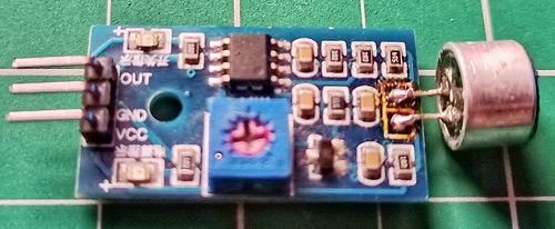
The sound sensor only has three pins: VCC, GND & OUT. VCC pin supplies power for the sensor & works on 3.3V to 5V. OUT pin outputs HIGH when conditions are quiet and goes LOW when sound is detected.
Circuit Diagram for IoT Sound Meter
The connections are pretty simple, we just have to connect the sound sensor to one of the Analog pin and the LCD to the I2C pins.
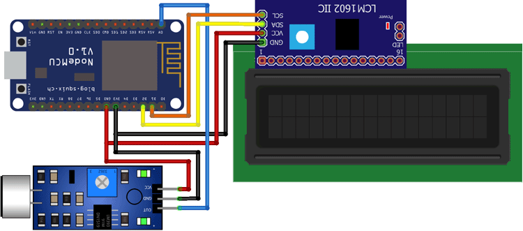
In the above diagram, we have connected the power pins of the sound sensor and LCD display to 3v3 and GND pin of NodeMCU. Along with that, we have also connected the SCL and SDA pins of the module to D1 and D2 respectively, and the OUT pin of the sound sensor to A0 pin.
Setting up Blynk for Remote Monitoring
For the IoT part, we will be using the Blynk IoT platform. We have previously used Blynk with Nodemcu to build many different projects. You can also check out other Blynk projects that we have built earlier. In this application, we will be adding a gauge to display the intensity of sound in decibels. Let us set up the app quickly.
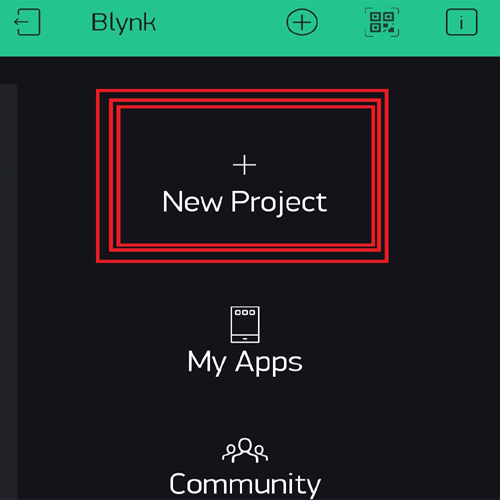
- First of all, install the Blynk app from PlayStore and create an account.
- Click on the create button and create your new project.
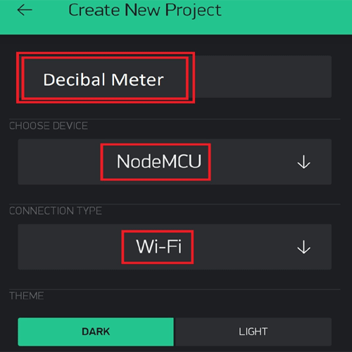
- Give your project a name and choose the board as NodeMCU and connection type as Wi-Fi.
- An auth token will be sent to your registered email id. Keep it safe as it will be used later on while programming.
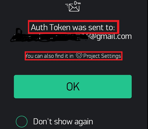
Auth Token is a unique alphanumeric string to identify your project in the Blynk’s server and assigning the correct data through it.
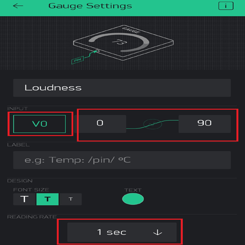
- Now drag and drop a gauge from the list and configure it.
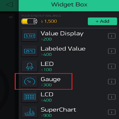
- Connect the gauge to virtual pin V0 and set the values to 0 and 90 respectively, also set the reading rate to 1 sec.
And now you’re done with setting up Blynk. Let us jump to the coding part.
Program for IoT Decibel Meter
Here, we have to develop a code that takes input from the sound sensor and maps it value to decibels and after comparing the loudness, it should not only print it to the 16*2 LCD display but should also send it to the Blynk server.
The complete code for this project can be found at the bottom of this page. You can directly copy-paste it in your IDE and change only three parameters i.e. SSID, pass, and auth token. The explanation of the code is as follows.
In the very first part of the code, we have included all the necessary libraries and definitions. Also, we have defined the necessary variables and objects for further programming.
#define BLYNK_PRINT Serial
#include <ESP8266WiFi.h>
#include <BlynkSimpleEsp8266.h>
#include <LiquidCrystal_I2C.h>
#define SENSOR_PIN A0
LiquidCrystal_I2C lcd(0x3F, 2, 1, 0, 4, 5, 6, 7, 3, POSITIVE);
const int sampleWindow = 50;
unsigned int sample;
int db;
char auth[] = "IEu1xT825VDt6hNfrcFgdJ6InJ1QUfsA";
char ssid[] = "YourSSID";
char pass[] = "YourPass";
Further ahead, we have created a Blynk function to handle the virtual pin that our gauge is connected to. We are simply sending the values stored in the dB variable to the V0 pin.
BLYNK_READ(V0)
{
  Blynk.virtualWrite(V0, db);
}
In the setup part of the code, we are defining the pin mode as input and beginning the LCD display as well as the Blynk function.
void setup() {
  pinMode (SENSOR_PIN, INPUT);
  lcd.begin(16, 2);
  lcd.backlight();
  lcd.clear();
  Blynk.begin(auth, ssid, pass);
}
In the loop part, we are doing all the processing tasks like comparison and value assignment along with running the Blynk function.
void loop() {
Blynk.run();
unsigned long startMillis = millis(); // Start of sample window
float peakToPeak = 0; //peak-to-peak level
unsigned int signalMax = 0; //minimum value
unsigned int signalMin = 1024; //maximum value
// collect data for 50 mS
while (millis() - startMillis < sampleWindow)
{
sample = analogRead(SENSOR_PIN); //get reading from microphone
if (sample < 1024) // toss out spurious readings
{
if (sample > signalMax)
{
signalMax = sample; // save just the max levels
}
else if (sample < signalMin)
{
signalMin = sample; // save just the min levels
}
}
}
peakToPeak = signalMax - signalMin; // max - min = peak-peak amplitude
Serial.println(peakToPeak);
db = map(peakToPeak, 20, 900, 49.5, 90); //calibrate for deciBels
lcd.setCursor(0, 0);
lcd.print("Loudness: ");
lcd.print(db);
lcd.print("dB");
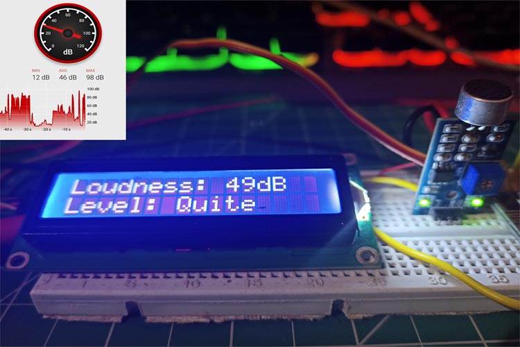
if (db <= 50)
{
lcd.setCursor(0, 1);
lcd.print("Level: Quite");
}
else if (db > 50 && db < 75)
{
lcd.setCursor(0, 1);
lcd.print("Level: Moderate");
}
else if (db >= 75)
{
lcd.setCursor(0, 1);
lcd.print("Level: High");
}
delay(600);
lcd.clear();
}
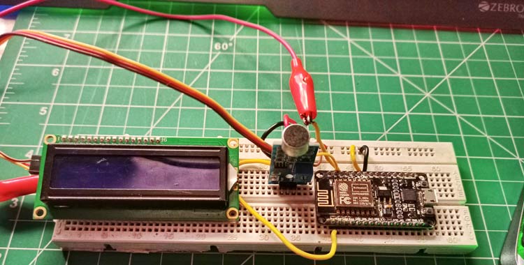
Working of the Project
Now that you have understood the code, you can simply upload it to your NodeMCU board and the project should start working.
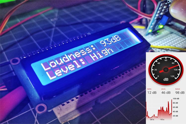
To make sure the values are correct, I compared them to an android application on my phone that could measure sound. As you can see from the pictures, the results were quite close.
The complete working of this project is also demonstrated in the video linked below. Hope you enjoyed the project and learned something useful if you have any questions, leave them in the comment section below.
#define BLYNK_PRINT Serial
#include <ESP8266WiFi.h>
#include <BlynkSimpleEsp8266.h>
#include <LiquidCrystal_I2C.h>
#define SENSOR_PIN A0
LiquidCrystal_I2C lcd(0x3F, 2, 1, 0, 4, 5, 6, 7, 3, POSITIVE);
const int sampleWindow = 50;
unsigned int sample;
int db;
char auth[] = "IEu1xT825VDt6hNfrcFgdJ6InJ1QUfsA";
char ssid[] = "realme 6";
char pass[] = "evil@zeb";
BLYNK_READ(V0)
{
Blynk.virtualWrite(V0, db);
}
void setup() {
pinMode (SENSOR_PIN, INPUT);
lcd.begin(16, 2);
lcd.backlight();
lcd.clear();
Blynk.begin(auth, ssid, pass);
}
void loop() {
Blynk.run();
unsigned long startMillis = millis(); // Start of sample window
float peakToPeak = 0; // peak-to-peak level
unsigned int signalMax = 0; //minimum value
unsigned int signalMin = 1024; //maximum value
// collect data for 50 mS
while (millis() - startMillis < sampleWindow)
{
sample = analogRead(SENSOR_PIN); //get reading from microphone
if (sample < 1024) // toss out spurious readings
{
if (sample > signalMax)
{
signalMax = sample; // save just the max levels
}
else if (sample < signalMin)
{
signalMin = sample; // save just the min levels
}
}
}
peakToPeak = signalMax - signalMin; // max - min = peak-peak amplitude
Serial.println(peakToPeak);
db = map(peakToPeak, 20, 900, 49.5, 90); //calibrate for deciBels
lcd.setCursor(0, 0);
lcd.print("Loudness: ");
lcd.print(db);
lcd.print("dB");
if (db <= 50)
{
lcd.setCursor(0, 1);
lcd.print("Level: Quite");
}
else if (db > 50 && db < 75)
{
lcd.setCursor(0, 1);
lcd.print("Level: Moderate");
}
else if (db >= 75)
{
lcd.setCursor(0, 1);
lcd.print("Level: High");
}
delay(600);
lcd.clear();
}


