


Smart power monitoring is getting increasingly popular to improve energy efficiency in medium/small scale industries, multi-story buildings, etc. We have previously built a smart energy meter which can measure power and report usage online. While this type of system is popularly used in energy meters, another most commonly available technique to measure current is by using a current transformer (CT). CT can detect and measure AC current in machines and other AC appliances to monitor the current consumption and thus the health of machine or AC appliance.
In this project, we are going to measure the value of AC current with the help of a Current Transformer (CT). The system also includes a rectifier and amplifier circuit for signal conditioning. We have used a 16x2 LCD display with a monitor to display the measured value of current. There are many ways to measure AC current like Inductive Sensor, Hall effect sensor, etc. but we are using the current transformer in this project. Using this project, we will be able to measure AC current of range 0.1Amp – 5 Amp.
Need of AC Current Measurement
The fire incidents that occur due to short circuit causes lot of damage to assets and people. According to the Chief Fire Officer of Mumbai city, short circuits has caused 80% of Mumbai fires over the past three years. By measuring the AC current in real time, the damage caused by short circuit can be prevented by detecting the short circuit immediately. AC current measurement is also very useful in industrial automation and for metering and protection of the system. It is also used for power quality analysis and energy management system.
Current Transformer for AC Measurement
Using a Current transformer for measuring AC current is a very safe approach because there is no physical connection between the measurement circuit and the AC current carrying wire. Hence, current transformer is used in industry to measure the high AC current value. Current transformers are used in industry for commercial metering, recording, current sensing, monitoring, and control. Current transformers are used to monitor high voltage line across the power grid. In industry, CTs are frequently known as current sensors.
HWCT-5A/5mA Current Transformer
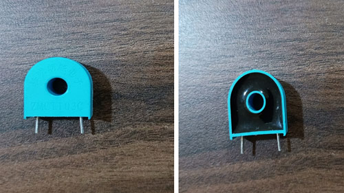
Current Transformer (CT) is a current measuring device used to safely reproduce a low-level current that accurately represents a higher current level for the purpose of metering or protection. CTs are closed loop instruments consisting of a magnetic core and a secondary winding around the core. For this tutorial, we will be using the HWCT-5A/5mA current transformer which is shown below.
How does a Current Transformer Work?
According to Faradays Ampere law, “If a magnetic field is integrated around a close loop of wire, the value of that integral is equal to the net current enclosed by the loop”.
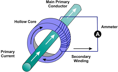
The primary winding of CT, the main loop has the wire with the current we wish to measure passed through the center of the core. The primary winding that carries the main current is said to have a single loop or winding. The wire produces the magnetic field that drives the current on the secondary winding, which is used as output of the CT.
Calculating Current Ratio in Current Transformer
The current on the secondary winding is proportional to the current flowing through the center of the core. Let's suppose the current ratio of CT is 5A:5mA, which means 5 amps on the primary circuit would produce 5 milliamps on the secondary winding.
CT is a type of a transformer so, it must satisfy the amp-turn ratio equation.
Turns Ratio = Np / Ns = Is / Ip
Where,
Np = Turns in Primary winding
Ns = Turns in Secondary winding
Ip = Current in primary winding
Is = Current in secondary winding
Calculation of Ns :
If the current ratio for given CT is 5A:5mA , then
Ns = ( Np * Ip ) / Is
Is =5 mA , Ip = 5 A , Np = 1
So, Ns = 1000
Role of Burden Resistor with Current Transformer
CT burden resistor is a resistor which is connected across the secondary winding of current transformer. The burden resistor is used to protect the current transformer under the open conditions. Secondary winding of CT should be always in a closed circuit to avoid high voltage built up in the second terminal. Secondary winding terminal may be open due to loose connection, cable failure, soldering failure and high voltage will be built across the Secondary winding terminal. So, Burden resistor is used to avoid this type of failure. It is also used to develop some voltage across the secondary windings.
Burden Resistance Calculations
The following calculations can be used to determine a suitable burden resistor for CT. Here, we did not consider the impedance of secondary windings of CT. By considering impedance of Secondary winding, we will get more accurate value of burden resistor.
Burden Resistance=  (Var  *  Ns) /  (2√2  * Ipmax)
Where,
Var  = Analog Reference Voltage of ADC 10 bit which is set to 5.0V
Ns = Num of turns in secondary windings
Ipmax = Maximum primary current will be flown in primary winding
For example –Var  = 5 V , Ns = 1000 , Ipmax = 0.081 Amps
Then, Burden resistance = 22 kΩ
Components Required for AC Current Measurement
The following components required for performing this project-
|
Serial Num |
Component |
Type |
Quantity |
|
1 |
CT |
Window type |
1 |
|
2 |
Arduino uno |
Generic |
1 |
|
3 |
Op-amp LM358 |
IC |
1 |
|
4 |
10K |
Resistor |
1 |
|
5 |
20k |
Resistor |
1 |
|
6 |
1k |
Resistor |
1 |
|
7 |
2k |
Resistor |
1 |
|
8 |
Breadboard |
Generic |
1 |
|
9 |
Jumper wire |
Generic |
10 |
|
10 |
Bulb |
60 watt |
1 |
|
11 |
Capacitor |
Electrolytic |
1 |
|
12 |
AutoTransformer |
0-440 V |
1 |
|
13 |
Zener diode |
Generic |
2 |
|
14 |
Schottky diode |
Generic |
1 |
|
15 |
Multimeter |
Digital |
1 |
|
16 |
LCD display |
16 * 2 |
1 |
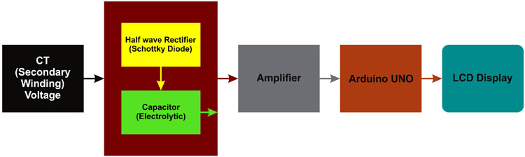
Block Diagram of AC Current Measurement Circuit
The below schematic shows the block diagram for current measurement using the current transformer.
Circuit Diagram to measure AC Current using Arduino
The below schematic shows the Circuit diagram for current measurement using the current transformer.
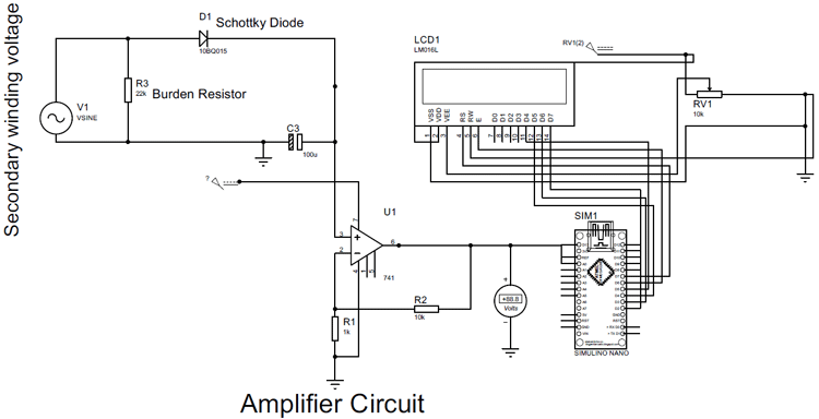
In above circuit, we used 16 * 2 LCD but in project we have used I2C LCD display. For I2C LCD display simply connect.
Arduiono Gnd – I2C Gnd
Arduino 5V - I2C Vcc
Pin A4 - I2C SDA
Pin A5 - I2C SCL
We have used AC voltage source as a Secondary winding voltage in above circuit diagram. This is how Rectifier and amplifier circuit looks like in breadboard.
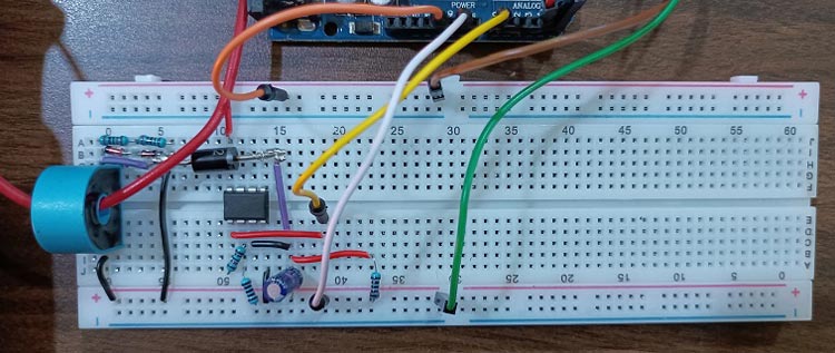
As we can see in this circuit, a red color wire passing through the current transformer, we are going to measure current value passing through this wire. 20k + 2k resistances and Zener diodes are connecting parallel with CT. This resistance is burden resistance of CT (22k) and Zener diodes improve the safety of circuit. Here, we also connected one Schottky diode that will behave as half wave rectifier.
How does Current Measurement Circuit Work?
First of all, both the terminals of the bulb are connected to both the terminal of the transformer and one wire of the bulb passed through the hole present in the middle of the current transformer, this wire acts as the primary winding for the current transformer.
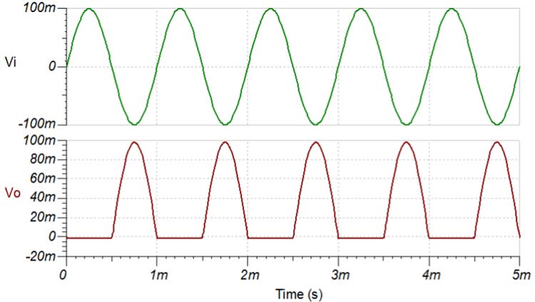
Due to the AC current in the primary winding, AC voltage is induced in the secondary winding as well. Now to convert this AC voltage into DC voltage, it is sent to half wave rectifier, half wave rectifier is forward biased in positive half cycle and reverse biased in negative half cycle. In figure, Vi is input sine wave pulse and Vo is output sine wave pulse.
An electrolytic Capacitor is added to the output of the have wave rectifier to receive only the DC voltage. This capacitor only forwards the DC voltage in the circuit. The output voltage that is obtained from the rectifier circuit is in very less magnitude, so we use amplifier. we have used non inverting operational amplifier with 10k and 1k feedback resistor value.
As we know output of non-inverting operational amplifier is:
Vout = (Rf / R1 + 1 ) Vin
Where,
Rf = Feedback resistor value (10k)
R1 = 1k
Vout = Op-amp output voltage
Vin – Voltage applied at non inverting terminal of op-amp.
After putting all the values in equation we got
Vout = 11 * Vin
11 is close-loop gain for this op-amp. Now, the amplified output voltage is sent to the Arduino, after that, the value of the primary winding current is received in the LCD screen.
Arduino Code for AC Current Measurement
The complete code is given at the end of this document. Here, we are explaining some important parts of the arduino code.
The output of the operational amplifier is an analog voltage value, this analog value is converted into digital value through inbuilt ADC in arduino. The ADC presents on arduino is a 10 bit ADC. It can detect 1024 discrete analog levels. ADC converts analog voltage value into ADC reading using below formula.
Resolution of ADC / System voltage = ADC reading / Analog voltage measured
Resolution for 10bit ADC= 1023
System voltage = 5
Let’s say opamp delivered 2.12 V output voltage to arduion, then
1023 / 5 = ADC reading / 2.12
ADC reading = ( 1023 * 2.12 ) / 5 = 434
The same formula written above is used to print the voltage value in the serial monitor.
The above formula is used to print the voltage value in the serial monitor.
readValue = analogRead(volValue);
 Voltage = (5.0/1023)*readValue;
To convert voltage into current, divide by a constant 10.680, which comes from circuit calculations.
Value = Voltage/10.680;
To print the primary winding current value in LCD display, wire.h, LiquidCrystal_I2C libraries are used.
#include <Wire.h>
#include <LiquidCrystal_I2C.h>
Set the LCD address to 0 * 27 for a 16 chars and 2 lines display.
LiquidCrystal_I2C lcd(0x27, 16, 2);
Code:
#include <Wire.h>
#include <LiquidCrystal_I2C.h>
LiquidCrystal_I2C lcd(0x27, 16, 2);
int volValue=A0;
int readValue;
float Value;
float Voltage;
int LED = 13;
void setup(){
lcd.begin();
lcd.backlight();
pinMode(LED, OUTPUT);
pinMode(volValue,INPUT);
Serial.begin(9600);
 }
void loop(){
readValue = analogRead(volValue);
  Voltage = (5./1023)*readValue;
  Value = Voltage/10.680;
Serial.println(Value);
lcd.clear();
lcd.setCursor(0,0);
lcd.print("Current in Wire");
lcd.setCursor(6,1);
lcd.print(Value);
delay(1000);
}
Output of AC Current Measurement Circuit
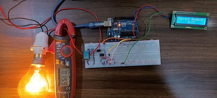
As the voltage is varied from the Auto transformer, the value of the current in the primary winding changes, which we measure with a digital multimeter.
Change in the value of the primary winding current is also visible in the LCD screen. As we can see in the image below, the actual current value and measured current value is almost same.
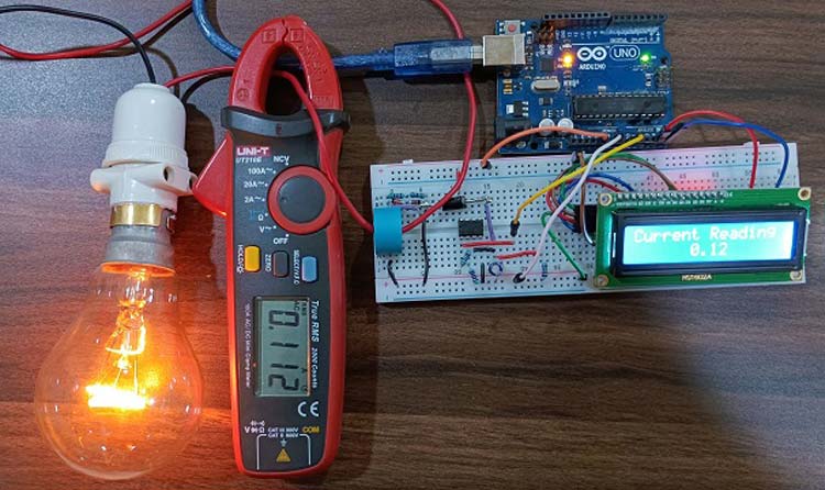
Measuring a smaller value (less than 0.2 A) of current shows a fluctuation in measured current value at second decimal place. This happens because of the very small value of AC current but if we measure a large value (more than 0.5A) of current, then fluctuation does not appear. Here, we used metal film resistor but we can get more accurate results by using precision metal film resistor.
#include <Wire.h>
#include <LiquidCrystal_I2C.h>
LiquidCrystal_I2C lcd(0x27, 16, 2);
int volValue=A0;
int readValue;
float Value;
float Voltage;
int LED = 13;
void setup(){
lcd.begin();
lcd.backlight();
pinMode(LED, OUTPUT);
pinMode(volValue,INPUT);
Serial.begin(9600);
}
void loop(){
readValue = analogRead(volValue);
Voltage = (5./1023)*readValue;
Value = Voltage/10.680;
Serial.println(Value);
lcd.clear();
lcd.setCursor(0,0);
lcd.print("Current in Wire");
lcd.setCursor(6,1);
lcd.print(Value);
delay(1000);
}


