


Flood is a major known natural disaster that causes a huge amount of loss to the environment and living beings. So in these conditions, it is most crucial to get the emergency alerts of water level status at river beds in different conditions. In this project, the objective is to sense the water levels at river beds and check whether they are at a normal condition or not. If they reach beyond the limit, then it alerts the people through LED indications as well as through internet application. Here we are using an ultrasonic sensor to sense the river levels and a NodeMCU ESP8266 to process these data. The data will be uploaded to ThingSpeak IoT cloud, using which the river levels can be graphically monitored from anywhere in the world.
Components Required
- ESP8266 NodeMCU
- Ultrasonic Sensor
- Power supply
- LEDs (Red & Green)
- Breadboard
- Jumpers
Working of Flood Monitoring System
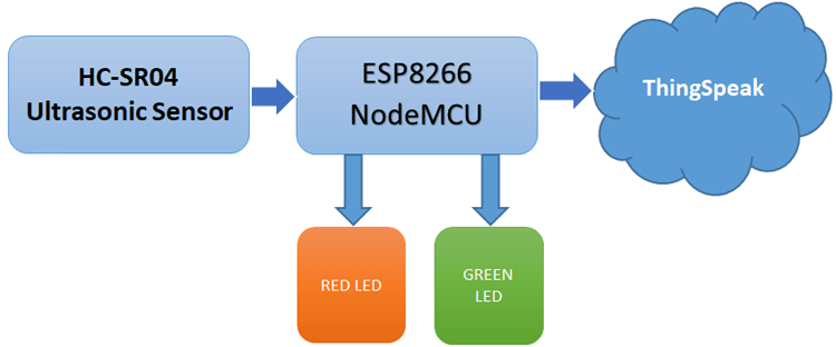
We previously used ESP8266 NodeMCU to build many IoT projects. The above block diagram shows the working of this IoT based flood monitoring system. Here, the ultrasonic sensor is used to sense the water level of the river. The data output from the ultrasonic sensor is fed to the NodeMCU, where it is processed and sent to ThingSpeak for Graphical monitoring and Critical alert. Here, a red LED is used to alert during the critical flood conditions, and the Green LED is used to indicate the normal condition.
HC-SR04 Ultrasonic Sensor
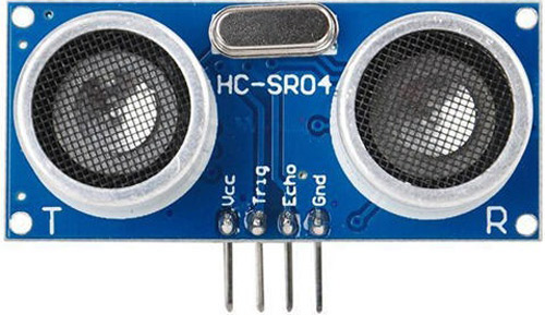
The ultrasonic sensor works on the principle of ultrasound waves which is used to determine the distance to an object. An ultrasonic sensor generates high-frequency sound waves. When this ultrasound hits the object, it reflects as echo which is sensed by the receiver. By using the time required for the echo to reach the receiver, we can calculate the distance to an object we are targeting.
Distance= (Time x Speed of Sound in Air (340 m/s))/2
Ultrasonic distance sensor consists of two ultrasonic transducers. Among them, one acts as a transmitter which converts the electrical pulse of microcontroller into ultrasonic sound pulse and the receiver receives for the transmitted pulses. If it receives them, then it produces an output pulse whose time period can be used to determine the distance from the object.
Features
- Working Voltage: 5V
- Working Current: 15mA
- Working Frequency: 40HZ
- Measuring Distance: 2cm-4m
- Measuring Angle: 15 Deg.
- Triggering input pulse: 10uS
Learn more about the ultrasonic sensor by going through its previous projects like IoT Inventory management and Wi-Fi controlled robot.
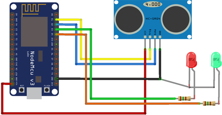
Flood Monitoring System Circuit Diagram
Circuit diagram for flood monitoring system is given below
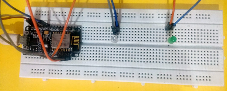
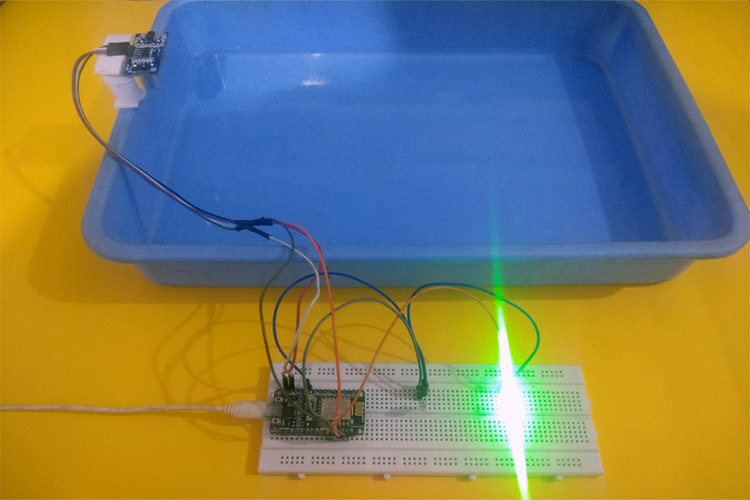
The real setup will look like this:
Setup ThingSpeak account for Flood Monitoring and Alerting System
After successful completion of hardware as per the above circuit diagram, now its time to setup the IoT platform, where the data can be stored to monitor online. Here we are using ThingSpeak to store the data, which is a very popular IoT cloud platform used to build the store, monitor, and process data online. We also used ThingSpeak to build many IoT based projects.
Step 1: Sign up for ThingSpeak
First, go to https://thingspeak.com/ and create a new free Mathworks account if you don’t have a Mathworks account before.
Step 2: Sign in to ThingSpeak
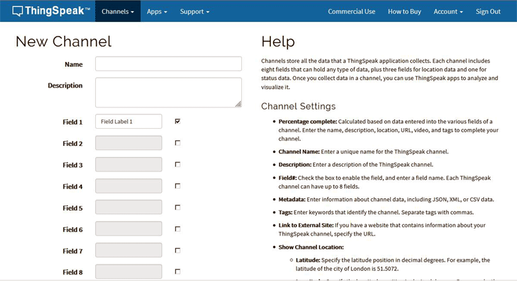
Sign in to ThingSpeak using your credentials and click on “New Channel”. Now fill up the details of the project like Name, Field names, etc. Here we have to create four field names such as Humidity, Temperature, pressure & Rain. Then click on “Save channel”.
Step 3: Record the Credentials
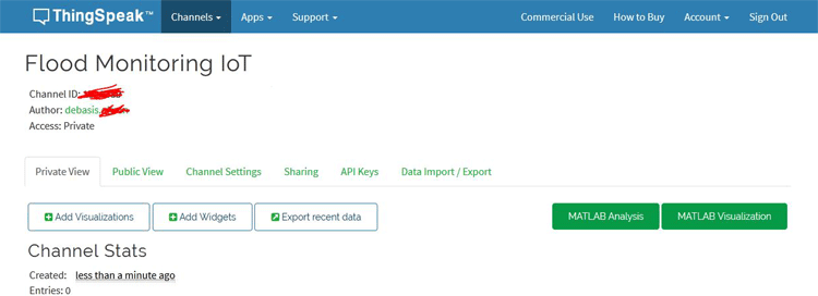
Select the created channel and record the following credentials.
- Channel ID, which is at the top of the channel view.
- Write an API key, which can be found on the API Keys tab of your channel view.
Step 4: Add widgets to your GUI
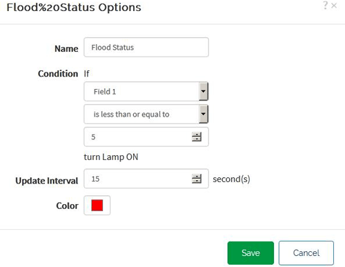
Click on “Add Widgets” and add four appropriate widgets like gauges, numeric displays, and indicators. In my case, I have taken an Indicator for the flood. Select appropriate field names for each widget.
Code Explanation
After the successful completion of the hardware setup, now it’s time for programming the ESP8266 NodeMCU.
To upload code into NodeMCU using Arduino IDE, follow the steps below:
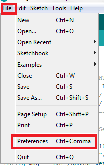
1. Open Arduino IDE, then go to File–>Preferences–>Settings.
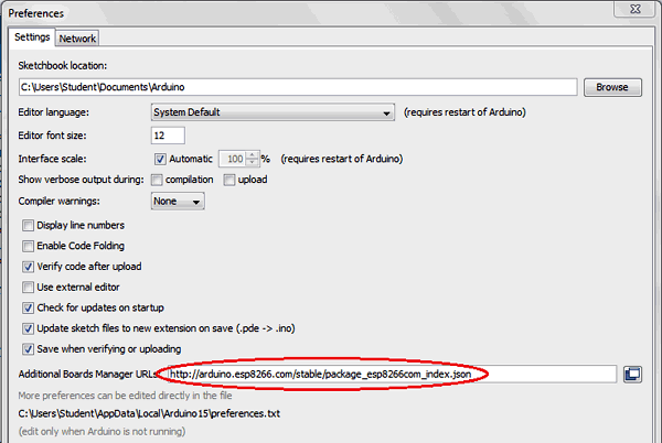
2. Type https://arduino.esp8266.com/stable/package_esp8266com_index.json in the ‘Additional Board Manager URL’ field and click ‘Ok’.
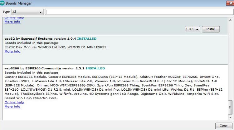
3. Now go to Tools > Board > Boards Manager. In the Boards Manager window, Type ESP8266 in the search box, select the latest version of the board, and click on install.
4. After installation is complete, go to Tools ->Board -> and select NodeMCU 1.0(ESP-12E Module). Now you can program NodeMCU with Arduino IDE.
After the above setup for programming NodeMCU using Arduino IDE, upload the complete code into ESP8266 NodeMCU. The stepwise explanation of the complete code is given below.
Start the code by including all the required library files in the code like ESP8266WiFi.h for ESP8266 board, etc. Here, ThingSpeak.h library is used for ThingSpeak platform, which can be added to Arduino IDE using the steps below:
- In the Arduino IDE, choose Sketch/Include Library/Manage Libraries.
- Click the ThingSpeak Library from the list, and click the Install button.
#include "ThingSpeak.h"
#include <ESP8266WiFi.h>
Next, define the pins which are used for the ultrasonic sensors and LEDs.
const int trigPin1 = D1;
const int echoPin1 = D2;
#define redled D3
#define grnled D4
Now, the network credentials- i.e. SSID and password are defined, which are required to connect the NodeMCU with the internet. Then the ThingSpeak account credentials such as the channel number and write API are defined, which were recorded earlier. Make sure, you have edited your credentials in place of these variables.
unsigned long ch_no = 102xxxx;
const char * write_api = "SXSSSSS";
char auth[] = "fuEERRXXXXXXXXXXXXXX";
char ssid[] = "admin";
char pass[] = "";
Then, the variables for timing purposes are defined.
unsigned long startMillis;
unsigned long currentMillis;
const unsigned long period = 10000;
Then, to connect NodeMCU to the internet, call WiFi.begin and pass network SSID and password as its arguments. Check for the successful network connection using WiFi.status() and after a successful connection, print a message on Serial Monitor with the local IP address.
WiFi.begin(ssid, password);
while (WiFi.status() != WL_CONNECTED)
  {
    delay(500);
    Serial.print(".");
  }
  Serial.println("WiFi connected");
  Serial.println(WiFi.localIP());
Then connect to the ThingSpeak platform using saved credentials. For this, ThingSpeak.begin is used.
ThingSpeak.begin(client);
For calculating the distance, an input pulse is given to the sensor through the trig pin of the Ultrasonic sensor. Here as per the HC-SR04 datasheet, a 2-microsecond pulse is given, then from the echo pin, the output pulse of the sensor is read and the distance is calculated in centimeter.
  digitalWrite(trigPin1, LOW);
  delayMicroseconds(2);
  digitalWrite(trigPin1, HIGH);
  delayMicroseconds(10);
  digitalWrite(trigPin1, LOW);
  duration1 = pulseIn(echoPin1, HIGH);
  distance1 = duration1 * 0.034 / 2;
Then, an if-else condition is written for the LED indications at both Normal condition and Flood conditions. Here as per my setup, I have taken 4 cm as reference. You can change it as per your set-up.
if (distance1 <= 4)
  {
    digitalWrite(D3, HIGH);
    digitalWrite(D4, LOW);
  }
  else
  {
    digitalWrite(D4, HIGH);
    digitalWrite(D3, LOW);
  }
Finally, the value to the river level is uploaded to the ThingSpeak channel in each 10 seconds interval.
if (currentMillis - startMillis >= period)
  {
    ThingSpeak.setField(1, distance1);
    ThingSpeak.writeFields(ch_no, write_api);
    startMillis = currentMillis;
  }
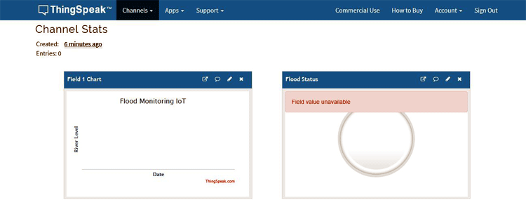
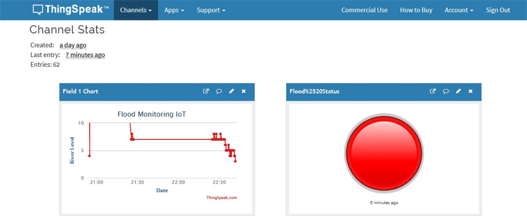
ThingSpeak will show a big red circle in case of Flood like shown below:
This is just a basic model for IoT based flood monitoring and alerting system, and there is a lot of scope for improvement. I hope you like the project and learned something new out of it.
Complete code and video for this project are given below.
#include "ThingSpeak.h"
#include <ESP8266WiFi.h>
const int trigPin1 = D1;
const int echoPin1 = D2;
#define redled D3
#define grnled D4
unsigned long ch_no = 1026389;//Replace with Thingspeak Channel number
const char * write_api = "XK88XXXXXXX";//Replace with Thingspeak write API
char auth[] = "fu0o5JaLXXXXXXXXXXXXXXXX";
char ssid[] = "admin";
char pass[] = "";
unsigned long startMillis;
unsigned long currentMillis;
const unsigned long period = 10000;
WiFiClient client;
long duration1;
int distance1;
void setup()
{
pinMode(trigPin1, OUTPUT);
pinMode(echoPin1, INPUT);
pinMode(redled, OUTPUT);
pinMode(grnled, OUTPUT);
digitalWrite(redled, LOW);
digitalWrite(grnled, LOW);
Serial.begin(9600);
WiFi.begin(ssid, pass);
while (WiFi.status() != WL_CONNECTED)
{
delay(500);
Serial.print(".");
}
Serial.println("WiFi connected");
Serial.println(WiFi.localIP());
ThingSpeak.begin(client);
startMillis = millis(); //initial start time
}
void loop()
{
digitalWrite(trigPin1, LOW);
delayMicroseconds(2);
digitalWrite(trigPin1, HIGH);
delayMicroseconds(10);
digitalWrite(trigPin1, LOW);
duration1 = pulseIn(echoPin1, HIGH);
distance1 = duration1 * 0.034 / 2;
Serial.println(distance1);
if (distance1 <= 4)
{
digitalWrite(D3, HIGH);
digitalWrite(D4, LOW);
}
else
{
digitalWrite(D4, HIGH);
digitalWrite(D3, LOW);
}
currentMillis = millis();
if (currentMillis - startMillis >= period)
{
ThingSpeak.setField(1, distance1);
ThingSpeak.writeFields(ch_no, write_api);
startMillis = currentMillis;
}
}


