


As always, we are aware of the use of measuring heartbeats in Medical Science to diagnose various problems. Heartbeats uses to monitor the health condition of our heart. It is an ancient part of medical science to measure the current heartbeats of patients for diagnosing problems. So, in this project, we going to build an IoT based monitoring system using NodeMCU ESP8266 that will able to measure the current heartbeats and publish the data to the cloud platform. Hence the data can be accessed from anywhere around the globe (only required Internet connection). This project helps to provide high-quality support to patients & make things easier for medical staff. Normal people can also use this as a part of their life to monitor their heart health.
We built many projects using ESP8266, here are some examples,
- How to build LoRa Based GPS Tracker Using ESP8266
- IoT Based Inventory Management System using Load Cell and NodeMCU
- IoT based Voice Controlled Neopixel LED – Set any Colour using Voice Commands on Google Assistant
- IoT Based Colour Sorting Machine using ESP8266 and ThingSpeak
Components Required
- ESP8266 NodeMCU Board
- OLED Display
- Heartbeat Sensor Module
- Breadboard
- Jumper Wires
- LED Lights
Pulse Sensor
It is an Analog device that is used to measure the pulses/heartbeat of the human body. It monitors the change of blood in the blood vessels by emitting & sensing the light, the process is known as photoplethysmography.
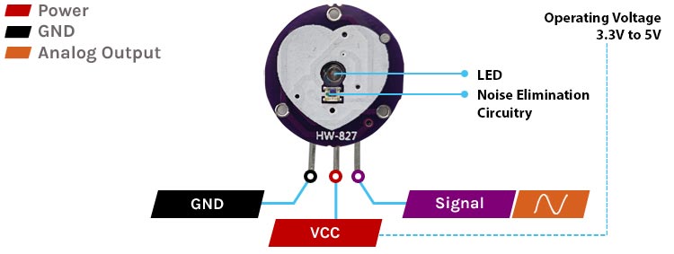
It has three pins GND, VCC, and signal.
- VCC pin: This pin is used to supply power to the sensor to make it work. It is typically connected to the 3.3V pin on the NodeMCU board. Its voltage range lies between 3.3v to 5v.
- GND pin: This pin is used to connect the sensor and the ground of the NodeMCU board.
- Signal pin: This pin is used to transmit the pulse rate data in analog form to the NodeMCU board.
OLED Display
Organic Light _Emitting Diode(OLED) Displays are used to display the output data. They are extremely light, paper-thin, theoretically flexible, and produce a brighter, crisper image.
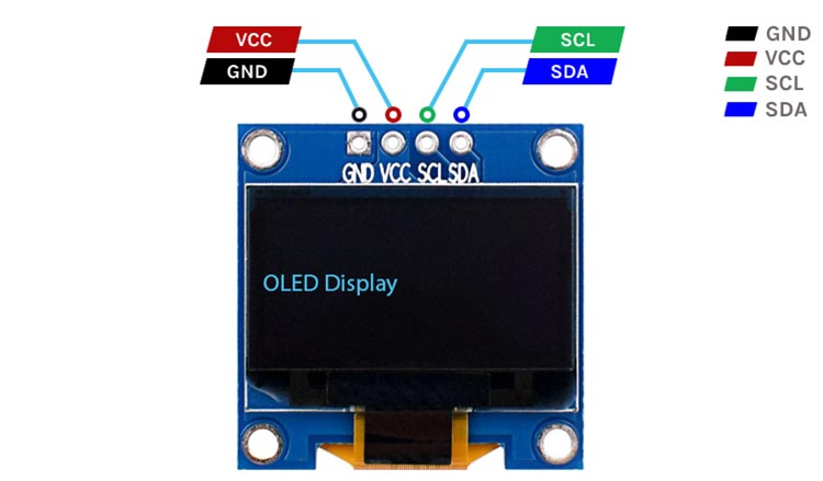
It has four pins VCC, GND, SCl, and SDA.
- VCC pin: This pin is used to supply the voltage to the OLED display to turn on the display. The voltage range of OLED lies from 3.3v to 6v.
- GND pin: This pin is used to connect the display to the ground of the NodeMCU board.
- SDA pin: This pin is used for data transmission in I2C communication. It is typically connected to the D2 pin on the NodeMCU board.
- SCL pin: This pin is used for clock signals in I2C communication. It is typically connected to the D1 pin on the NodeMCU board.
Circuit Diagram
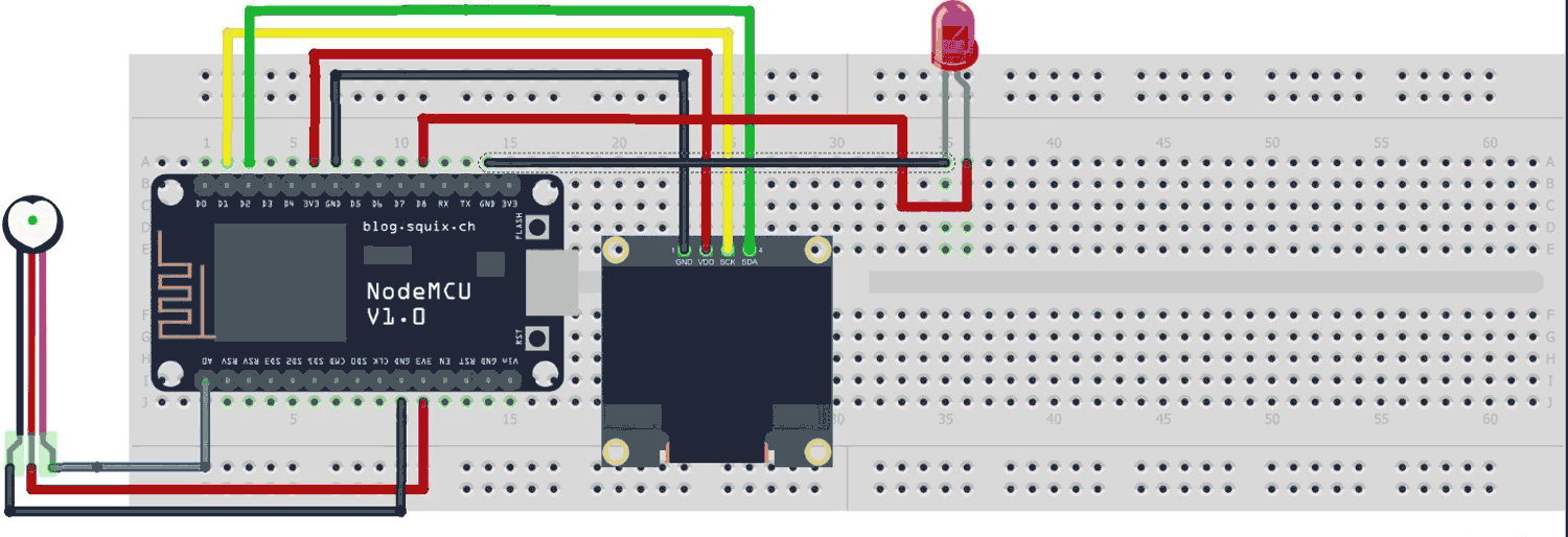
Here, the connections are pretty simple. The pulse sensor signal pin is connected to A0 of NodeMCU. The SCL & SDA of OLED should be connected to D1 & D2 of NodeMCU respectively.
Also, the RED LED indicating the positive side of the pulse is connected to the D8 pin of NodeMCU and the other side to the ground.
Setting up Thingspeak for Remote Monitoring
To monitor the output data over the cloud, we will be using the Thingspeak cloud platform. There we will create a field for storing the heartbeats data. Let’s set it up quickly.
- First of all, create a new account on the Thingspeak website.
- Then login into your account and create a new channel. Channels have read and write API keys and can be public or private.
- Give a name to a field in the channel and use it for data monitoring.
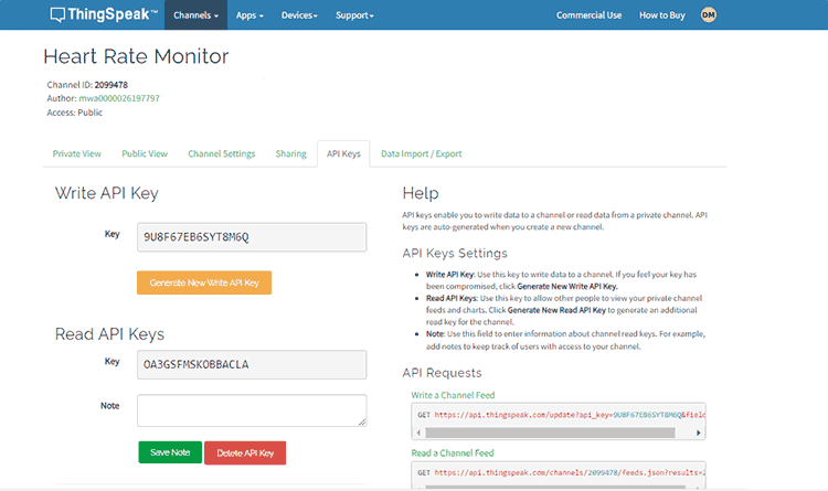
- Inside the channel go to API keys and copy it. API keys are different for different channels, we need to use them in Code to provide access to the channel with channel ID.
- There are Read & Write both API keys. If you want to send & Receive data to Thingspeak, use the write & read API keys respectively.
Project Code Explanation
The program reads the analog parameters of the pulse sensor and converts it to BPM (Beats per Minute) and displays data to OLED as well as on a cloud Platform (Thingspeak).
Firstly, we have to include all necessary Libraries for the successful execution of the code. Libraries include SPI, WIRE, Adafruit_SSD1306, and Adafruit_GFX. ESP8266WiFi, ThingSpeak. Also, we have defined the necessary variables and objects for further programming.
#include <SPI.h>
#include <Wire.h>
#include <Adafruit_SSD1306.h>
#include <Adafruit_GFX.h>
#include <ESP8266WiFi.h>
#include <ThingSpeak.h>
Adafruit_SSD1306 display (128,64, &Wire);
WiFiClient client;
const int sensorPin = A0;                             // A0 is the input pin for the heart rate sensor
int sensorValue;                                        // Variable to store the value coming from the sensor
int count = 0;
unsigned long starttime = 0;
int heartrate = 0;
boolean counted = false;
long myChannelNumber = 2099478;
const char myWriteAPIKey[] = "9U8F67EB6SYT8M6Q";
- The SSD1306 controller of the OLED display has complex drivers, hence we are using the predefined library Adafruit SSD1306 to hide the complexities of the controller.
- The Adafruit_SSD1306 constructor accepts three arguments: screen width, screen height, and the ESP8266 pin number to which the display’s reset pin is connected. But here we have not connected any RESET pin.
Adafruit_SSD1306 display (128,64, &Wire);
- To display graphics primitives like circles, lines, and squares on OLED. We must have to use Adafruit GFX Library.
- ESP8266WiFi library used to connect the WIFI module to the WIFI connection by providing connection information.
- Thingspeak library used to connect to the Thingspeak server over the Internet which allows us to Send & Receive Data.
You can install all these libraries from Arduino IDE by going to Sketch > Include Library > Manage Libraries.
- A0 pin reads the analog data from the pulse sensor.
- Variables MychannelNumber & mywriteAPIkey is the channel ID & API KEY of the channel of the Thingspeak account respectively, where you will be going to publish the data. You need to change these two-variable data in order to successfully send the data.
void setup (void)
  { display.begin(SSD1306_SWITCHCAPVCC, 0x3C);
    pinMode (D8, OUTPUT);                              // D8 LED as Status Indicator
    Serial.begin (115200);                             // Start Serial Communication @ 115200
    display.clearDisplay();
    WiFi.begin("Semicon Media 2.4", "cdfiP29to665");
      while(WiFi.status() != WL_CONNECTED)
      {delay(200);
        Serial.print("..");}
      Serial.println();
      Serial.println("NodeMCU is connected!");
      Serial.println(WiFi.localIP());
      ThingSpeak.begin(client);
    }
In the setup() function, serial communication is initiated.
- The OLED display is initialized with the begin(SSD1306_SWITCHCAPVCC, 0x3C) function where SSD1306_SWITCHCAPVCC turns ON the internal charge circuit and display output, and 0x3C is the I2C address of the display.
- clearDisplay() function used to clear the display and make it fully Blank.
- The WiFi.begin() function is used to initialize the WIFI connection Process. It takes two parameters WIFI Name & password of the same network.
- ThingSpeak.begin() function associated with the Thingspeak library, it initializes the connection process to connect to the Thingspeak server.
void loop ()
  { starttime = millis();
    while (millis()<starttime+20000)                                            // Reading pulse sensor for 20 seconds
    { sensorValue = analogRead(sensorPin);
        //Serial.println (sensorValue);
          delay(50);
      if ((sensorValue >= 590 && sensorValue <=680) && counted == false)    // Threshold value is 590 (~ 2.7V)
      {  count++;
        digitalWrite (D8,HIGH);
          delay (10);
        digitalWrite (D8, LOW);
        counted = true;
        }
      else if (sensorValue < 590)
       {  counted = false;
          digitalWrite (D8, LOW);
          }
      }
    Serial.print ("Pulse ");
    Serial.println (count);
    heartrate = (count)*3;                              // Multiply the count by 3 to get beats per minute
    Serial.println ();
    Serial.print ("BPM = ");
    Serial.println (heartrate);                         // Display BPM in the Serial Monitor
    Serial.println ();
    count = 0;
    display.clearDisplay();
    display.setTextColor(WHITE);
    display.setCursor(0,0);
    display.setTextSize(2);
    display.println("Heart Rate");
    display.setCursor(0,28);
    display.print("BPM: ");
    display.print(heartrate);
    display.display();
    ThingSpeak.writeField(myChannelNumber, 1, heartrate, myWriteAPIKey);
    //delay(1000);
}
In the Above loop part, we have done all the processing tasks like comparison and value assignment along with running the Thingspeak function.
- Variable sensorValue stores the analog input of the pulse sensor. Then we are comparing the value within the limit >=590 & <=680 to detect the beats.
- If beats are detected then the LED at the D8 pin turns ON for 10ms else it will not glow.
BPM calculation:
- We counted pulse for 20 seconds and then multiplied it by 3 times to get Beats per minute which was displayed on the serial monitor in Arduino IDE.
OLED Display: Many functions are used to adjust the display according to requirements. Let’s see some of the used functions.
- setTextColor used to set font color. Pass WHITE for a dark background and BLACK for a bright one.
- setCursor takes two parameters of the location of the x-axis and y-axis and assigns the cursor to the location.
- setTextSize is used to set the font size (starting from 1).
- display() command to instruct the library to bulk transfer the screen buffer to the SSD1306 controller’s internal memory and display the contents on the OLED screen.
At last, we use Thingspeak’s writefield() function. It takes four arguments starting with channel ID, Field Number, Data variable, and API Key. All this information should be as per your Thingspeak account and channel.
The complete code you will find below in the code section.
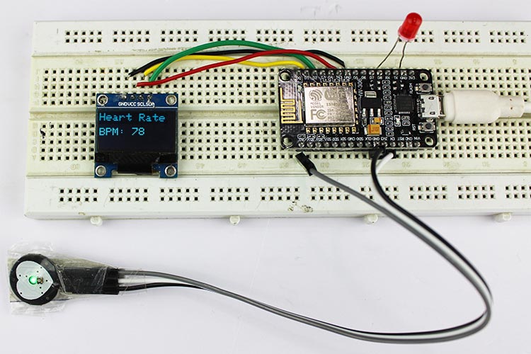
Working of Project
Now that you have understood the code, you can simply upload it to your NodeMCU board and the project should start working.
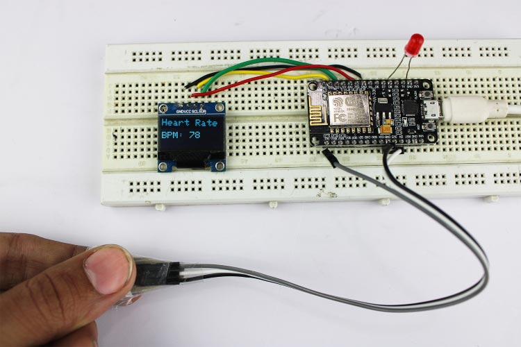
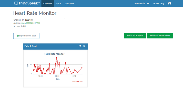
Monitor your heartbeats on OLED as well as on the cloud.
Hope you enjoyed the article and learned something useful from it. If you have any questions, you can leave them in the comment section below.
#include <SPI.h>
#include <Wire.h>
#include <Adafruit_SSD1306.h>
#include <Adafruit_GFX.h>
#include <ESP8266WiFi.h>
#include <ThingSpeak.h>
Adafruit_SSD1306 display(128,64,&Wire);
WiFiClient client;
const int sensorPin = A0; // A0 is the input pin for the heart rate sensor
int sensorValue; // Variable to store the value coming from the sensor
int count = 0;
unsigned long starttime = 0;
int heartrate = 0;
boolean counted = false;
long myChannelNumber = 2099478;
const char myWriteAPIKey[] = "9U8F67EB6SYT8M6Q";
void setup (void)
{ display.begin(SSD1306_SWITCHCAPVCC, 0x3C);
pinMode (D8, OUTPUT); // D8 LED as Status Indicator
Serial.begin (115200); // Start Serial Communication @ 115200
display.clearDisplay();
WiFi.begin("Semicon Media 2.4", "cdfiP29to665");
while(WiFi.status() != WL_CONNECTED)
{delay(200);
Serial.print("..");}
Serial.println();
Serial.println("NodeMCU is connected!");
Serial.println(WiFi.localIP());
ThingSpeak.begin(client);
}
void loop ()
{ starttime = millis();
while (millis()<starttime+20000) // Reading pulse sensor for 20 seconds
{ sensorValue = analogRead(sensorPin);
//Serial.println (sensorValue);
delay(50);
if ((sensorValue >= 590 && sensorValue <=680) && counted == false) // Threshold value is 590 (~ 2.7V)
{ count++;
digitalWrite (D8,HIGH);
delay (10);
digitalWrite (D8, LOW);
counted = true;
}
else if (sensorValue < 590)
{ counted = false;
digitalWrite (D8, LOW);
}
}
Serial.print ("Pulse ");
Serial.println (count);
heartrate = (count)*3; // Multiply the count by 3 to get beats per minute
Serial.println ();
Serial.print ("BPM = ");
Serial.println (heartrate); // Display BPM in the Serial Monitor
Serial.println ();
count = 0;
display.clearDisplay();
display.setTextColor(WHITE);
display.setCursor(0,0);
display.setTextSize(2);
display.println("Heart Rate");
display.setCursor(0,28);
display.print("BPM: ");
display.print(heartrate);
display.display();
ThingSpeak.writeField(myChannelNumber, 1, heartrate, myWriteAPIKey);
}


