


The LoRa technology penetration around the world is increasing and because of their ability to run on very minimal power, LoRa devices can be ideal for battery-intensive applications like remote weather monitoring, remote sensing, and tracking. We have earlier seen how we can integrate the HPD13A Lora Module with Arduino to Establish Communication with The Things Network and send temperature data onto the TTN Server.
In this project, we will be building a GPS Tracker using the Lora module HPD13A. Our aim will be to send live GPS Coordinates to The Things Network, as well as use Webhooks integrations available with The Things Network to get a visualization of the data.
Components Required
- HPD13A LoRa Module
- Neo 6M GPS Module
- ESP8266 NodeMCU Dev Board
- LM2596 Setup-down Converter.
- Access To a LoRa Gateway Nearby
How does this LoRa GPS Tracker Project work?
We have discussed before how the LoRa technology is ideal for low-power applications. To connect any LoRa module with The Things Network, the primary requirement is a LoRa gateway nearby, if you have your own LoRa gateway, you can refer to our previous article on How To Configure a LoRa Gateway In India. You can also check the active LoRa Gateways in your vicinity from the Things Network Website: www.thethingsnetwork.org/map. Once we’re sure that we have a working LoRa gateway in our vicinity, we can proceed with the project.
![]()
The working of this project is very simple, we have the ESP8266 acting as the main controller. The ESP8266 parses data from the Neo-6M GPS Module and converts the Latitude and Longitude into a LoRa Packet, this LoRa packet is then sent to the HPD13A LoRa module which connects to the nearby gateway. Once it is connected to a LoRa gateway, this LoRa packet gets sent to The Things Network. You can view this raw data on your Things Network Dashboard but for this project, we will create a webhook integration that will allow us to send the position data to Ubidots. Using this data on Ubidots, we can create a map interface to plot our tracking data.
ESP8266 LoRa GPS Tracker Circuit Diagram
![]()
The connections of this Nodemcu LoRa GPS Tracker are simple, we have used an LM2596 Step-Down Converter to take an input of range 9-12V from a Li-Po Battery and step it down to 4.2V to drive the ESP8266 and the Neo-6M GPS Module. The LoRa module will be driven by the 3.3V from the ESP8266 and will communicate via the SPI Pins.
Note: Since the Neo-6M is connected to the hardware serial pins of the ESP8266, you will have to keep the Neo-6M disconnected while uploading the code on the ESP8266.
Setup End Device on The Things Network
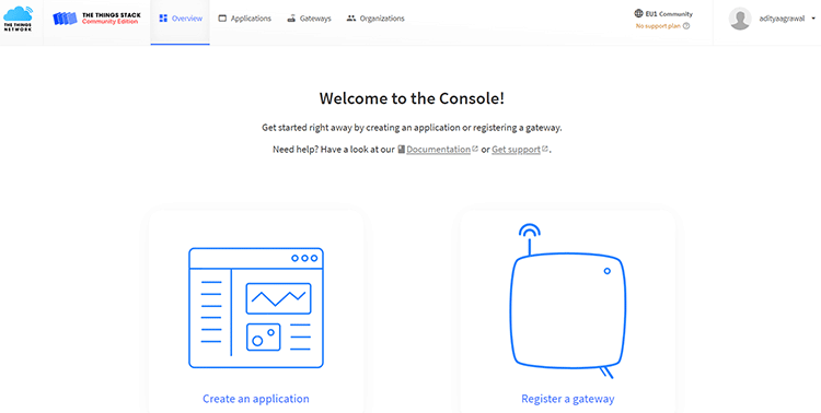
Let’s get started by Signing Up on The Things Network. You can create an individual or a student account, both of which are free of charge. When selecting the LoRa Cluster, you can select the EU Cluster if you’re not based in North America or Australia. Once you have created your account and completed the email verification, you will be able to access the TTN Console, which would look like this.
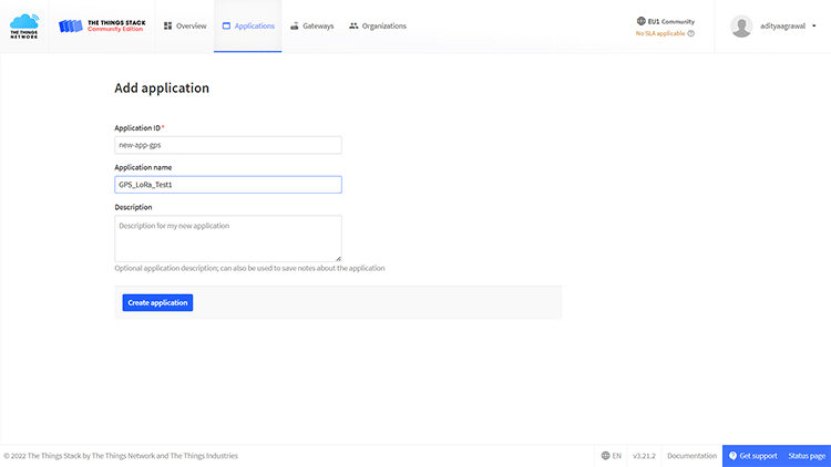
Click on create an application. Enter a unique application ID and application name and click on create.
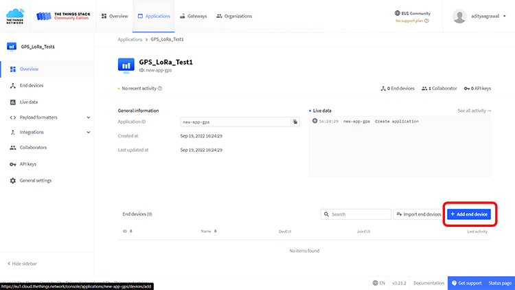
Once your application is created, click on the add end device.
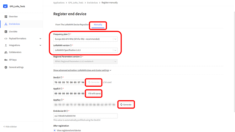
Click on the “Manually” Tab, Enter the following parameters, generate the DevUI, AppEUI, and AppKey, and complete the end device creation.
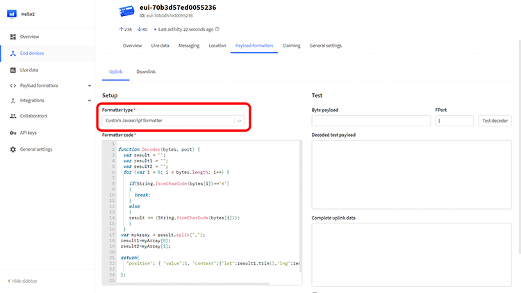
Once the device is created, switch to the “Payload Formatters” Tab.

Under the Formatters Type option select “Custom Javascript formatter” and paste the following code.
function Decoder(bytes, port) {
  var result = "";
  var result1 = "";
  var result2 = "";
  for (var i = 0; i < bytes.length; i++) {
    if(String.fromCharCode(bytes[i])=='X') {
      break;
    }
    else {
      result += (String.fromCharCode(bytes[i]));
    }
  }
 var myArray = result.split(",");
 result1=myArray[0];
 result2=myArray[1];
 return {
   "position": { "value":1, "context":{"lat":result1.trim(),"lng":result2.trim()}}
 };
}
Our end device configuration on The Things network is done and we now move to burning the Arduino code.
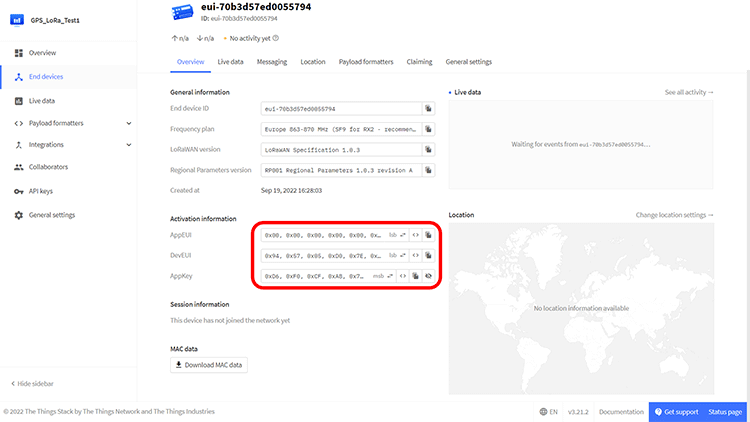
Open the device overview and copy the DevUI, AppEUI, and the AppKey. Make sure that the LSB order is set for DevUI, AppEUI and the MSB order is set for AppKey.
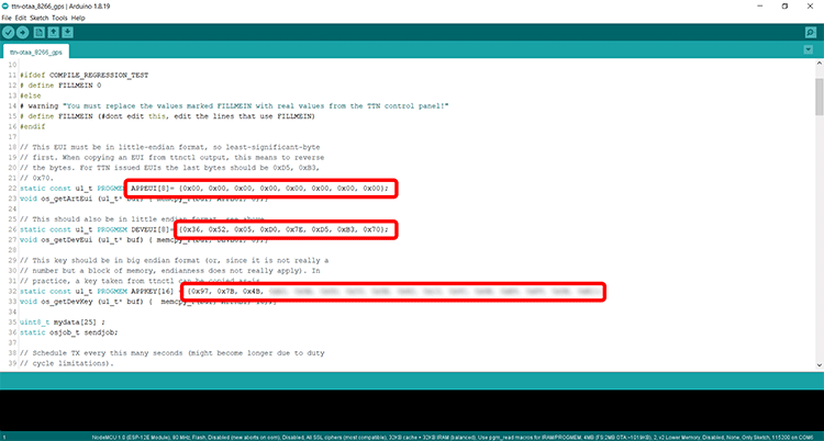
Open the Arduino code attached and simply paste your IDs in their respective fields.
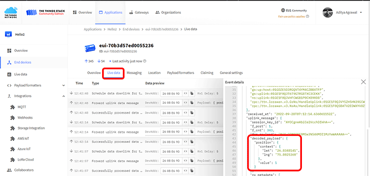
Once you upload the Arduino code, your device will start the LoRa transmission to The Things Network and this can be viewed in the “Live Data” Tab.
Setting Up Ubidots Connection For Data Visualization
Now that we have our data coming to TTN, we will use the integration options to integrate a Ubidots Dashboard with this data. Since our data is primarily Latitude and Longitude Coordinates, we can use the Maps Widget offered by Ubidots. To get started, simply create a Ubidots STEM account and open your dashboard.
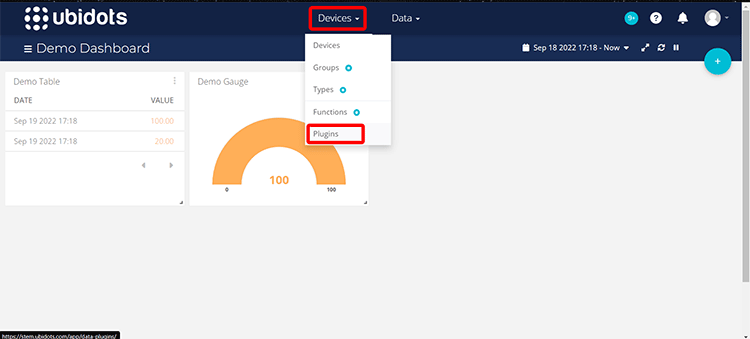
In the Devices Menu, select Plugins.
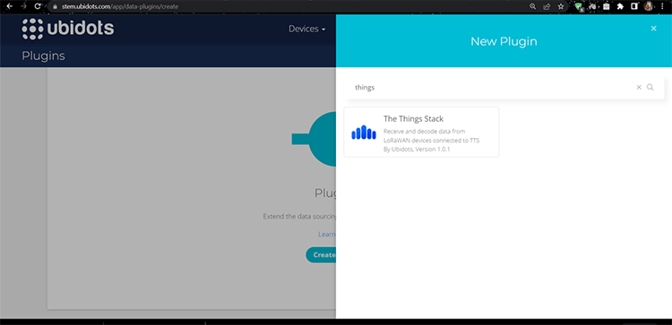
Amongst the given options, we will search and select the “The Things Stack” option.
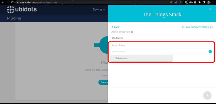
You can leave most of the settings to default and select the Ubidots Token as Default Token
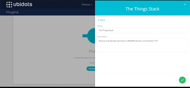
Once you’ve added the name and description of your plug-in, click on create.
Your plugin will now be live, we will now click on the edit plugin option.
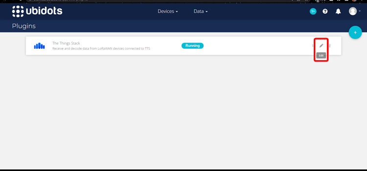
Under the decoder settings, we have the HTTPs Endpoint URL, this is the URL on which we will configure the TTN Server to send data packets, and copy the Plugin ID which is the portion of URL after the /api/webhook/ portion.
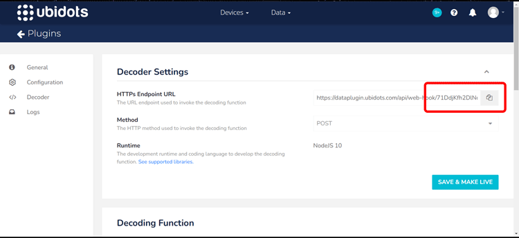
Once this is done, scroll down to the Decoder Function panel and uncomment the following line of code.
var decoded_payload = args['uplink_message']['decoded_payload'];
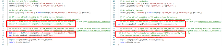
Also, comment the following two lines.
let bytes =  Buffer.from(args['uplink_message']['frm_payload'], 'base64');
var decoded_payload = decodeUplink(bytes)['data'];
The changes would look similar to this.
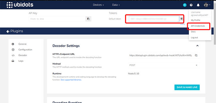
Click on the Save & Make Live button. Our integration is now ready from the Ubidots side, before moving to TTN. We need to click on the API credentials option on our profile menu and copy the default token. This will be used later.
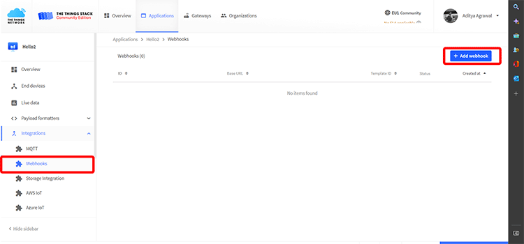
Open your TTN Application and on the Integrations panel, select Webhooks. And click on the Add Webhook button.
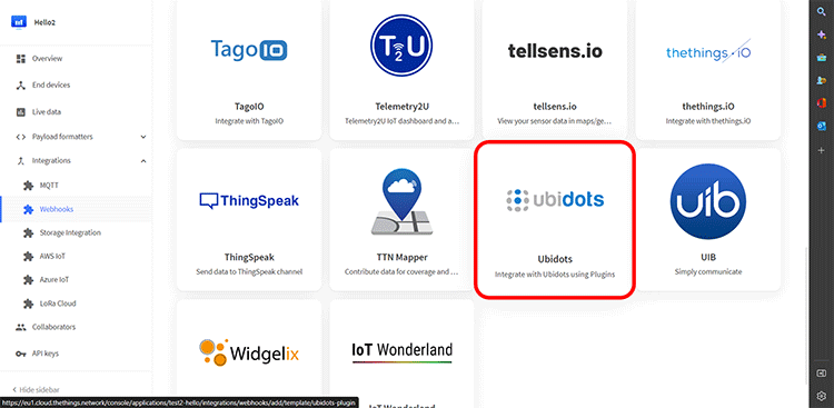
Amongst all the listed options, select the Ubidots plugin.
You now need to enter your Plugin ID as mentioned above and your Ubidots Token.
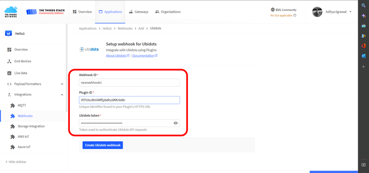
This will successfully create an integration webhook.
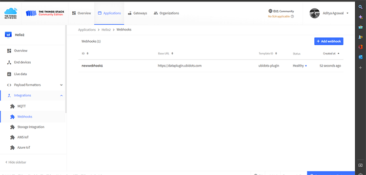
Once this integration is done, our LoRa device will send data to the TTN Server which will automatically be directed to the Ubidots Server. You can open your Ubidots dashboard and under the Devices page, our device will become automatically visible.

We can now do the final step of adding a Map Widget on the dashboard. Under the Data Tab, Click on Dashboards to open your Dashboard. Click on the Create Widget Button.
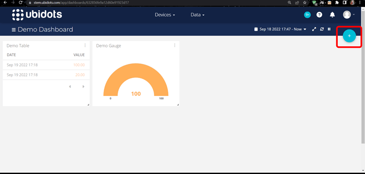
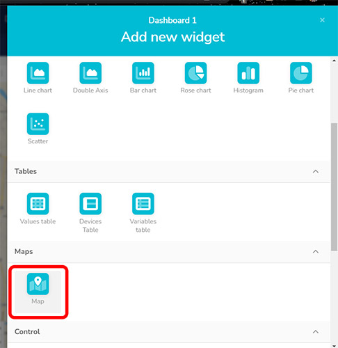
In the Add new Widget menu, you will see an option of Map, select it.
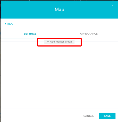
Click on the Add Marker Group.
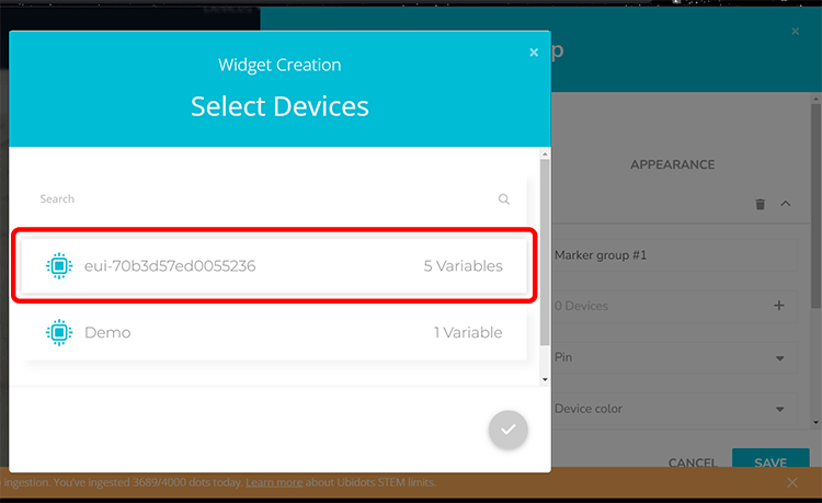
Select your LoRa Device.
Adjust the Map Trace settings according to your requirements and click on Save.
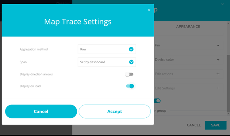
That’s it! All the position data received from the LoRa device will now be visible on the map Widget in the form of a location marker. You can also add other widgets like tables for displaying raw coordinate values and the SNR (Signal to Noise Ratio).
![]()
ESP8266 Lora GPS Tracker Working
The below image shows the actual hardware and how the lattitue and longitude value gets update on ubidots. Our Lora GPS tracker range actually depends on how much LoRa Gateway is present in the area. We will be able to send data to ubidots as long as there is a gateway within the reach of your LoRa module, in our case we had only one gateway set-up in our office (indoor) and we were able to cover only 2-3 km around the gateway.
![]()
#include <lmic.h>
#include <hal/hal.h>
#include <SPI.h>
#include <TinyGPSPlus.h>
TinyGPSPlus gps; String ProcData="Hello,World";
#ifdef COMPILE_REGRESSION_TEST
# define FILLMEIN 0
#else
# warning "You must replace the values marked FILLMEIN with real values from the TTN control panel!"
# define FILLMEIN (#dont edit this, edit the lines that use FILLMEIN)
#endif
// This EUI must be in little-endian format, so least-significant-byte
// first. When copying an EUI from ttnctl output, this means to reverse // the bytes. For TTN issued EUIs the last bytes should be 0xD5, 0xB3,
// 0x70. static const u1_t PROGMEM APPEUI[8]= {0x00, 0x00, 0x00, 0x00, 0x00, 0x00, 0x00, 0x00}; void os_getArtEui (u1_t* buf) { memcpy_P(buf, APPEUI, 8);}
// This should also be in little endian format, see above.
static const u1_t PROGMEM DEVEUI[8]= {0x36, 0x52, 0x05, 0xD0, 0x7E, 0xD5, 0xB3, 0x70};
void os_getDevEui (u1_t* buf) { memcpy_P(buf, DEVEUI, 8);}
// This key should be in big endian format (or, since it is not really a
// number but a block of memory, endianness does not really apply). In
// practice, a key taken from ttnctl can be copied as-is.
static const u1_t PROGMEM APPKEY[16] = {0x97, 0x7B, 0x4B, 0xA3, 0x9A, 0x8D, 0x33, 0x5E, 0x42, 0x13, 0x9C, 0x6B, 0xE9, 0xF9, 0x5E, 0xE1};
void os_getDevKey (u1_t* buf) { memcpy_P(buf, APPKEY, 16);}
uint8_t mydata[25] ;
static osjob_t sendjob;
// Schedule TX every this many seconds (might become longer due to duty
// cycle limitations). const unsigned TX_INTERVAL = 2;
// Pin mapping
const lmic_pinmap lmic_pins = {
.nss = 15,
.rxtx = LMIC_UNUSED_PIN,
.rst = 16,
.dio = {5, 4, LMIC_UNUSED_PIN},
};
void printHex2(unsigned v) {
v &= 0xff;
if (v < 16)
Serial1.print('0');
Serial1.print(v, HEX);
}
void onEvent (ev_t ev) {
Serial1.print(os_getTime());
Serial1.print(": ");
switch(ev) {
case EV_SCAN_TIMEOUT: Serial1.println(F("EV_SCAN_TIMEOUT"));
break;
case EV_BEACON_FOUND: Serial1.println(F("EV_BEACON_FOUND"));
break;
case EV_BEACON_MISSED: Serial1.println(F("EV_BEACON_MISSED"));
break;
case EV_BEACON_TRACKED: Serial1.println(F("EV_BEACON_TRACKED"));
break;
case EV_JOINING: Serial1.println(F("EV_JOINING"));
break;
case EV_JOINED: Serial1.println(F("EV_JOINED")); {
u4_t netid = 0; devaddr_t devaddr = 0;
u1_t nwkKey[16];
u1_t artKey[16];
LMIC_getSessionKeys(&netid, &devaddr, nwkKey, artKey);
Serial1.print("netid: ");
Serial1.println(netid, DEC);
Serial1.print("devaddr: ");
Serial1.println(devaddr, HEX);
Serial1.print("AppSKey: ");
for (size_t i=0; i<sizeof(artKey); ++i) {
if (i != 0) Serial1.print("-");
printHex2(artKey[i]);
}
Serial1.println("");
Serial1.print("NwkSKey: ");
for (size_t i=0; i<sizeof(nwkKey); ++i) {
if (i != 0) Serial1.print("-");
printHex2(nwkKey[i]);
}
Serial1.println(); }
// Disable link check validation (automatically enabled
// during join, but because slow data rates change max TX
// size, we don't use it in this example. LMIC_setLinkCheckMode(0); break;
/* || This event is defined but not used in the code. No || point in wasting codespace on it. || || case EV_RFU1: || Serial1.println(F("EV_RFU1")); || break; */
case EV_JOIN_FAILED: Serial1.println(F("EV_JOIN_FAILED"));
break;
case EV_REJOIN_FAILED: Serial1.println(F("EV_REJOIN_FAILED"));
break;
case EV_TXCOMPLETE: Serial1.println(F("EV_TXCOMPLETE (includes waiting for RX windows)"));
if (LMIC.txrxFlags & TXRX_ACK) Serial1.println(F("Received ack"));
if (LMIC.dataLen) {
Serial1.print(F("Received "));
Serial1.print(LMIC.dataLen); Serial1.println(F(" bytes of payload"));
}
// Schedule next transmission
os_setTimedCallback(&sendjob, os_getTime()+sec2osticks(TX_INTERVAL), do_send);
break;
case EV_LOST_TSYNC: Serial1.println(F("EV_LOST_TSYNC"));
break;
case EV_RESET: Serial1.println(F("EV_RESET"));
break;
case EV_RXCOMPLETE: // data received in ping slot Serial1.println(F("EV_RXCOMPLETE"));
break;
case EV_LINK_DEAD: Serial1.println(F("EV_LINK_DEAD"));
break;
case EV_LINK_ALIVE: Serial1.println(F("EV_LINK_ALIVE")); break;
/* || This event is defined but not used in the code. No || point in wasting codespace on it. || || case EV_SCAN_FOUND: || Serial1.println(F("EV_SCAN_FOUND")); || break; */
case EV_TXSTART: Serial1.println(F("EV_TXSTART"));
break;
case EV_TXCANCELED: Serial1.println(F("EV_TXCANCELED"));
break;
case EV_RXSTART: /* do not print anything -- it wrecks timing */
break;
case EV_JOIN_TXCOMPLETE: Serial1.println(F("EV_JOIN_TXCOMPLETE: no JoinAccept"));
break;
default: Serial1.print(F("Unknown event: "));
Serial1.println((unsigned) ev);
break;
}
}
void do_send(osjob_t* j){
// Check if there is not a current TX/RX job running
if (LMIC.opmode & OP_TXRXPEND) {
Serial1.println(F("OP_TXRXPEND, not sending"));
}
else {
// Prepare upstream data transmission at the next possible
time. unsigned long start = millis();
do {
while (Serial.available())
gps.encode(Serial.read());
}
while (millis() - start < 1000);
float flat=gps.location.lat();
float flon=gps.location.lng();
char charLat[20];
char charLong[20];
Serial1.print("Cords: ");
Serial1.print(flat); Serial1.print(" , ");
Serial1.println(flon);
dtostrf(flat, 10, 7, charLat);
dtostrf(flon, 10, 7, charLong);
sprintf((char *)mydata, "%s,%sX", charLat,charLong);
LMIC_setTxData2(1, mydata,25, 0);
Serial1.println(F("Packet queued"));
//int x=ProcData.length();
//ProcData.toCharArray((char *)mydata,sizeof(mydata));
}
// Next TX is scheduled after TX_COMPLETE event.
}
void setup() {
Serial1.begin(9600);
Serial1.println(F("Starting"));
Serial.begin(9600);
// LMIC init os_init();
// Reset the MAC state. Session and pending data transfers will be discarded. LMIC_reset(); LMIC_setClockError(MAX_CLOCK_ERROR * 1 / 100);
// Start job (sending automatically starts OTAA too) do_send(&sendjob);
}
void loop() {
os_runloop_once();
}


