


Nowadays, security is the utmost concern for us, whether it is related to our assets like vehicles, homes or our children. In this case, GPS tracker devices are very useful. They can be easily used to track the real-time position of the vehicles or assets in case of any emergency like theft, accidents, etc. They can also be kept with children to track their location.
Here we are building the same GPS tracking device to monitor the real-time location of the vehicle from anywhere. Here ThingSpeak IoT cloud will be used to store the history of locations from where the vehicle has traversed. We previously interfaced with GPS with NodeMCU ESP8266 and displayed the location coordinates on a webpage. Here in this IoT Vehicle Tracking System, we will also display a link on the webpage which will take the user to Google map showing the vehicle location.
Components Required
- ESP8266 NodeMCU - 1
- NE06M GPS Receiver - 1
- 16*2 LCD - 1
- 16*2 LCD I2C module - 1
- Breadboard
- Connectors
- Power supply
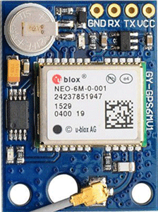
NEO6M GPS Module
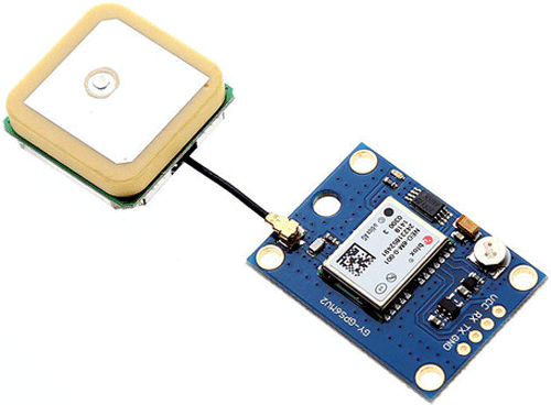
The NEO-6M GPS module is a popular GPS receiver with a built-in ceramic antenna, which provides a strong satellite search capability. This receiver has the ability to sense locations by tracking up to 22 satellites and identifies locations anywhere in the world. With the on-board signal indicator, we can monitor the network status of the module. It has a data backup battery so that the module can save the data when the main power is shut down accidentally.
The core heart inside the GPS receiver module is the NEO-6M GPS chip from u-blox. It can track up to 22 satellites on 50 channels and have a very impressive sensitivity level which is -161 dBm. This 50-channel u-blox 6 positioning engine boasts a Time-To-First-Fix (TTFF) of under 1 second. This module supports the baud rate from 4800-230400 bps and has the default baud of 9600.
Features:
- Operating voltage: (2.7-3.6)V DC
- Operating Current: 67 mA
- Baud rate: 4800-230400 bps (9600 Default)
- Communication Protocol: NEMA
- Interface: UART
- External antenna and built-in EEPROM.
Pinout of GPS module:
VCC: Input voltage pin of Module
GND: Ground pin
RX, TX: UART communication pins with Microcontroller
Vehicle Tracking System Circuit Diagram
Circuit diagram for this IOT based vehicle monitoring system is given below:
![]()
![]()
Setup ThingSpeak Account for IoT Vehicle Tracking System
After successful completion of hardware as per the above circuit diagram, now its time to set up the IoT platform, where the GPS coordinates are stored. Here we are using ThingSpeak to store the latitude and longitude data on the cloud and graphically visualize the GPS data.
ThingSpeak is a very popular IoT based cloud platform and we built many IoT based projects using ThingSpeak previously. Below are the steps for setting up the ThingSpeak cloud.
Step 1: Sign up for ThingSpeak
First, go to https://thingspeak.com/ and create a new free Mathworks account if you don’t have a Mathworks account before.
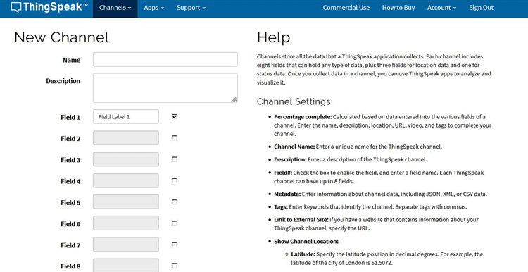
Step 2: Sign in to ThingSpeak
Sign in to ThingSpeak using your credentials and click on “New Channel”. Now fill up the details of the project like Name, Field names, etc. Here we have to create two field names such as Latitude and Longitude. Then click on “Save channel”.
Step 3: Record the Credentials
Select the created channel and record the following credentials.
- Channel ID, which is at the top of the channel view.
- Write an API key, which can be found on the API Keys tab of your channel view.

Programming NodeMCU for Vehicle Tracking System
After the successful completion of the Hardware connections and ThingSpeak setup, now it’s time to program the ESP8266 NodeMCU. The stepwise explanation of the complete code is given below.
To upload code into NodeMCU using Arduino IDE, follow the steps below:
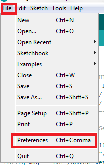
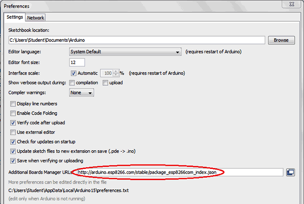
1. Open Arduino IDE, then go to File–>Preferences–>Settings.
2. Type https://arduino.esp8266.com/stable/package_esp8266com_index.json in the ‘Additional Board Manager URL’ field and click ‘Ok’.
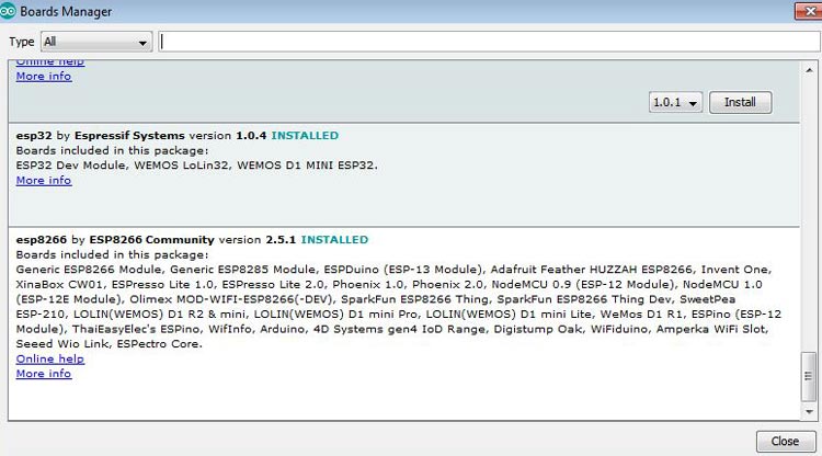
3. Now go to Tools > Board > Boards Manager. In the Boards Manager window, Type ESP8266 in the search box, select the latest version of the board and click on install.
4. After installation is complete, go to Tools ->Board -> and select NodeMCU 1.0(ESP-12E Module). Now you can program NodeMCU with Arduino IDE.
After setting up NodeMCU in Arduino IDE, upload the code into NodeMCU. Complete code is given at the end of this tutorial; here we are explaining the code step by step.
Start the code by including all the required library files in the code like ESP8266WiFi.h for ESP8266 board, LiquidCrystal_I2C.h for LCD, Wire.h for I2C communication, etc.
Here, ThingSpeak.h library is added to use the ThingSpeak platform with NodeMCU and TinyGPS++.h The library is used to get the GPS coordinates using the GPS receiver module. This library can be downloaded from here.
#include <TinyGPS++.h>
#include <SoftwareSerial.h>
#include "ThingSpeak.h"
#include <ESP8266WiFi.h>
#include<LiquidCrystal_I2C.h>
#include<Wire.h>
For using the I2C module for 16x2 Alphanumeric LCD, configure it using the LiquidCrystal_I2C class. Here we have to pass the address, row, and column number which are 0x27, 16, and 2 respectively in our case.
LiquidCrystal_I2C lcd(0x27, 16, 2);
Now, declare the network credentials- i.e. SSID and password. It is required to connect the NodeMCU to the internet.
const char* ssid     = "admin";
const char* password = "12345678";
Now, declare the connection pins of the GPS module and it’s the default baud rate, which is 9600 in our case.
static const int RX= D6, TX= D7;
static const uint32_t GPSBaud = 9600;
Next, declare the ThingSpeak account credentials such as the channel number and write API which was recorded earlier.
unsigned long ch_no = 9XXXX;
const char * write_api = "ZWWWDXXXXXXXXX";
Then declare the objects for TinyGPSPlus and WiFiClient class. For using WiFiServer properties, the server object is defined with Port number 80.
TinyGPSPlus gps;
WiFiClient  client;
WiFiServer server(80);
SoftwareSerial soft(RX, TX);
Inside setup(), declare all the input pins and output pins. Then print a welcome message on the LCD which will be displayed during the initialization of the project.
  Wire.begin(D2, D1);
  lcd.begin(16, 2);
  lcd.init();
  lcd.backlight();
  lcd.setCursor(0, 0);
  lcd.print("   IOT BASED       ");
  lcd.setCursor(0, 1);
  lcd.print("VEHICLE TRACKING   ");
  delay(2000);
  lcd.clear();
To connect NodeMCU to the internet, call WiFi.begin and pass network SSID and password as its arguments. Check for the successful network connection using WiFi.status() and after a successful connection, print a message on LCD with IP address.
  WiFi.begin(ssid, password);
  server.begin();
  while (WiFi.status() != WL_CONNECTED)
  {
    delay(500);
    lcd.setCursor(0, 0);
    lcd.print("WiFi connecting...          ");
  }
  lcd.setCursor(0, 0);
  lcd.print("WiFi connected          ");
  lcd.setCursor(0, 1);
  lcd.print(WiFi.localIP());
Then connect to the ThingSpeak platform, using saved credentials. For this ThingSpeak.begin is used.
ThingSpeak.begin(client);
Inside loop(), encode () is used to ensure a valid GPS sentence is received. When encode () returns “true”, a valid sentence has just changed the TinyGPS object’s internal state. Here two functions namely displaydata() and displaywebpage() are called, when encode() returns true.
while (soft.available() > 0)
    if (gps.encode(soft.read()))
    {
      displaydata();
      displaywebpage();
    }
  if (millis() > 5000 && gps.charsProcessed() < 10)
  {
    Serial.println(F("GPS Connection Error!!"));
    while (true);
  }
Inside displaydata() function, isValid() method is used to ensure a valid latitude and longitude reception and they are stored in respective variables. Then to send these data to ThingSpeak, setField() method is used to set the fields and the writeFields() method is used to send these data to the cloud.
void displaydata()
{
  if (gps.location.isValid())
  {
    double latitude = (gps.location.lat());
    double longitude = (gps.location.lng());
    latitude_data= (String(latitude, 6));
    longitude_data= (String(longitude, 6));
    ThingSpeak.setField(1, latitude_data);
    ThingSpeak.setField(2, longitude_data);
    ThingSpeak.writeFields(ch_no, write_api);
    delay(20000);
  }
  else
  {
    Serial.println(F("Data error!!!"));
  }
}
Inside displaywebpage(), a HTML code is written which is sent to Client-side in string format using client.print(). This HTML code contains a hyperlink which on clicking, takes you to the Google maps pointing the location of a tracked vehicle.
{
    WiFiClient client = server.available();
    if (!client)
    {
      return;
    }
    String page = "<html><center><p><h1>Real Time Vehicle Tracking using IoT</h1><a style=""color:RED;font-size:125%;"" href=""http://maps.google.com/maps?&z=15&mrt=yp&t=k&q=";
    page += latitude_data;
    page += "+";
    page += longitude_data;
    page += ">Click here For Live Location</a> </p></center></html>";
    client.print(page);
    delay(100);
}
![]()
Testing of Vehicle Monitoring System using IoT
After connecting the hardware and uploading the code, just power on the circuit and you will see some notifications messages on LCD. Now open the web browser and open type the IP address of the NodeMCU. There will be a link that will take you to the google map with the current location of the vehicle as shown in the above pictures. The IP address of NodeMCU is displayed on LCD after Wi-Fi is connected successfully. Complete working is demonstrated in the video given below.
At the same time ThingSpeak will also log the Latitude and Longitude of the vehicle and present them in the graphs as shown below:
![]()
Complete code and video for this Vehicle Tracking System using IoT are given below.
#include <TinyGPS++.h>
#include <SoftwareSerial.h>
#include "ThingSpeak.h"
#include <ESP8266WiFi.h>
#include<LiquidCrystal_I2C.h>
#include<Wire.h>
LiquidCrystal_I2C lcd(0x27, 16, 2);
static const int RX= D6, TX= D7;
static const uint32_t GPSBaud = 9600;
const char* ssid = "admin";//Replace with Network SSID
const char* password = "12345678";//Replace with Network Password
unsigned long ch_no = 12345;//Replace with Thingspeak Channel number
const char * write_api = "ZS6XXXXXXXXXXXX";//Replace with Thingspeak write API
TinyGPSPlus gps;
WiFiClient client;
WiFiServer server(80);
SoftwareSerial soft(RX, TX);
String latitude_data;
String longitude_data;
void setup()
{
Wire.begin(D2, D1);
lcd.begin(16, 2);
lcd.init();
lcd.backlight();
lcd.setCursor(0, 0);
lcd.print(" IOT BASED ");
lcd.setCursor(0, 1);
lcd.print("VEHICLE TRACKING ");
delay(2000);
lcd.clear();
Serial.begin(115200);
soft.begin(GPSBaud);
WiFi.begin(ssid, password);
server.begin();
while (WiFi.status() != WL_CONNECTED)
{
delay(500);
lcd.setCursor(0, 0);
lcd.print("WiFi connecting... ");
}
lcd.setCursor(0, 0);
lcd.print("WiFi connected ");
lcd.setCursor(0, 1);
lcd.print(WiFi.localIP());
ThingSpeak.begin(client);
}
void loop()
{
while (soft.available() > 0)
if (gps.encode(soft.read()))
{
displaydata();
displaywebpage();
}
if (millis() > 5000 && gps.charsProcessed() < 10)
{
Serial.println(F("GPS Connection Error!!"));
while (true);
}
}
void displaydata()
{
if (gps.location.isValid())
{
double latitude = (gps.location.lat());
double longitude = (gps.location.lng());
latitude_data= (String(latitude, 6));
longitude_data= (String(longitude, 6));
ThingSpeak.setField(1, latitude_data);
ThingSpeak.setField(2, longitude_data);
ThingSpeak.writeFields(ch_no, write_api);
delay(20000);
}
else
{
Serial.println(F("Data error!!!"));
}
}
void displaywebpage()
{
WiFiClient client = server.available();
if (!client)
{
return;
}
String page = "<html><center><p><h1>Real Time Vehicle Tracking using IoT</h1><a style=""color:RED;font-size:125%;"" href=""http://maps.google.com/maps?&z=15&mrt=yp&t=k&q=";
page += latitude_data;
page += "+";
page += longitude_data;
page += ">Click here For Live Location</a> </p></center></html>";
client.print(page);
delay(100);
}


