


Zigbee is a popular wireless communication protocol used to transfer a small amount of data with very low power. It is widely used in applications where data has to be shared among many nodes within personal space, and with the advent of the Internet of things (IoT), the application for Zigbee is fast growing. It is used in home automation, asset tracking, remote data collection, and much more. If you are already familiar with the architecture of Zigbee and Zigbee protocols, then you already know that wireless communication between two XBee modules can be done without any additional microcontrollers, but in practical application, these modules will always be interfaced with a microcontroller to read and send data. Let’s take that a step further and learn how to establish Zigbee communication using Arduino and NodeMCU boards.
Difference between Zigbee and XBee
It is important to clarify at the beginning itself that XBee is a module, a product, which supports many wireless communication protocols like ZigBee, Wi-Fi (Wi-Fly module), 802.15.4, 868 MHz modules, etc. Whereas, Zigbee is a standard protocol used to establish wireless networking (ZigBee communication). Often people use these two terms interchangeably but it shouldn’t be done so. To establish Zigbee communication, we need a receiver (endpoint). For this, an XBee module connected with Arduino/NodeMCU will do, and this will communicate wirelessly with another XBee module (coordinator) that sends data, will be connected to another Arduino board.
Hardware Requirements for Establishing Zigbee Communication
- 1 x Arduino Nano
- 1 x NodeMCU
- 2 x XBee Pro S2C modules
- 1 x XBee explorer board (to program XBee)
- USB cables
- LED (along with a 220-ohm resistor)
- Push Button
Configuring XBee Modules using XCTU Software
Basically, the XBee module can be configured as Coordinator, Router, or End device. To make it work as we desire, first, we have to configure them using XCTU software. You can download and install the XCTU software using the given link.
Use USB to serial converter or an explorer board to connect the XBee module with a PC or Laptop. Connect the XBee module to the Explorer board and plugin using a USB cable. We will get into the details on how exactly we can use this software and configure the module, but before we do that, let's get our hardware ready.
Interfacing XBee with Arduino (Transmitting Side)
For this side of the connection, we’ve used Arduino Nano. Arduino Uno or NodeMCU boards could also be used. The complete circuit diagram to interface XBee with Arduino nano is shown below.
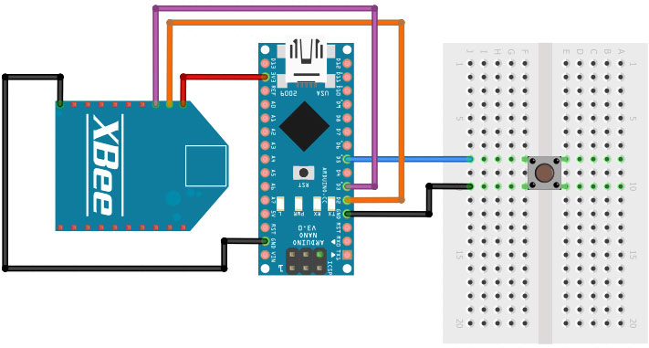
In the above Arduino XBee circuit diagram, we have used a push-button which, when pressed, will transmit data. For this, connect one end of the button to D5 of Arduino and the other end of the button to GND.
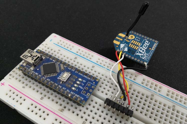
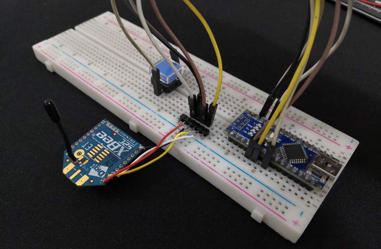
Connect VCC (pin 1) of XBee module to 3.3V of Arduino Nano and GND (pin 10) of XBee to GND of Arduino Nano. These two connections make up for powering the transmitting side XBee module. Connect Dout (pin 2) to D2 of Arduino Nano and Din (pin 3) to D3 of Arduino Nano. I used a breadboard to build this circuit and my hardware set-up with all the connections is shown below.
Interfacing XBee with NodeMCU (Receiving side)
For this, we’ve used NodeMCU, but it has certain constraints. You can also use Arduino Nano or Arduino Uno for the purpose. The idea of using an Arduino to transmit data and NodeMCU to receive data is that it will have a more practical application like the Arduino can collect some sensor parameters and send it to the NodeMCU via ZigBee, then NodeMCU can process this data and share it or take any action via the Internet as required. The complete circuit diagram to interface XBee with NodeMCU is shown below.
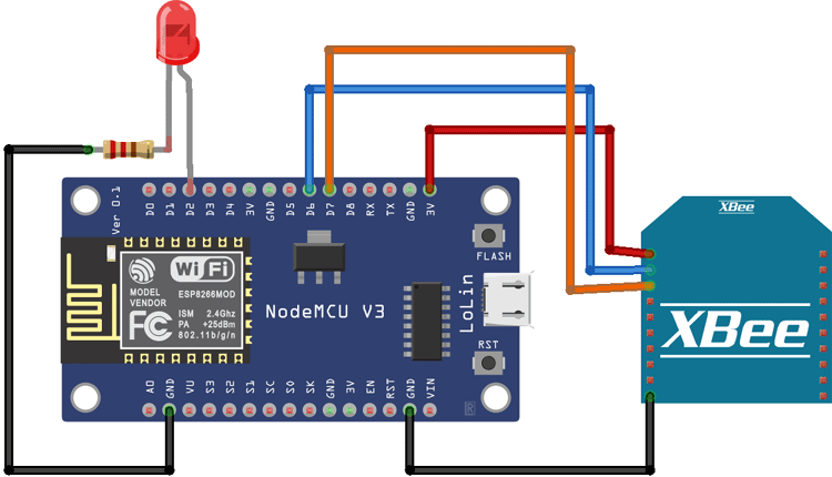
Connect Gnd(pin10) of XBee to GND of NodeMCU and Connect Vcc (Pin1) of XBee to 3.3V of NodeMCU. The above-mentioned two connections supply the power to the XBee module as well. Then connect Dout (pin2) of XBee to D6 pin of NodeMCU and Din (pin3) of XBee to D7 pin of NodeMCU for receiving data.
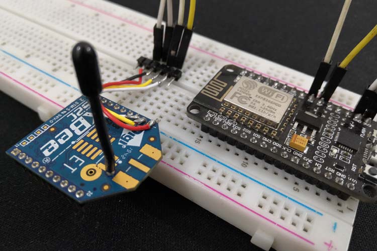
As an indication of whether the data is received or not, we’ve used LED. For this, connect LED anode to D2 of NodeMCU and LED cathode to GND through a 220ohm resistor of NodeMCU. Again, I used a breadboard to build this circuit and my hardware set-up with all the connections is shown below.
Downloading and Installing XCTU Software
To set up, configure and test your XBee devices. You need XCTU software. It’s an easy-to-use, free, multi-platform application for RF XBee modules. Download the XCTU software here and it’ll guide you to install it as well. After that, open the application and make sure your XBee module is connected properly. Check the COM port of the explorer board in the device manager.
Installing Firmware to XBee Modules
Firmware should be installed in both the XBee modules first, for that we’re using the XBee development board.
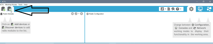
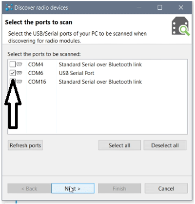
Step 1: Open XCTU software and click on “Discover boards”.
Step 2: Select the COM port to which the XBee module is connected and click on “Next”.
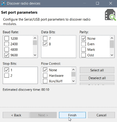
Step 3: Keep the default settings and click on “Finish”.
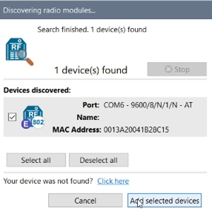
Step 4: Now, on the pop-up window, click on “Add Selected Devices”.
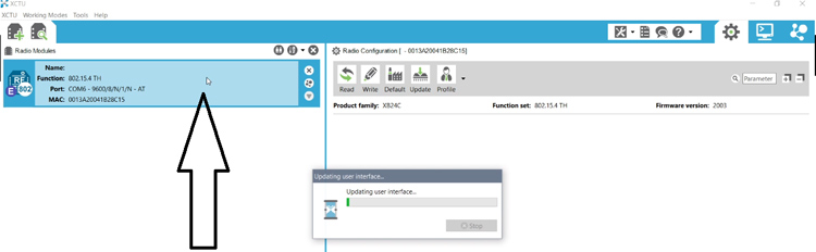
Step 5: Now, the XBee module will appear on the left side of the window. Click on it to update the user interface.
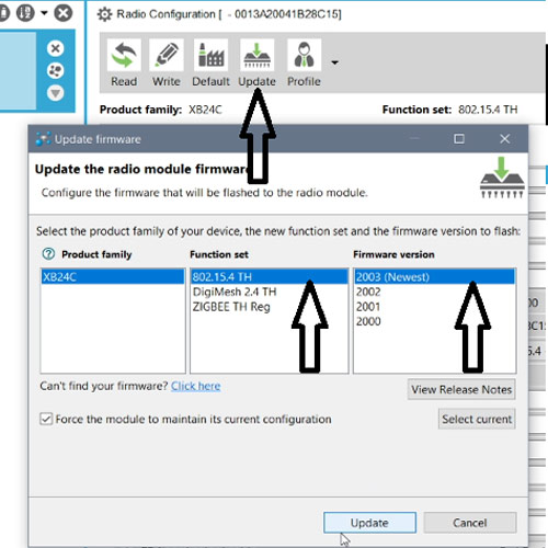
Step 6: To update the firmware, click on “Update”, select “802.15.4 TH” in the Function set and select the newest firmware in the Firmware version and click on update. After this, a pop-up window will appear. Click on YES.
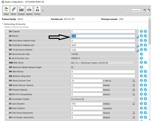
Step 7: Enter any 4 digits as PAN ID. PAN ID is a personal area network (PANs) identifier. Each network must be given a unique ID. Make sure that for both the XBee modules, the same PAN ID is entered. This indicates that both the XBee modules are in the same network.
Step 8: Give any 4 digits for the Destination Address. This same number must be entered as Source Address for the other XBee module.
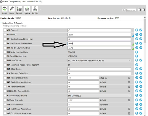
Step 9: Give any 4 digits for the Source Address. This same number must be entered as the Destination Address for the other XBee module.
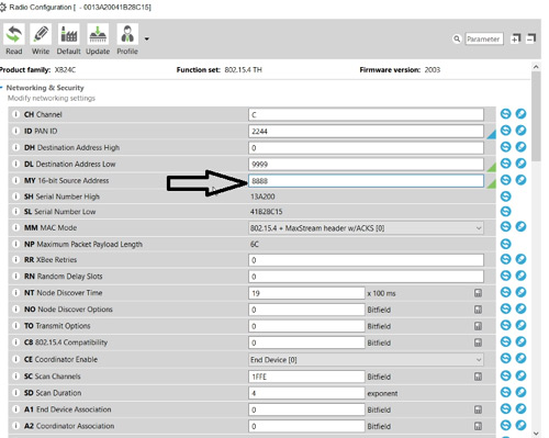
Step 10: Set one device as “Coordinate [1]” and the other device as “End Device [0]”.
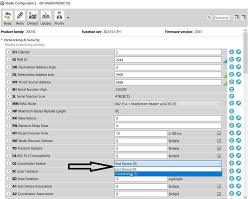
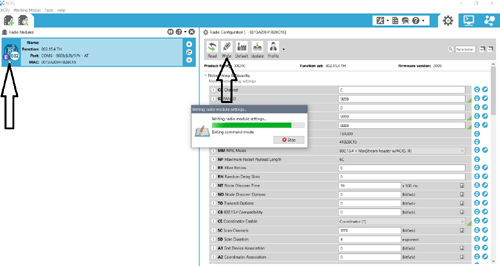
Step 11: Now, click on Write in the top bar. After that is successful, the Symbol changes from “E” to “C” (End Device to Coordinator, as we have set. For the other XBee module, it should be “E”).
Note: As mentioned in the steps, this must be carried out for both the XBee modules. The only difference between both will be that the Source and Destination Addresses are opposite for the End Device and Coordinator and one must be selected as the End Device and the other as “Coordinator”. In the “Coordinator Enable” drop-down list, make sure both the XBee modules are given the same PAN ID.
COM 5 is for nodeMCU (receiving side) and COM 14 is for Arduino nano (Sending side).
|
|
Destination Address |
Source Address |
PAN ID |
|
XBee module 1 (Coordinator) |
9999 |
8888 |
9898 |
|
XBee module 2 (End Device) |
8888 |
9999 |
9898 |
Soldering XBee Pins to Arduino and NodeMCU
The pins of the XBee module are not compatible with breadboards. Hence, solder 4 wires from XBee module pins to header pins and use that to connect to the breadboard as shown in the figure below. Alternatively, you can also use female to male header connector wires, if you want to avoid soldering works.
In an overview, two XBee modules are used to establish ZigBee communication. An Arduino Nano and NodeMCU is used to communicate between both the XBee devices. The XBee modules are coded such that when a push-button is pressed on the Transmitter side, LED is lit on the Receiving side. This indicates that the data transmitted at the source is received properly at the destination.
ZigBee Communication Program for Arduino
The complete Arduino code for Zigbee communication can be found at the bottom of this page. The explanation of the code is as follows.
#include "SoftwareSerial.h"
SoftwareSerial XBee(2,3);
This part emulates serial communication in pin 2 (Rx) and pin 3 (Tx)
int BUTTON = 5;
Pin 5 is where the button is connected on Arduino Nano, this is needed for sending the information.
boolean toggle = false;
To track if the button is clicked or not, the statement is used. If the button is pressed once, it turns the LED ON, if it is pressed again, it turns the LED OFF. To keep track of this, the toggle is used.
void setup()
{
  Serial.begin(9600);
The program starts from a void setup, and the baud rate for the serial monitor is set.
pinMode(BUTTON, INPUT_PULLUP);
Initializing the button pin to read input.
  XBee.begin(9600);
}
This part of the snippet uses software serial to begin the connection between XBee and Arduino. 9600 is the default communication speed for the XBee module.
void loop()
{
   if (digitalRead(BUTTON) == LOW && toggle)
   {
This part is to check if the button is pressed. If it is pressed, then the pin reads LOW and makes a note of this. It also checks if the button is previously clicked.
Serial.println("Turn on LED");
This part is to print the message on the serial monitor
toggle = false;
Reset the previous click so that it can detect the click again. When the toggle is false, this puts the LED in an OFF state.
XBee.write('1');
Send the message to XBee
delay(1000);
}
A delay of 1 second is caused to wait for the message to be delivered
else if (digitalRead(BUTTON) == LOW && !toggle)
{
This bit checks if the button is clicked
Serial.println("Turn off LED");
Print the message on the serial monitor
toggle = true;
Set to the previous clicked state to turn OFF the LED
XBee.write('0');
Send the message to XBee
delay(1000);
   }
}
Create one-second delay to wait for the message to be delivered
ZigBee Communication Program for NodeMCU
The complete NodeMCU code for Zigbee communication can be found at the bottom of this page. The explanation of the code is as follows.
#include<SoftwareSerial.h>
The Receiver part of the code is almost the same as Arduino code
SoftwareSerial zigbee(13,12);
This part emulates serial communication in pin 13 (Rx) and pin 12 (Tx)
int led = 2;
Set LED as pin 2
int received = 0;
To store the received data from XBee
void setup() {
  Serial.begin(9600);
  zigbee.begin(9600);
Initialize serial monitor and connect to XBee module with default baud rate i.e 9600
pinMode(led, OUTPUT);
}
Initialize the LED as output
void loop() {
  if (zigbee.available() > 0) {
Check if any data is available from XBee
received = zigbee.read();
Store the data in the received variable
if (received == '0'){
Check if the received data is 0
    Serial.println("Turning off LED");
    digitalWrite(led, LOW);
    }
Then print the message and turn OFF the LED
   else if (received == '1'){
    Serial.println("Turning on LED");
    digitalWrite(led, HIGH);
  }
}
}
If the received data is 1, then print the message and turn ON the LED.
I hope you liked the tutorial, if you have any questions regarding this project, please comment down below. Also, check out the working demonstration of this project given below.
CODE: Receiver side
#include<SoftwareSerial.h>
int led = 2;
int received = 0;
int i;
SoftwareSerial zigbee(13,12);
void setup() {
Serial.begin(9600);
zigbee.begin(9600);
pinMode(led, OUTPUT);
}
void loop() {
if (zigbee.available() > 0) {
received = zigbee.read();
if (received == '0'){
Serial.println("Turning off LED");
digitalWrite(led, LOW);
}
else if (received == '1'){
Serial.println("Turning on LED");
digitalWrite(led, HIGH);
}
}
}
CODE: Transmitter side
#include "SoftwareSerial.h"
SoftwareSerial XBee(2,3);
int BUTTON = 5;
boolean toggle = false;
void setup()
{
Serial.begin(9600);
pinMode(BUTTON, INPUT_PULLUP);
XBee.begin(9600);
}
void loop()
{
if (digitalRead(BUTTON) == LOW && toggle)
{
Serial.println("Turn on LED");
toggle = false;
XBee.write('1');
delay(1000);
}
else if (digitalRead(BUTTON) == LOW && !toggle)
{
Serial.println("Turn off LED");
toggle = true;
XBee.write('0');
delay(1000);
}
}


