


Inventory control is the key component in effective store management. Keeping track of your stocks leads to proper pre-planning and decision-making. Nowadays, our local supermarkets and large factories store their goods on big shelves or in huge storage rooms, and to know the current quantity of store/business, owners have to manually count the packets. This process not only takes time but also introduces man-made errors. In the case of large storerooms, the situation becomes quite complex, and it becomes very difficult for humans to manually check the inventory on a regular basis.
This is why in this tutorial, we thought of building an Internet of Things and sensors based Automated Inventory management system with the help of the popular NodeMCU ESP8266 microcontroller, which can automatically detect the number of goods present on a shelf or, can accurately provide the weight of a particular good. And to make it convenient, we will incorporate IoT technology with the ThingSpeak cloud platform so that the store owner can monitor the inventory from his home/office. And finally, we will use another popular technology, IFTTT to send an email if a product quantity goes below a certain level. So without further ado, let's get started.
We have previously used ThingSpeak with ESP8266 to build Air Quality Monitor system, IoT weather station, and Smart Street light. You can check all the ThingSpeak and ESP2866 related projects by following the respective links.
Automatic Inventory Management System - Working
To know the number of packets available in the inventory, we have to know the total weight and the weight of an individual packet. For example, if the weight of 1 package is 10 grams and the total weight of the shelf for inventory is 100 grams, then we can easily calculate the number of packets available on the shelf by dividing the total weight by the weight of one individual pack. In the mentioned example, we will get 10 packs. So, the next question is, how to calculate or how to measure the total weight. The answer to that question is simple, we will use a load cell. We can measure the total weight, and we can do all the necessary calculations with the help of a microcontroller. This way, we can calculate the number of packages available in the inventory.
Now, let's upload this value to a cloud platform so that we can monitor the status of our inventory management system from anywhere in the world with the help of our inventory management software. In our project, we are going to use a NodeMCU and ThingSpeak to do all the work.
Components Required to Build the Automated Inventory Management System
All the hardware components used to build this project are very generic, and you can find most of those in your local hobby store. A list of required components is given below.
- NodeMCU - 1
- Load Cell - 1
- HX711 Load Cell Amplifier Module
- 128*64 OLED Display
- Connecting Wires
- MDF, Cardboard, Foam Sheet - for Encloser
- 7.4-volt li-ion Battery
Component Description of Automatic Inventory Management System
Before proceeding further in the article, we should know some details about the components used. In this section, we have discussed all the components that will be used to build the circuit.
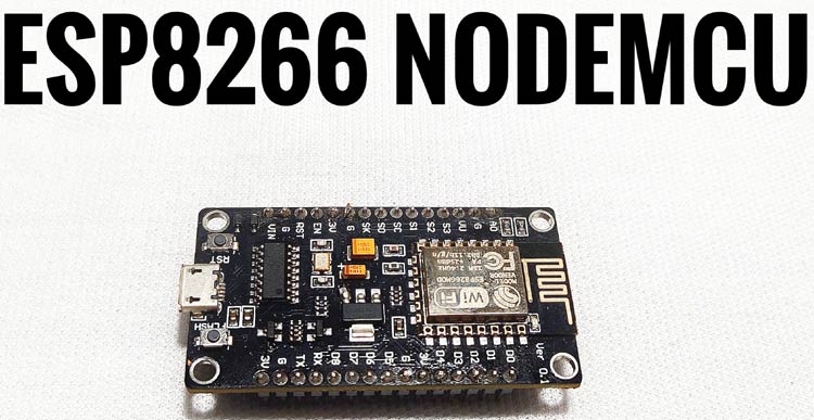
The NodeMCU ESP8266 Development Board:
NodeMCU is an open-source development platform that runs on the ESP8266 Wi-Fi SoC, which is developed by Espressif Systems. It has a built-in Wi-Fi module, which makes it suitable for IoT-related applications. That's why we are using NodeMCU. In our previous tutorials, we have used NodeMCU to build many other projects. You can check those out if you want to know about cooler NodeMCU based projects. An image of the NodeMCU board is shown below.
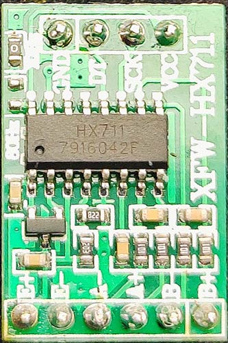
Load Cell and the HX711 Load Cell Amplifier Module:
The key component of this project is the load cell. This is our load cell as you can see, one side is marked with ten kilograms. You probably already noticed some sort of white protective glue over the load cell and four different wires of different colors are coming out, we will later see what is below in this white protective glue. First of all, these load cells are made of aluminum blocks and as you can see, the middle part of the material is thinner so that will be the point that will suffer deformation. A load cell has two sides, let's say right and left. Imagine that the cell is holding on the right side and the force is applied on the left side so that could bend the load cell. So, a small deformation will be created both on the top side and on the bottom side of the load cell. The top part will suffer tension and the bottom part will suffer compression. The aluminum bar is bending downwards on the left side. If we can measure this deformation, we could later measure the force that was applied to the aluminum block, and that's exactly what we will do.
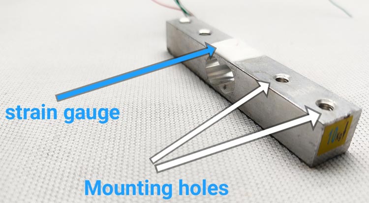
A strain gauge is a component that is used to measure strain. If we take a closer look at this component, we can see two connection pads, and then we have the conductive wire pattern with repetitive deflections. This conductive wire has a defined resistance. When we bend it, will the resistance value change? One side of the strain gauge is mounted and fixed in a place. If we place a weight on the other side of the aluminum bar, this will force the strain gauge to bend, which will cause a change in resistance. How does this happen? The conductive pattern of the strain gauge is made of copper, this wire will have a certain area and length, so these two units will give the resistance of the wire. The resistance of a wire opposes the flow of current.
Now, it's obvious that if the area of this wire gets smaller, fewer electrons could pass meaning a lower current. Now, if we increase the area, it will increase the resistance of a conductor. If some force is applied to this wire, this will stretch the area and it will get smaller and at the same time, resistance increases. But this resistance variation is very low. If we stretch the strain gauge, the resistance will increase and if we compress it, the resistance will get lower. To measure the force, we need to measure the resistance. Measuring the resistance directly is not always practical, because the change is very small. So, instead of measuring resistance, we can measure voltages easily. In this case, we need to convert the gauge output from resistance values to voltage values.
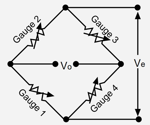
We can do this with the help of the Wheatstone bridge. We place the strain gauge in the Wheatstone bridge. If the bridge is balanced, the voltage in the middle point should be zero (previously we have built a project where we have described how a Wheatstone bridge works, you can check that out if you want to know more about the topic). When the strain gauge changes its resistance, it will unbalance the bridge, and the voltage will also change. So, this is how the Wheatstone bridge converts resistance variations to voltage values.
The 128X64 OLED Display:
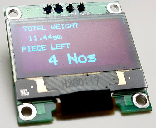
This organic light-emitting diode (OLED) display is a mono-color, 0.96-inch display with 128×64 pixels. As the name suggests, an OLED display does not require a backlight because they are LEDs in the display, which is why the display has a nice contrast in dark environments. Additionally, the pixels of this display is made out of LEDs so they consume a little energy only when they are on, the OLED display consumes less power when compared with other displays. It has only four pins and communicates with the microcontroller using an I2C communication protocol. OLED displays are perfect for battery-operated projects that's why we have used OLED here.
Automatic Inventory Management System Circuit Diagram
The complete circuit diagram for the IoT Based Automated Inventory Management System is shown below.
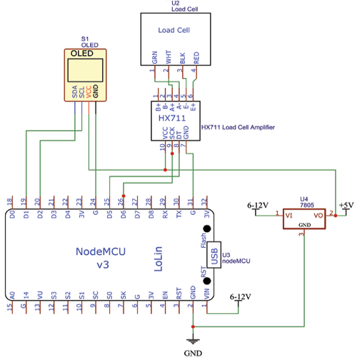
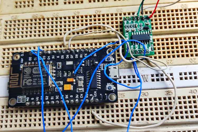
The circuit diagram of inventory is very simple. Here, we connected the OLED display to the I2C pins of NodeMCU, which are the D1 and D2 pins on the board. Next, we connect the loadcell to NodeMCU. Loadcell has four wires - Red, Black, Green, and White. The color may vary according to the manufacturers, so it's better to refer to the datasheet. Connect red to E+ of HX711 board, connect black to E-, connect white to A+, and connect green to A-, Dout, and clock of the board connect to D5 and D6, respectively. Then connect the grounds of the OLED display and amplifier to the ground of NodeMCU. OLED and the load cell amplifier work on 5v, but the NodeMCU doesn't have 5v pins so we have to use a 5v regulator with the circuit. The image given below shows the breadboard prototype.
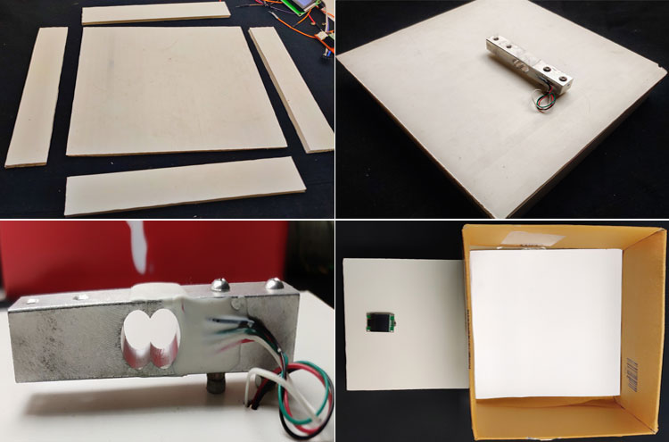
Automatic Inventory Management System - Encloser to House the Circuitry
To hold the circuitry and the inventory, we need to make an encloser. For that, we are using a PVC sheet. You can use any type of materials like MDF, Foam Sheet, etc. Here, I am using a PVC sheet for better strength. First, I cut 20 x 20cm square and three 20 x 5 rectangles from the PVC board. Then, using hot glue and the cut-down pieces of the PVC, I made a small box. Then I used an old cardboard box as a top (storage space) of the scale. You must leave some space from the ground to the cell so it will be able to bend. Place screw nuts in between the load cell and the base. I added plastic spacers in between the loadcell and top part. This is how I made the inventory body. You can design with your ideas, but remember to place the load cell as shown in the image. You can use the images given below as a reference.
Setting-Up ThingSpeak Account for Automatic Inventory Management System
ThingSpeak is an open data IoT Analytics platform that allows you to aggregate, visualize, and analyze live data in the cloud. You can control your devices using ThingSpeak, you can send data to ThingSpeak from your devices, and you can even create instant visualizations of live data, and send alerts using web services like Twitter and ThingHTTP.
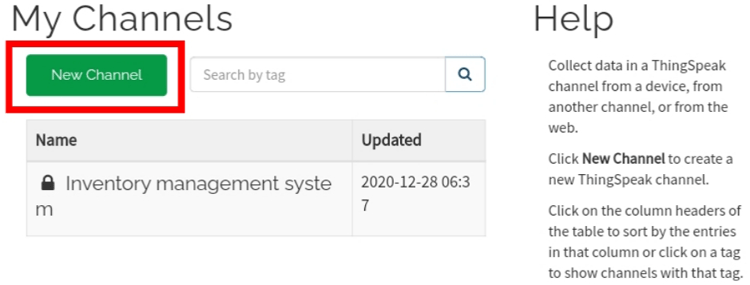
First, go to Thingspeak.com and signup with your mail, then click on channels. From there, click on the new channel to create the interface.

Now, you will see a tab like this for creating the channel, give name and Description (if you want). We need two fields to collect the data from esp (total weight and nom of pieces left). For that, give the name ‘total weight’ and ‘number of pieces left’ in Field 1 and Field 2. Tick the checkboxes for both Fields. Also, tick the check box for the ‘Make Public’ option below in the form and finally Save the Channel. Now, your new channel has been created.
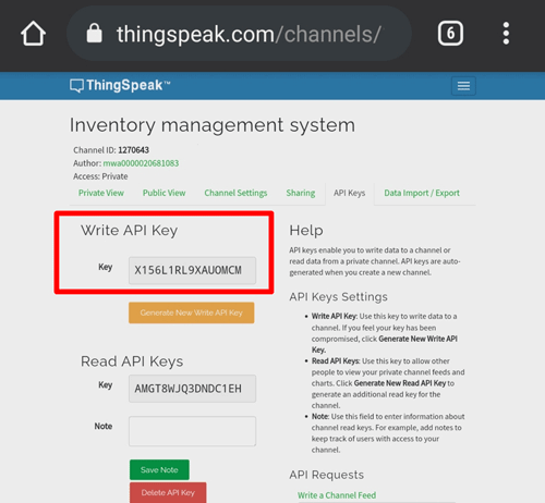
After that, click on API keys and copy the write API key. We need to enter this key in the main program to upload data to the ThingSpeak cloud.
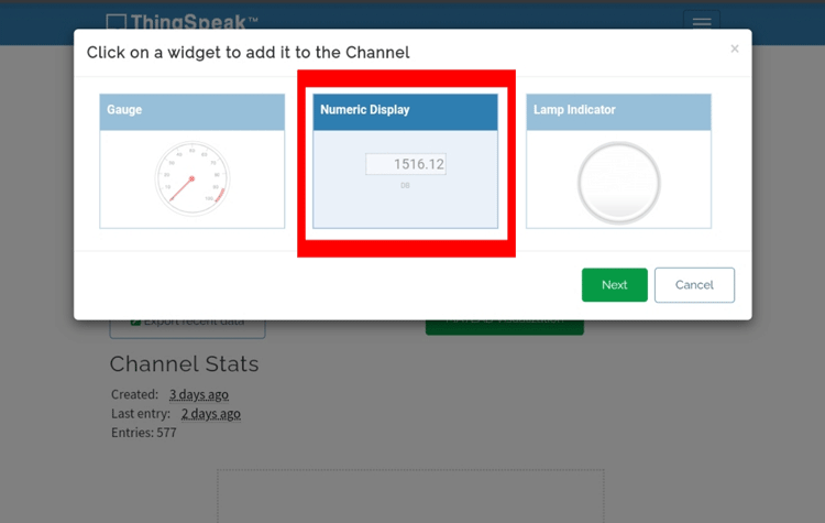
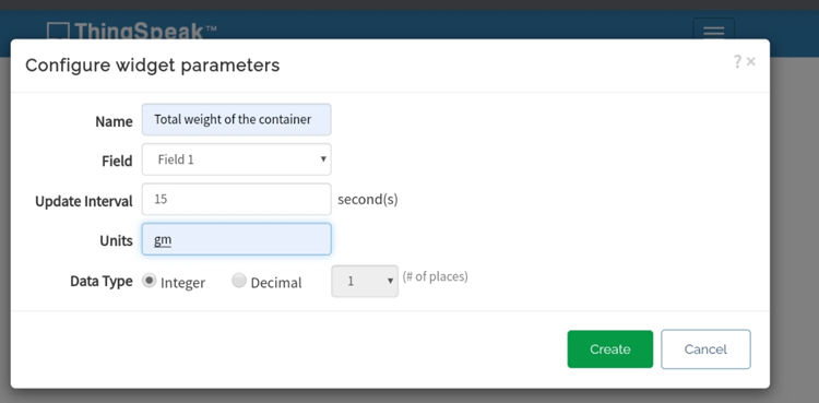
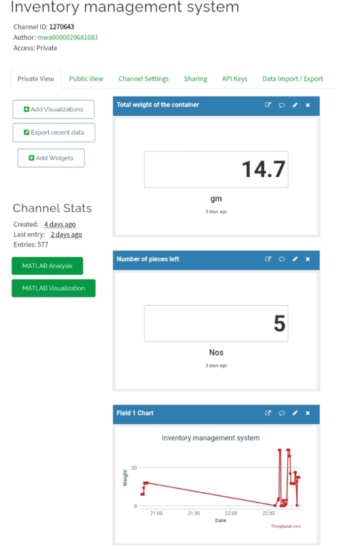
Now, we need to display the data on the website. For that, click on the widget and select a widget. Here, we need to display the total weight and piece number (numeric) so select numeric display and click next. Now, we need to name the widget. Here, I am writing "total weight of the container". Now, select field 1(because we need to display the value of field one). Then select the unit and click create. Do the same for the second field.
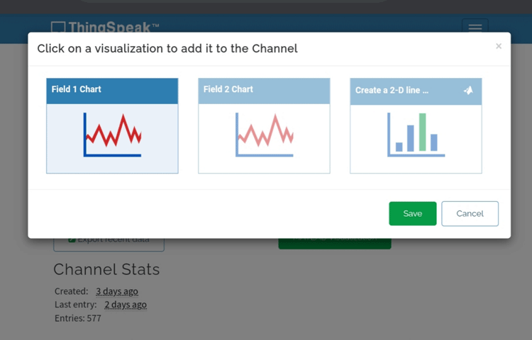
Next, click on add visualization and add a chart for displaying the quantity graphically (if you want). Now, our interface is ready to receive data and looks something like this.
IFTTT Setup for Automatic Email Notification
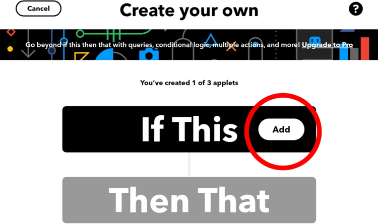
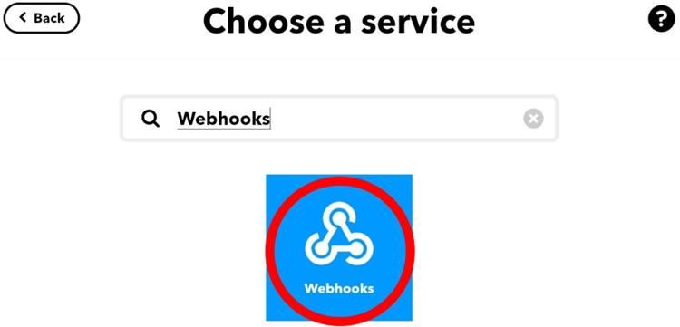
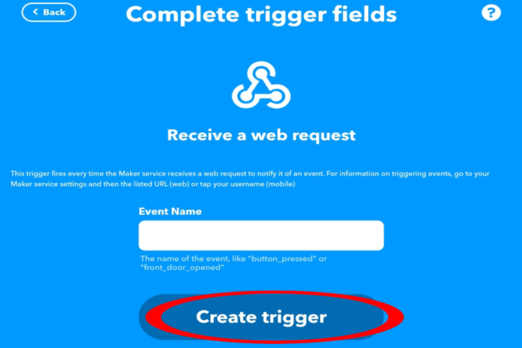
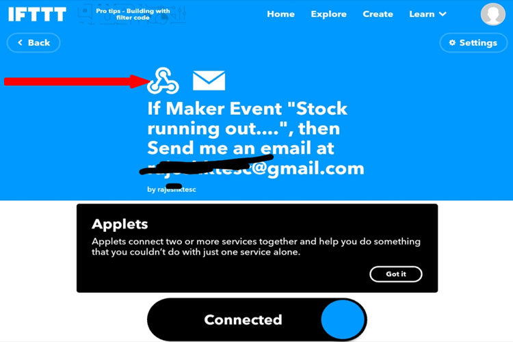
In the introduction section, we told you that we will send an email whenever a certain threshold is reached. For that, we need to set up an IFTTT account. For that, first, go to ifttt.com and sign up / sign in with your credentials. Click on the add button located near this search webhooks and select webhooks, give an event name, and create the trigger. Now, you can see the webhooks logo after it.
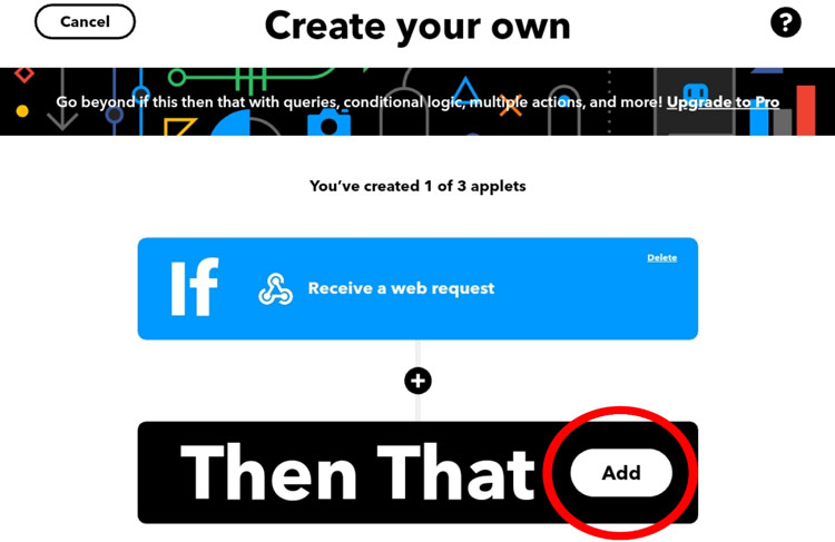
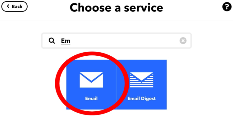
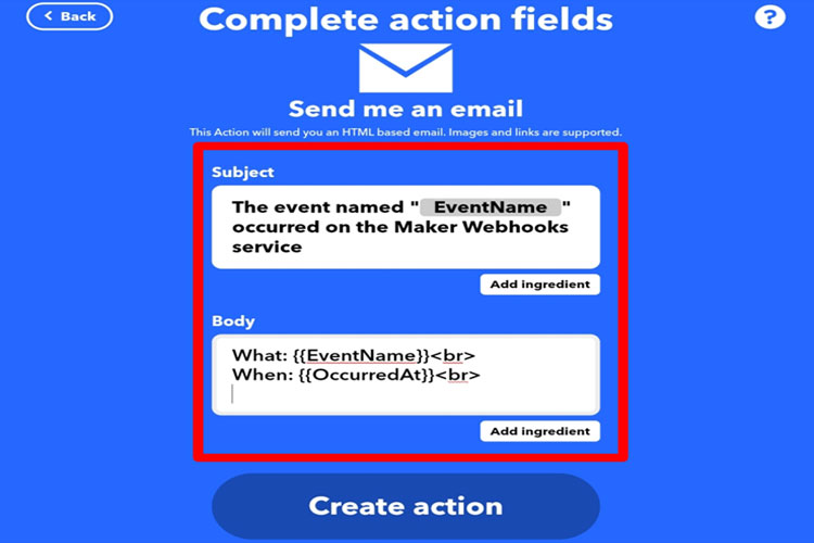
Now, click on the next to add button and search for “email” and select the email to customize your message according to your wish. Also, customize the body of the mail. Here, I wrote "stock running out" and click finish. Here, the “This” function will be for webhooks service and the “that” function will be email Services.
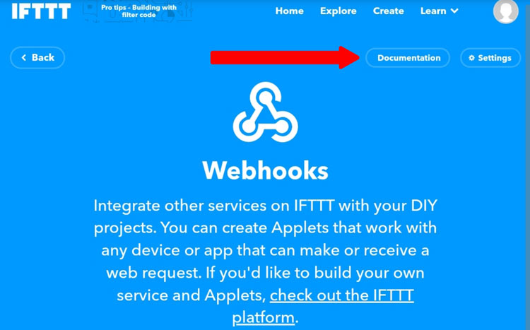
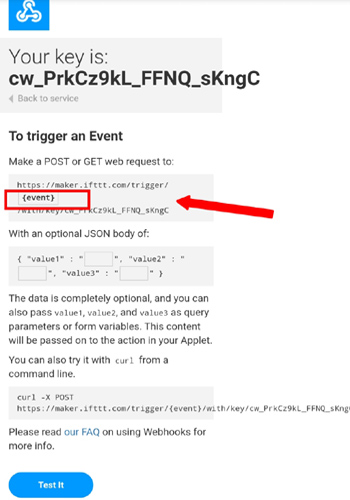
Now, click on the webhooks logo and then click on the documentation. Then we need to change the event name. Replace the event exactly with our event name. After that, copy the URL that is shown.
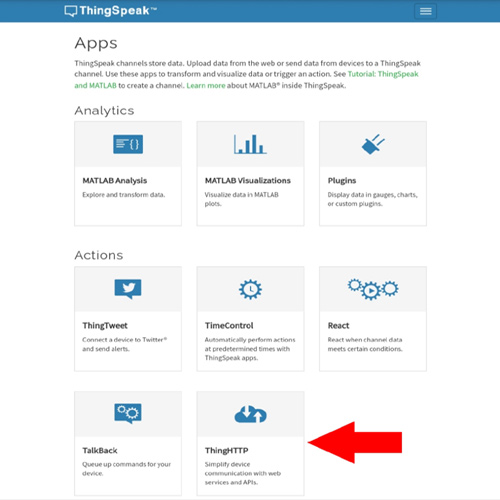
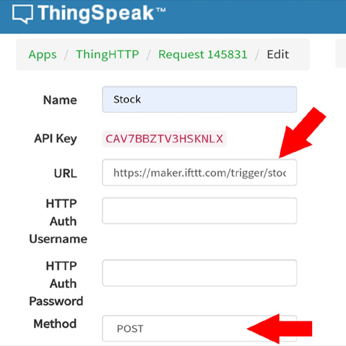
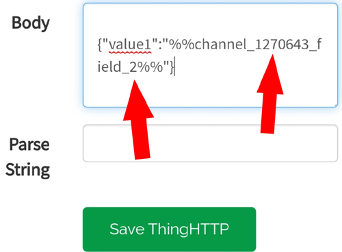
Go to thingspeak.com, then click on Apps and click on Thing HTTP. When you are there, give a name, paste the previously copied URL. Select the method as POST. In the Body, give the channel id (you will get channel id by clicking on the created channel) and change the field where we need to send mail according to the number of pieces left so I choose field 2. The image below will give you a better idea of the process.
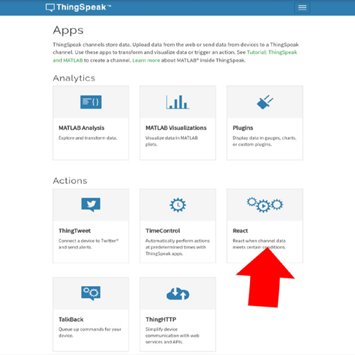
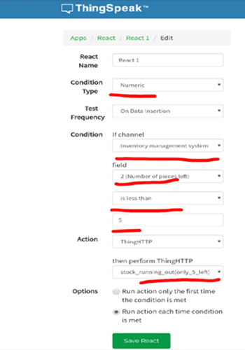
Now, go-to the apps then click react. Here give a name, select condition type as numeric, select the channel. Now, give the condition (I gave like this if the value is less than 5). You can change according to your ideas. Then select the ThingHTTP and finally click save react. All these things jointly send an email notification when the stock goes below 5 units.
That marks the end of our server setup process, and we can move onto the coding for the NodeMCU.
Automatic Inventory Monitoring and Management System - Arduino Code
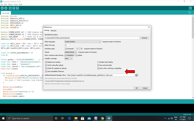
I am going to upload code to a NodeMCU board, with Arduino IDE. So, we need to add the ESP Board package in the Arduino IDE. To do this, open your Arduino IDE, then open preference from the file menu. Paste the link given below and press OK.
http://arduino.esp8266.com/stable/package_esp8266com_index.json
Then go to tools->boards->board manager. Now search for ESP and install.
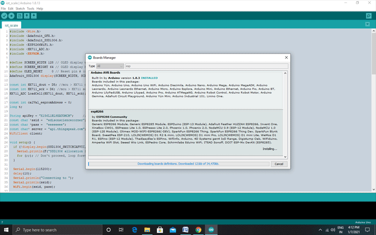
After installing this, we can start writing the program.
The complete code for the NodeMCU based Inventory Management System is given below. We start our code by including all the required libraries. The Wire library needs to be included in order to work with some of the I2C devices. Here, we are using an I2C based OLED module, so we need to include the wire library. We also need to include adafruit gfx and ssd1306 in order to work with the OLED. ESP8266WiFi is for connecting Wi-Fi to the ESP board, HX711 for taking readings from loadcell, and EEPROM for storing the values in esp’s EEPROM.
#include <Wire.h>
#include <Adafruit_GFX.h>
#include <Adafruit_SSD1306.h>
#include <ESP8266WiFi.h>
#include <HX711_ADC.h>
#include <EEPROM.h>
Next, in four lines, we defined the properties of OLED display, change these according to your display (all lines commented in the code)
#define SCREEN_WIDTH 128
#define SCREEN_HEIGHT 64
#define OLED_RESET
Adafruit_SSD1306 display (SCREEN_WIDTH, SCREEN_HEIGHT, &Wire, OLED_RESET);
Then we have defined pins for the modules and assigned values zero to the EEPROM address. HX711_ADC loadcell function is for setting the Dout and clock pin. Also, we have defined integers to hold the EEPROM address.
const int HX711_dout = D5;
const int HX711_sck = D6;
HX711_ADC LoadCell(HX711_dout, HX711_sck);
const int calVal_eepromAdress = 0;
long t;
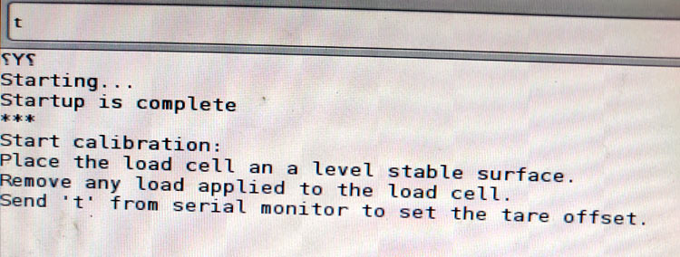
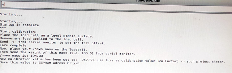
To calibrate and store that calibration value in EEPROM, first, go to file > examples> HX 711_ADC, then select the calibration code. Before uploading the code, place the balance on a stable plane surface. Then upload the code to Arduino and open the serial monitor. Then change the baud rate to 572600. Now, the monitor asks to offset the weight, for that, we need to press t.
Now, we need to place the known weight on the balance. In my case that is 194gm. After placing the known weight, type the numerical value for the weight on the serial monitor and hit enter.
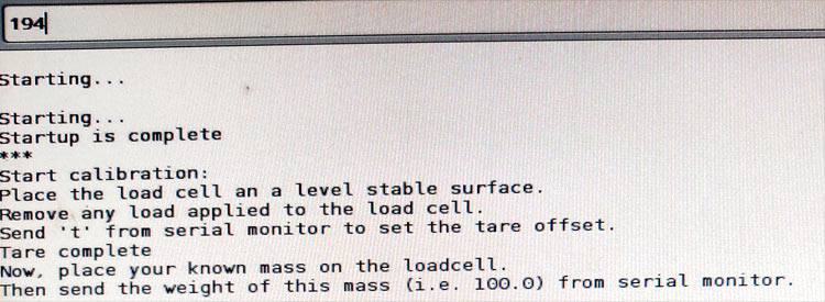
Now monitor asks you whether you want to save the value in EEPROM or not, type y. Now, we can see the weight on the serial monitor.
In this way, the NodeMCU automatically picks the calibration value from EEPROM. Next, we need to set a string and characters for the API key SSID and the password. Use your own credentials in the SSID and pass section.
String apiKey = "ABCDEFGHI";
const char *ssid =  "BALANCE";
const char *pass =  "PASSWORD";
const char* server = "api.thingspeak.com";
WiFiClient client;
Next, in the setup section, I entered the I2C address of my display. Then I started the serial communications with a baud rate of 112500 for better debugging. Also, I started the Wi-Fi communication, load cell, and also EEPROM.
if (!display.begin(SSD1306_SWITCHCAPVCC, 0x3C))
Serial.begin(115200);
LoadCell.begin();
EEPROM.begin(512);
Next, in the loop section, first, we check if any data from the load cell is available using LoadCell.update. If available, we read and store that data.
if (millis() > t + serialPrintInterval) {
      float i = LoadCell.getData();
Then, I configured the display so that the display shows the values. In this way, I can display the loadcell values. In the same way, we can display the value of the number of pieces left in our homemade inventory.
      display.clearDisplay();
      display.setTextColor(WHITE);
      display.setTextSize(1);
      display.setCursor(5, 0);
      display.print("TOTAL WEIGHT ");
      display.setCursor(10, 15);
      display.setTextSize(1);
      display.print(i);
      display.print("gm");
      display.display();
I defined a float variable and an integer. Float (w) is for storing the weight of one piece (we need to enter this value manually) and integer (k) is for storing the result of the calculation. The calculation is very simple. We get the number of pieces (k) by dividing the total weight (i) by the weight of one piece(w)
float  i = LoadCell.getData();
 float  w
int k = i / w;
The following lines of code are for sending the data to ThingSpeak cloud.
if (client.connect(server, 80))
      {
        String postStr = apiKey;
        postStr += "&field1=";
        postStr += String(i);
        postStr += "&field2=";
        postStr += String(k);
        postStr += "\r\n\r\n";
        client.print("POST /update HTTP/1.1\n");
        client.print("Host: api.thingspeak.com\n");
        client.print("Connection: close\n");
        client.print("X-THINGSPEAKAPIKEY: " + apiKey + "\n");
        client.print("Content-Type: application/x-www-form-urlencoded\n");
        client.print("Content-Length: ");
        client.print(postStr.length());
        client.print("\n\n");
        client.print(postStr);
        Serial.println(" Sending to Thingspeak.");
      }
That’s all about the coding section. Now, just select the board NodeMCU12E compile and upload.
Please find the complete working of this project in the video linked at the bottom of this page. If you have questions regarding the article, you can leave them in the comment section below.
#include <Wire.h>
#include <Adafruit_GFX.h>
#include <Adafruit_SSD1306.h>
#include <ESP8266WiFi.h>
#include <HX711_ADC.h>
#include <EEPROM.h>
#define SCREEN_WIDTH 128 // OLED display width, in pixels
#define SCREEN_HEIGHT 64 // OLED display height, in pixels
#define OLED_RESET 0 // Reset pin # (or -1 if sharing Arduino reset pin)
Adafruit_SSD1306 display(SCREEN_WIDTH, SCREEN_HEIGHT, &Wire, OLED_RESET);
const int HX711_dout = D5; //mcu > HX711 dout pin
const int HX711_sck = D6; //mcu > HX711 sck pin
HX711_ADC LoadCell(HX711_dout, HX711_sck);
const int calVal_eepromAdress = 0;
long t;
String apiKey = "X156L1RL9XAUOMCM"; // Enter your Write API key from ThingSpeak
const char *ssid = "edisonsciencecorner"; // replace with your wifi ssid and wpa2 key
const char *pass = "eeeeeeee";
const char* server = "api.thingspeak.com";
WiFiClient client;
void setup() {
if (!display.begin(SSD1306_SWITCHCAPVCC, 0x3C)) { // Address 0x3D for 128x64
Serial.println(F("SSD1306 allocation failed"));
for (;;); // Don't proceed, loop forever
}
Serial.begin(115200);
delay(10);
Serial.println("Connecting to ");
Serial.println(ssid);
WiFi.begin(ssid, pass);
while (WiFi.status() != WL_CONNECTED)
{
delay(500);
Serial.print(".");
}
Serial.println("");
Serial.println("WiFi connected");
LoadCell.begin();
float calibrationValue;// calibration value (see example file "Calibration.ino")
#if defined(ESP8266)|| defined(ESP32)
EEPROM.begin(512); // uncomment this if you use ESP8266/ESP32 and want to fetch the calibration value from eeprom
#endif
EEPROM.get(calVal_eepromAdress, calibrationValue); // uncomment this if you want to fetch the calibration value from eeprom
long stabilizingtime = 2000; // preciscion right after power-up can be improved by adding a few seconds of stabilizing time
boolean _tare = true; //set this to false if you don't want tare to be performed in the next step
LoadCell.start(stabilizingtime, _tare);
if (LoadCell.getTareTimeoutFlag()) {
Serial.println("Timeout, check MCU>HX711 wiring and pin designations");
while (1);
}
else {
LoadCell.setCalFactor(calibrationValue); // set calibration value (float)
Serial.println("Startup is complete");
}
}
void loop() {
static boolean newDataReady = 0;
const int serialPrintInterval = 0; //increase value to slow down serial print activity
// check for new data/start next conversion:
if (LoadCell.update()) newDataReady = true;
// get smoothed value from the dataset:
if (newDataReady) {
if (millis() > t + serialPrintInterval) {
float i = LoadCell.getData();
Serial.print("Load_cell output val: ");
Serial.println(i);
float w = 5; //weight of one piece
display.clearDisplay();
display.setTextColor(WHITE);
display.setTextSize(1);
display.setCursor(5, 0);
display.print("TOTAL WEIGHT ");
display.setCursor(10, 15);
display.setTextSize(1);
display.print(i);
display.print("gm");
display.display();
int k = i / w;
display.setTextSize(1);
display.setCursor(0, 30);
display.print("PIECES LEFT ");
display.setCursor(30, 45);
display.setTextSize(2);
display.print(k);
display.print(" Nos");
display.display();
if (client.connect(server, 80)) // "184.106.153.149" or api.thingspeak.com
{
String postStr = apiKey;
postStr += "&field1=";
postStr += String(i);
postStr += "&field2=";
postStr += String(k);
postStr += "\r\n\r\n";
client.print("POST /update HTTP/1.1\n");
client.print("Host: api.thingspeak.com\n");
client.print("Connection: close\n");
client.print("X-THINGSPEAKAPIKEY: " + apiKey + "\n");
client.print("Content-Type: application/x-www-form-urlencoded\n");
client.print("Content-Length: ");
client.print(postStr.length());
client.print("\n\n");
client.print(postStr);
Serial.println(" Sending to Thingspeak.");
}
client.stop();
Serial.println("Waiting...");
// thingspeak needs minimum 15 sec delay between updates
delay(10);
newDataReady = 0;
t = millis();
}
}
}


 Platform")


