


In a productive environment, sorting of products can be a very difficult process. Continuous manual sorting creates issues and takes a considerable amount of time and manpower. So in this tutorial, we are going to build an IoT-based Colour Sorting Machine using NodeMCU-ESP8266, TCS3200 Colour Sensor, and two Servo Motors, as the title says it will sort the things according to their colour. The TCS3200 Colour Sensor is responsible for sensing the colour of an object and two servo motors are used to put them into the respective predefined colour box. And as it is IoT enabled, the number of products for each colour will be displayed on the Thingspeak control panel.
For the demonstration purpose, we will build a simple colour sorting setup using cardboard. The boxes and the setup both will be in the fixed position and the servo motor will be used to move the sorter to put the ball in the respective colour box. And we will be using the ThingSpeak and ESP8266 to do so. We have previously used the TCS3200 Colour Sensor with NodeMCU to build an IoT Based Currency Counter, you can check that out if that peaks your interest.
TCS3200 Colour Sensor
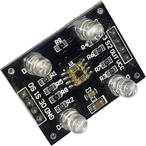
TCS3200 is a colour sensor that can detect a wide variety of colours based on their wavelength. It uses a TAOS TCS3200 RGB sensor chip to detect colour frequency. This sensor also contains four white LEDs that light up the object in front of it. The TCS3200 chip has an 8 x 8 array of photodiodes (a total of 64 photodiodes). From these 64 photodiodes, 16 photodiodes have Red filters over them, 16 photodiodes have Green filters, 16 photodiodes have Blue filters, and the remaining 16 photodiodes are clear with No filters.
In this module, 16 photodiodes of the same colour are connected in parallel. The control pins S2 and S3 are used to select the array of photodiodes. For example, we can read the red colour photodiodes by setting the S2 and S3 to the low logic level. The complete table is given below:
|
S2 |
S3 |
Photodiode Type |
|
0 |
0 |
Red |
|
0 |
1 |
Blue |
|
1 |
0 |
Clear |
|
1 |
1 |
Green |
The remaining two control pins i.e. S0 and S1 are used for scaling the output frequency. The output frequency can be scaled to three different preset values of 2%, 20%, or 100%. The pin logic for setting the output frequency is given in the below table:
|
S0 |
S1 |
Output Frequency |
|
0 |
0 |
Power Down |
|
0 |
1 |
2% |
|
1 |
0 |
20% |
|
1 |
1 |
100% |
Specifications of TCS3200 RGB Colour Sensor:
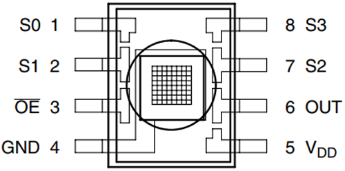
Before proceeding further, let’s cover up the specification of this module. This module has a working voltage of 3V to 5V which means it can be directly interfaced with any microcontroller, and that is why it’s a perfect choice for our NodeMCU, which uses a 3.3V logic level. Other than power and ground, it has an enable pin E0, by pulling it low or high, we can disable or enable the chip. The OUT pin is used to provide the output frequency, the S0 and S1 select lines select the output frequency scaling. The S2 and S3 select lines select the photodiode type. After measuring a colour wavelength, it outputs the result as frequency, so we can directly measure the frequency and determine the colour, which reduces the intervention of an ADC. And finally, this sensor can accurately measure a test object within a distance of 1cm. If you want to learn more about its specification, you can go through the datasheet for the TCS3200 module
Materials Required for Colour Shorting Machine
- NodeMCU ESP8266 (1)
- TCS3200 Colour Sensor (1)
- Servo Motor (2)
- Jumper Wires
- Cardboard
- USB cable for power
Circuit Diagram for our Colour Sorting Machine
The circuit diagram for IoT Based Colour Sorting Machine is very simple and doesn’t require complex connections. The Circuit Diagram is given below:
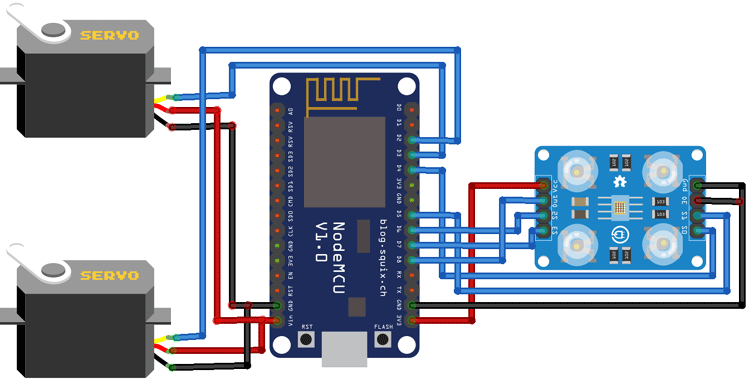
The colour sensor is powered with 3.3V and the servo motors are powered with 5V. PWM pins of both the motors are connected to D2 and D3 pins of NodeMCU. The connections for the colour sensor are given in the below table:
|
Colour Sensor Pin |
NodeMCU Pin |
|
Vcc |
3.3V |
|
GND |
GND |
|
S0 |
D4 |
|
S1 |
D5 |
|
S2 |
D6 |
|
S3 |
D7 |
|
OUT |
D8 |
|
OE |
GND |
Setting up ThingSpeak to Monitor the Progress of Colour Sorting Machine
ThingSpeak is an open-source IoT analytics platform service that allows you to aggregate, visualize, and analyze live data in the cloud. It can be used to control devices, can store sensor data, and can be used to create instant visualizations of live data, and send alerts using web services like Twitter and ThingHTTP. Previously we have built many projects with ThingsSpeake like:
Solar Powered Wi-Fi Weather Station
So, do check those out if that peaks your interest. Now let’s send our data to ThingSpeak by configuring it.
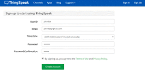
Step 1: Sign up
To send data to Thingspeak, a Thingspeak account is required. To do so, navigate to the Thingspeak website.

Click on the ‘Sign up’ option in the top right corner and fill out the required details.
After that, verify the E-mail id and click on continue.
Step 2: Create a Channel to Visualize Data
Now as you are logged in to your account, create a new channel by clicking the “New Channel” button.
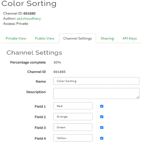
After clicking on “New Channel” enter the Name and Description of the data you want to upload on this channel.
Enter the name of data in Field1, Field2, Field3, and Field4. If you want to use more field than two, then you can check the box next to the Field option and enter the name and description of the channel.
After that, click on the ‘Save Channel’ button to complete the channel creation process.
Thingspeak usually shows data in Graph format, but it also provides an option to visualize data using different widgets. To add a widget, click on the ‘Add Widgets’ option and choose the widget you want to use. In this project, I am using the ‘Numeric Display’ widget.
Step 3: API Key
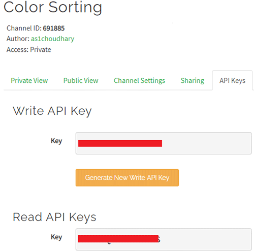
To send data to ThingSpeak, we need a unique API key, which we will use later in code to send the data to ThingSpeak Website.
Click on the “API Keys” option to get a unique API key for uploading sensor data. Now copy “Write API Key.”
Arduino Code used to Control the Colour Sorting Machine
The complete code for IoT Based Colour Sorting Machine is given at the end of the document. Here we are explaining the complete code step by step.
We will be using ThingSpeak with Arduino IDE, so as usual, the first step will be including all the required libraries. Thingspeak.h library can be downloaded from the link given. The Colour sensor can work without the library as we can read the colour frequency directly from the sensor pin to decide the colour.
#include <Servo.h>
#include <ESP8266WiFi.h>
#include <WiFiClient.h>;
#include <ThingSpeak.h>;
After that, in the next lines, we define the ThingSpeak API key, channel number, Wi-Fi name, and password, which we have previously saved while making the ThingSpeak account.
Const char * myWriteAPIKey = “Enter Write Key”;
unsigned long myChannelNumber = 691885;
const char *ssid = “Wi-Fi Name”;
const char *pass = “Password”; Password
Then define the servo variables. Here we are using two servo motors. The first servo motor is used to move the colour balls from the initial position to the colour sensor. The second servo motor is used to drop the colour ball into the colour bucket.
Servo pickServo;
Servo dropServo;
After that, define the colour sensor pins.
const int s0 = D4;
const int s1 = D5;
const int s2 = D6;
const int s3 = D7;
const int out = D8;
Inside the setup() function, we initialize the Serial at 9600 baud. Then define the colour sensor pins as output pins to read the frequency values also define the pins for top and bottom servo motors.
Void setup()
{
  Serial.begin(9600);
  pinMode(s0, OUTPUT);
  pinMode(s1, OUTPUT);
  pinMode(s2, OUTPUT);
  pinMode(s3, OUTPUT);
  pinMode(out, INPUT);
  pickServo.attach(D2);
  dropServo.attach(D3);
Inside the loop() function, we measure the incoming frequency of Red, Green, and Blue colour and compares these frequency readings to detect colour. The control pins S2 and S3 are used to read the colour frequencies. For example, to read the frequency of red colour, set the two pins to low logic level, to read the Blue colour, set S3 pin HIGH and S2 pin LOW, and to read the Green colour, set S2 to pin HIGH and S3 pin LOW.
Void loop()
{
  digitalWrite(s2, LOW);
  digitalWrite(s3, LOW);
  red = pulseIn(out, digitalRead(out) == HIGH ? LOW : HIGH);
  digitalWrite(s3, HIGH);
  blue = pulseIn(out, digitalRead(out) == HIGH ? LOW : HIGH);
  digitalWrite(s2, HIGH);
  green = pulseIn(out, digitalRead(out) == HIGH ? LOW : HIGH);
After getting the frequency values for Red, Green, and Blue colour, compare these values to detect the colours. Upon detecting a colour, first, move the drop servo with a particular angle to drops the colour ball to its respective box, then move the pick servo to pass the ball. Frequency values for each colour vary with distance and can be customized accordingly. After recognizing the colour, send the number of colour balls detected to ThingSpeak.
If(red<31 & red>25 & green<69 & green>63){
    colour = 1; // Red
    dropServo.write(85);
    delay(700);
    redcolour++;
    Serial.print(“Red”);
    open1();
    delay(200);
    close1();
    ThingSpeak.writeField(myChannelNumber, 1,redcolour, myWriteAPIKey);
  }
  if(green<56 & green>52 & blue<52 &blue>47){
    colour = 2; // Orange
    dropServo.write(115);
    delay(700);
    orangecolour++;
    Serial.print(“Orange”);
    open1();
    delay(200);
    close1();
    ThingSpeak.writeField(myChannelNumber, 2,orangecolour, myWriteAPIKey);
  }
  if(red<36 & red>29 & green<33 & green>26){
    dropServo.write(140);
    delay(700);
    colour = 3; // Green
    greencolour++;
    Serial.print(“Green”);
    open1();
    delay(200);
    close1();
    ThingSpeak.writeField(myChannelNumber, 3,greencolour, myWriteAPIKey);
  }
  if(red<26 & red>19 & green<32 & green>24){
    dropServo.write(170);
    delay(700);
    colour = 4; // Yellow
    yellowcolour++;
    Serial.print(“Yellow”);
    open1();
    delay(200);
    close1();
    ThingSpeak.writeField(myChannelNumber, 4,yellowcolour, myWriteAPIKey);
  }
Testing the Colour Sorting Machine
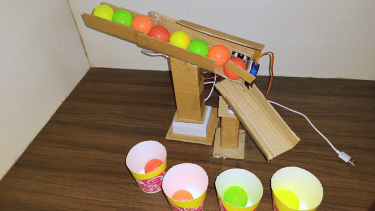
Once the code and hardware are ready, make a setup for colour sorting and mount both the servo motors and colour sensor as shown in the below image:
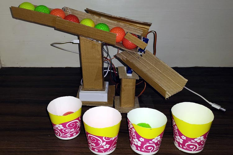
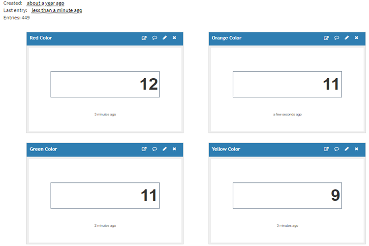
Now upload the code to the NodeMCU-ESP8266 board and your machine is ready to short the balls of different colours. The number of products for each colour will be displayed on Thingspeak as shown in the below image:
The complete code and working video are given below. Hope you enjoyed building this project and learned something useful. If you have any questions, leave them in the comment section.
#include <Servo.h>
#include <ESP8266WiFi.h>
#include <WiFiClient.h>;
#include <ThingSpeak.h>;
const char * myWriteAPIKey = "9B6ILVOYMUSVOADA";
unsigned long myChannelNumber = 691885;
const char *ssid = "Galaxy-M20"; // Enter your WiFi Name
const char *pass = "ac312124"; // Enter your WiFi Password
WiFiClient client;
Servo pickServo;
Servo dropServo;
const int s0 = D4;
const int s1 = D5;
const int s2 = D6;
const int s3 = D7;
const int out = D8;
int red = 0;
int green = 0;
int blue = 0;
int color=0;
int redcolor = 0;
int greencolor = 0;
int orangecolor = 0;
int yellowcolor = 0;
int CLOSE_ANGLE = 30; // The closing angle of the servo motor arm
int OPEN_ANGLE = 10; // The opening angle of the servo motor arm
void setup()
{
Serial.begin(9600);
pinMode(s0, OUTPUT);
pinMode(s1, OUTPUT);
pinMode(s2, OUTPUT);
pinMode(s3, OUTPUT);
pinMode(out, INPUT);
digitalWrite(s0, HIGH);
digitalWrite(s1, HIGH);
pickServo.attach(D2);
dropServo.attach(D3);
pickServo.write(30);
dropServo.write(73);
ThingSpeak.begin(client);
Serial.println("Connecting to ");
Serial.println(ssid);
WiFi.begin(ssid, pass);
while (WiFi.status() != WL_CONNECTED)
{
delay(550);
Serial.print(".");
}
Serial.println("");
Serial.println("WiFi connected");
}
void loop()
{
digitalWrite(s2, LOW);
digitalWrite(s3, LOW);
//count OUT, pRed, RED
red = pulseIn(out, digitalRead(out) == HIGH ? LOW : HIGH);
digitalWrite(s3, HIGH);
//count OUT, pBLUE, BLUE
blue = pulseIn(out, digitalRead(out) == HIGH ? LOW : HIGH);
digitalWrite(s2, HIGH);
//count OUT, pGreen, GREEN
green = pulseIn(out, digitalRead(out) == HIGH ? LOW : HIGH);
Serial.print("R Intensity:");
Serial.print(red, DEC);
Serial.print(" G Intensity: ");
Serial.print(green, DEC);
Serial.print(" B Intensity : ");
Serial.print(blue, DEC);
if(red<39 & red>29 & green<93 & green>83 &blue<78 & blue>69){
dropServo.write(73);
delay(700);
redcolor++;
Serial.print("Red");
open1();
delay(200);
close1();
ThingSpeak.writeField(myChannelNumber, 1,redcolor, myWriteAPIKey);
}
if(green<75 & green>65 & blue<68 &blue>60){
dropServo.write(107);
delay(700);
orangecolor++;
Serial.print("Orange");
open1();
delay(200);
close1();
ThingSpeak.writeField(myChannelNumber, 2,orangecolor, myWriteAPIKey);
}
if(red<46 & red>36 & green<46 & green>37){
dropServo.write(132);
delay(700);
greencolor++;
Serial.print("Green");
open1();
delay(200);
close1();
ThingSpeak.writeField(myChannelNumber, 3,greencolor, myWriteAPIKey);
}
if(red<34 & red>25 & green<37 & green>28 & blue<53 & blue>43){
dropServo.write(162);
delay(700);
yellowcolor++;
Serial.print("Yellow");
open1();
delay(200);
close1();
ThingSpeak.writeField(myChannelNumber, 4,yellowcolor, myWriteAPIKey);
}
Serial.println();
// delay(1000);
}
void open1(){
pickServo.write(OPEN_ANGLE); // Send the command to the servo motor to open the trap door
}
void close1(){
pickServo.write(CLOSE_ANGLE); // Send te command to the servo motor to close the trap door
}


