


Most of you might know about the robotics project and its working using microcontrollers. In today’s time, such DIY robotics projects are so popular and most demanded. Hence, we decided to make a new Robotic project Bluetooth controlled robot car using Arduino which is very simple and perfectly compatible with students, hobbyists, and beginners in embedded Technology. By adding more technology, these are a type of futuristic robots that will be used for different purposes in different sectors like firefighting bots, surveillance robots, etc.
In this project, we will make a wirelessly Bluetooth controlled robot car using Arduino as the microcontroller. It will be an exciting project which is a combination of wireless communication, robotics, and electronics. We can able to control the robot using our smartphone, only we have to just install an App available on Playstore (see later). We are integrating a Bluetooth module for seamless wireless communication between the robot car and Bluetooth-enabled devices.
We have previously created some other IoT based robotics projects:
- Wi-Fi Controlled Robot using NodeMCU
- Gesture Controlled Robot Using Arduino
- ESP32 CAM Based Surveillance Robot using Arduino IDE
Components required to build Wireless Robot Car
- Arduino UNO *1
- L298N 2A Motor driver Module *1
- HC-05 Bluetooth Module *1
- 5v Geared Motors *2
- Power Supply
- Robot Chassis
- Connecting Wires
- Controller App and Smartphone
L298N Motor Driver Pinout
The Module functions as a driver/controller for the wheel-geared motors, enabling control over both their direction and speed. As we are not utilizing the PWM signal generated by Arduino to regulate the speed, the geared motors will operate at their maximum speed because we keep the current state of the sorted PWM pins (ENA & ENB) present on the Board. Hence, the driver module is utilized only to alter the rotation direction of the motor, allowing the bot to move in all four directions.
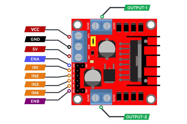
It consists mainly of all the connections from connecting the motor to controlling it.
- VCC: Pin used to provide the supply to the board. Its operating supply voltage range from 4-46 volts.
- GND: Pin used to connect the board to the ground of the supply. To ensure the proper functioning of the board when interfacing it with an Arduino that is already powered, it is essential to establish a connection between the ground of the board and the ground of the Arduino.
- 5V: Since the board has an inbuilt 5-volt voltage regulator. This pin provides a constant 5-volt output to power internal logic circuitry as well as to power other devices simultaneously like microcontrollers.
- ENA & ENB: These pins are used to control the speed of the motor. Pulling the specified pins HIGH will initiate the rotation of the motors at maximum Speed, whereas pulling them LOW will halt their movement. However, by utilizing Pulse Width Modulation (PWM), it becomes possible to control the speed of the motors. Typically, the module is equipped with a jumper on these pins. When the jumper is installed, the motors operate at maximum speed. If you desire to programmatically regulate the motor speed, removing the jumpers and connecting the pins to the Arduino's PWM-enabled pins is necessary.
- IN1 & IN2: These pins are used to control the motors’ spinning direction and to stop them. These two pins are assigned to control one side motor while the IN3 & IN4 are assigned to control the other motor. Putting logic HIGH-LOW to IN1 & IN2 will create a spin in the forward direction while LOW-HIGH reverses the spin. Similarly, the same is applicable for IN3 & IN 4. Putting logic LOW-LOW & HIGH-HIGH will cause the motor to stop. And these pins are connected to the digital pins of the Arduino.
- OUT-1 & OUT-2: This pin is used to connect to the Motors. One motor is connected to OUT-1 & another one to OUT-2. You can connect the motor up to a voltage range of 5v to 35volt. Keep in mind that you will get approximately a 2-volt decrement by whatever voltage you are applied to VCC.
HC-05 Bluetooth Pinout
It is a widely used module in electronic projects for wireless communication. It uses serial UART communication for data transfer.
The Module can work in two modes:
Master mode: It can share data with all slaves.
Slave mode: It receives data from a master Bluetooth.
Here, our Bluetooth module is working as a slave while the smartphone is a master.
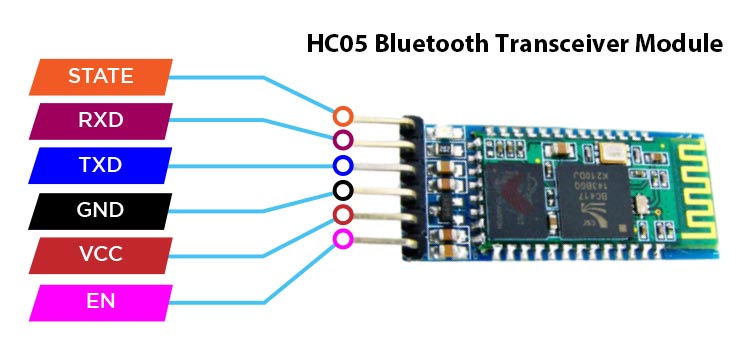
It consists of 6 pins which are STATE, RXD, TXD, GND, VCC, and EN as mentioned on the back of the module.
- STATE pin: This pin defines the state of the module whether it is paired or not with another device.
- RxD pin: This pin uses serial UART communication. This pin is used to send AT command when the module is in command mode.
- TxD pin: This pin uses serial UART communication. This pin is used to push out responses to AT command when the module is in command mode.
- Vcc pin: This pin is used to supply power to the module to make it work. It is typically connected to the 5V pin on the Arduino board. Its voltage range lies between 3.6v to 5v.
- GND pin: This pin is used to connect the module to the ground of the Arduino board.
- EN pin: This pin is used to switch between command and data mode. The module will be in command mode if this pin is set to HIGH. Similarly, the module will be in data mode if this pin is set to LOW.
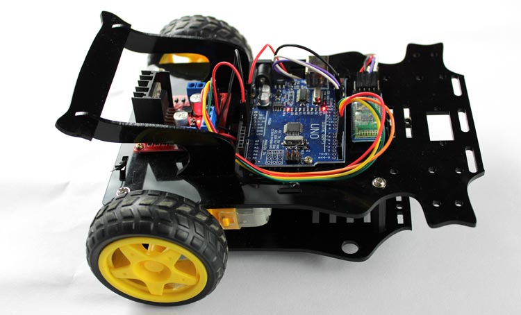
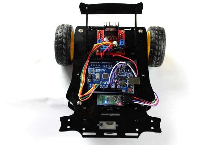
Chassis Assembly of Robot Car
We have used an acrylic laser cut sheet with all necessary fittings compatible. It’s precisely cut with all the spaces provided for components fittings using screwdrivers. You can also refer to various online platforms to Buy Such types of chassis prototypes
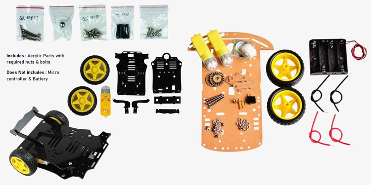
These come with all required parts like motors, battery holders, all wheels, and Screws. You just need to pick and screw it properly. You can also refer to manufacturer assembling videos. These are low cost, highly durable with precise fitting. So, you don’t need to worry about the fittings.
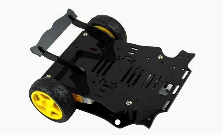
Have a look at my Chassis prototype after all fittings :
Arduino Bluetooth Controlled Robot Circuit Diagram
Below is the comprehensive circuit diagram for the Bluetooth-controlled Robot Car, featuring a straightforward design that is easy to understand and implement.
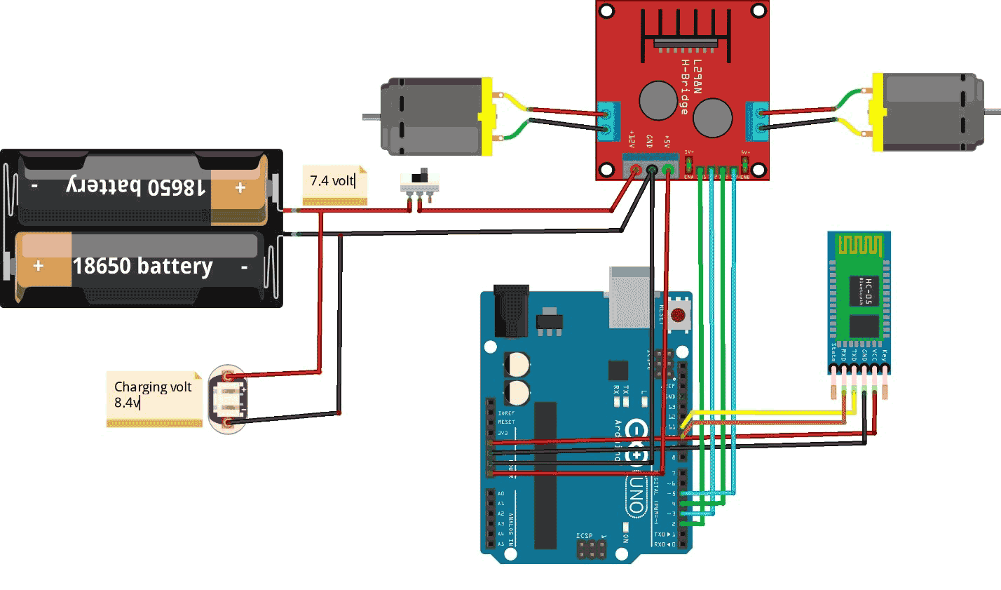
Let’s look at the connections:
Firstly, connect the Bluetooth HC-05 module to Arduino and check for the data received on the serial monitor of the IDE. In my case, the Txd and Rxd of HC-05 are connected to 11 and 10 digital pins respectively. And BT module gets power from Arduino by connecting power pins to respective Arduino power pins.
The Arduino gets power from the L298N board from the 5v output terminal and Ground.
Connections for L298N:
As we already see the pinouts description of the L298N motor driver. So, it now becomes easy to interface it with Arduino.
By connecting the positive terminal of the battery to the VCC of the driver board we can power our motor driver, we employ a 2S lithium-ion battery with an output voltage of approximately 7.4 volts. This choice is made because we are utilizing BO-geared motors that operate within a voltage range of 3 to 12 volts, a decrease of approximately 2 volts at the output motor terminal by internal circuitry of the board has minimal impact on the motor's functionality. Hence, motors will get a nearby 5.5 -6 volts.
Now, to interface the digital direction control pins to the Arduino, just connect any four digital pins of the Arduino to the IN1, IN2, IN3 & IN4 pins of the driver board and customize the code according to the correct Arduino PINs.
The actual connections and functioning appear as follows:
App Configuration to interface Bot with Smartphone
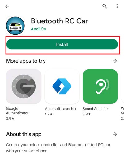
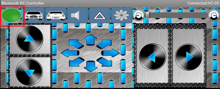
Interfacing a robot car with our Smartphone is a very easy process, only we have to download an Application from Playstore named” Bluetooth RC Car”. The App has a prebuilt interface to control any type of Bluetooth RC Robot. The application has graphical buttons, sliders, or even sensors (e.g., an accelerometer) for intuitive control. It has various other inbuilt features to control the different functions like turning ON/OFF the front and rear lights of the Car and soon.
- Go to Playstore on your Android smartphone and search for “Bluetooth RC Car”. You will find an app that looks like this:
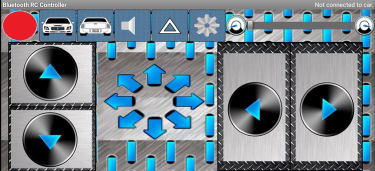
- Install the app & open it. You will see an attractive Interface that makes it easy to control the Car.
Working of Robot Car - Controlled by Smartphone
As we know the Arduino is the Brain of the Robot car. It is programmed using the Arduino IDE (Integrated Development Environment) to receive and process commands sent via Bluetooth. The programming code is written to interpret the received signals and translate them into specific actions for the motors, such as moving forward, backward, turning left or right, and stopping.
Before proceeding, ensure that the switch of the robot car is turned ON and verify that the batteries are fully charged. Additionally, carefully inspect all connections to ensure they are secure and not loose.
The wireless interfacing between the robot and the smartphone is facilitated by the Bluetooth connectivity feature of the bot which is implemented by using the HC-05 module.
On our Bluetooth Enabled Smartphone, the mobile App has a control interface. This interface allows the user to send commands to the robot car, specifying the desired actions or movements.
- Upload the Code to Arduino and check the blinking LEDs of the BT module.
- Open the Application, turn on the Bluetooth of the smartphone, and paired App with BT module named “HC-05”.
- If the Application is Successfully paired, the red mark at the left top corner will change to Green.
Once the connection is established and the control interface is ready, the user can wirelessly control the robot car using the Smartphone device. The control signals are transmitted over Bluetooth and received by the Arduino board, which then interprets them and controls the motors accordingly, executing the desired movements.
Arduino Code for Bluetooth-Controlled Robot Car
We know that Bluetooth Module uses Serial Communication to communicate data. The program reads the Bluetooth Module data available on the serial port. According to the received command or data, the processor executes the desired movement Function.
We have included SoftwareSerial Library to define the Serial Communication Pins to communicate with BT Module. Inside the code, Pin 11 is defined as RX, then it must be connected to the TxD of BT Module. Similarly, pin 10 to the RxD of BT Module. Also, we have defined the IN1, IN2, IN3 & IN4 pins as 2,3,4 & 5 digital pins of the Arduino.
#include<SoftwareSerial.h>
#define IN1 2
#define IN2 3
#define IN3 4
#define IN4 5
//#define EN1 6
//#define EN2 5
SoftwareSerial bt(11, 10); // RX, TX
char data;
Inside setup() function, we initialize the hardware serial communication at a baud rate of 9600 whereas the function bt.begin() initializes Bluetooth communication at the same baud rate. We have also defined Pinmodes and written all direction control pins initially as LOW to halt any kind of movement of Motors.
void setup() {
  Serial.begin(9600);
  pinMode(IN1, OUTPUT);
  pinMode(IN2, OUTPUT);
  pinMode(IN3, OUTPUT);
  pinMode(IN4, OUTPUT);
  //pinMode(EN1, OUTPUT);
  //pinMode(EN2, OUTPUT);
  digitalWrite(IN1, LOW);
  digitalWrite(IN2, LOW);
  digitalWrite(IN3, LOW);
  digitalWrite(IN4, LOW);
  //analogWrite(EN1,63);
  //analogWrite(EN2,63);
  bt.begin(9600);
}
Inside Loop() Function, we are checking for the data available on the serial port and printing it to the Serial Monitor to check the Functionality of the BT module. Send any character terminal command by connecting it to your smartphone to display it on Serial Monitor.
We are comparing the received data using Switch Case statements and if the condition is true, the statement will get executed.
We are calling five different movement functions inside switch statements that we have defined outside the loop.
void loop() {
   while (bt.available())   {
      { data = bt.read();
        Serial.println(data);}
      switch (data)
       {
          case 'F':
            //Serial.println("Forward");
            forward();
            break;
          case 'B':
           //Serial.println("Reverse");
            reverse();
            break;
          case 'L':
           //Serial.println("Left");
            left();
            break;
          case 'R':
            //Serial.println("Right");
            right();
            break;
          case 'S':
            //Serial.println("Stop");
            stoprobot();
            break;
          }
      }
       if (bt.available() < 0)
        {
         //Serial.println("No Bluetooth Data ");
        }
  delay(100);
}
Movement Functions: We have defined four types of movement functions and a Stop function. Configuring the four digital pins (IN1, IN2, IN3, IN4) will control all directions of movement. Providing HIGH-LOW commands is essential to spin the wheels. Sometimes developers have to adjust these commands to set the True directions according to their Hardware connections.
void forward() {
  digitalWrite(IN1, HIGH);
  digitalWrite(IN2, LOW);
  digitalWrite(IN3, LOW);
  digitalWrite(IN4, HIGH);
  delay(20);
}
void reverse() {
  digitalWrite(IN1, LOW);
  digitalWrite(IN2, HIGH);
  digitalWrite(IN3, HIGH);
  digitalWrite(IN4, LOW);
  delay(20);
}
void left() {
  digitalWrite(IN1, HIGH);
  digitalWrite(IN2, LOW);
  digitalWrite(IN3, HIGH);
  digitalWrite(IN4, LOW);
  delay(20);
}
void right() {
  digitalWrite(IN1, LOW);
  digitalWrite(IN2, HIGH);
  digitalWrite(IN3, LOW);
  digitalWrite(IN4, HIGH);
  delay(20);
}
void stoprobot() {
  digitalWrite(IN1, LOW);
  digitalWrite(IN2, LOW);
  digitalWrite(IN3, LOW);
  digitalWrite(IN4, LOW);
  delay(20);
}
Hope you enjoyed the Project and learned something useful from it. If you have any questions, you can leave them in the comment section below.
#include<SoftwareSerial.h>
#define IN1 2
#define IN2 3
#define IN3 4
#define IN4 5
//#define EN1 6
//#define EN2 5
SoftwareSerial bt(11, 10); // RX, TX
char data;
void setup() {
Serial.begin(9600);
pinMode(IN1, OUTPUT);
pinMode(IN2, OUTPUT);
pinMode(IN3, OUTPUT);
pinMode(IN4, OUTPUT);
//pinMode(EN1, OUTPUT);
//pinMode(EN2, OUTPUT);
digitalWrite(IN1, LOW);
digitalWrite(IN2, LOW);
digitalWrite(IN3, LOW);
digitalWrite(IN4, LOW);
//analogWrite(EN1,63);
//analogWrite(EN2,63);
bt.begin(9600);
}
void loop()
{
while (bt.available())
{
{ data = bt.read();
Serial.println(data);}
switch (data)
{
case 'F':
//Serial.println("Forward");
forward();
break;
case 'B':
//Serial.println("Reverse");
reverse();
break;
case 'L':
//Serial.println("Left");
left();
break;
case 'R':
//Serial.println("Right");
right();
break;
case 'S':
//Serial.println("Stop");
stoprobot();
break;
}
}
if (bt.available() < 0)
{
//Serial.println("No Bluetooth Data ");
}
delay(100);
}
void forward() {
digitalWrite(IN1, HIGH);
digitalWrite(IN2, LOW);
digitalWrite(IN3, LOW);
digitalWrite(IN4, HIGH);
delay(20);
}
void reverse() {
digitalWrite(IN1, LOW);
digitalWrite(IN2, HIGH);
digitalWrite(IN3, HIGH);
digitalWrite(IN4, LOW);
delay(20);
}
void left() {
digitalWrite(IN1, HIGH);
digitalWrite(IN2, LOW);
digitalWrite(IN3, HIGH);
digitalWrite(IN4, LOW);
delay(20);
}
void right() {
digitalWrite(IN1, LOW);
digitalWrite(IN2, HIGH);
digitalWrite(IN3, LOW);
digitalWrite(IN4, HIGH);
delay(20);
}
void stoprobot() {
digitalWrite(IN1, LOW);
digitalWrite(IN2, LOW);
digitalWrite(IN3, LOW);
digitalWrite(IN4, LOW);
delay(20);
}


