


When selecting the right microcontroller for a project, you must consider cost, performance, features, power consumption, and overall size. When we consider price to performance or price to features ratio most of the shell MCUs will cost you a fortune. Especially at this time of silicon shortage. That’s where manufacturers like Megawin, Nuvoton, and STMicroelectronics come to play. Megawin with their MG82 series, Nuvoton with their N76/MS51 series, and STM with the STM8 series. While there two controllers are great, the pandemic has increased their cost considerable and when we compare the features, the Megawin Microcontrollers wins over the other two.
Megawin has multiple product lines with them. That includes their 8051 mcus based on 1T,12T/6T cores and with or without USB interface, And ARM Cortex_M0 based microcontrollers. For this tutorial, we will be using an 8051 1T core microcontroller with an impressive list of features and attractive pricing namely the MG82F6D17 microcontroller.
Difference between Megawin (MG82F6D17), Nuvoton (N76E003), and ST (STM8S003) Low cost Microcontrollers
Now arguably, which is the best low-cost microcontroller that is currently available in the market? To find that out we have compared the popular low-cost microcontroller STM8S003 from ST Microelectronics and N76E003 from Nuvoton Technology against the MG82F6D17 of Nuvoton. And you can find features comparison of low-cost microcontrollers in the below table.
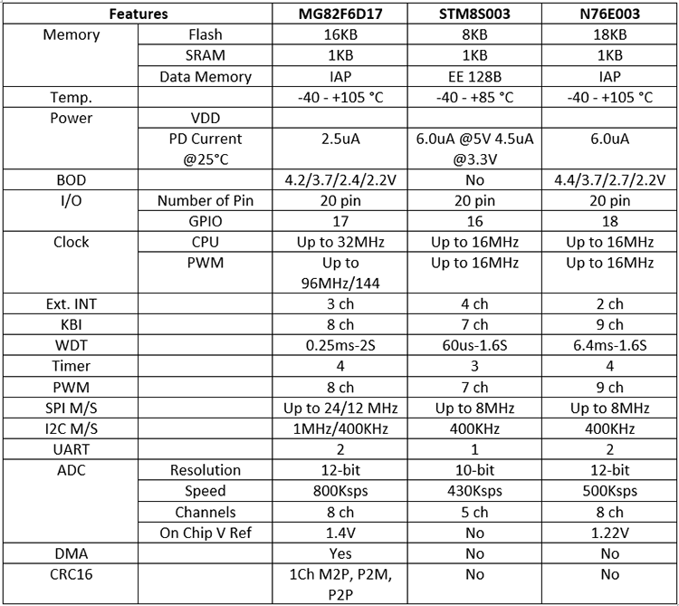
Since all our readers are from a different geographic zone and the prices of the microcontrollers are highly fluctuating, it’s hard to compare them in terms of cost. But regardless, these controllers should share the same level of price with a minimum price difference. And here in India, at the time of writing this article the cheapest of all is MG82F6D17 priced at ~Rs.50, followed by STM8S003 at ~Rs.90, and then N76E003 priced at Rs.95. Do note that these are retail prices and it will further be low when purchasing in high quantities.
Megawin MG82F6D17
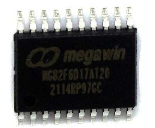
The Megawin MG82F6D17 is a 20-pin Microcontroller that is available in both SMD and through-hole packages. The one that we will be using in this tutorial is MG82F6D17A which comes in the TSSOP20 package as shown below.
Megawin’s MG82F6D17 is a low-cost microcontroller based on an advanced 1T 8051 core. MG82F617A is equipped with 16KB Flash (with configurable Flash mapping for AP, IAP and ISP), 1KB DATA RAM (256B + 768B XRAM), CPU frequency up to 32MHz, Direct Memory Access (DMA), four 16bit Timers/Counters, 8 PWM channels with up to 96MHz, 8 Channel ADC with 12bit resolution and 800Ksps sampling rate, 2x UART, SPI, TWI RTC and many more features.
MG82F6D17 is much faster and feature-rich than its competitors. The table below summarizes an actual comparison of these chips. The MG82F6D17 is available in a variety of packages DIP20, TSSOP20, SSOP20, QFN20 and in SOP8 package with reduced pins. Here for this tutorial, I will be using MG82F6D17T20, which is the TSSOP20 package variant because I already have them in stock. Feel free to use whichever variant is available for you or you are comfortable with. The above picture shows the TSSOP20 variant.
Built-in CRC16 engine ensures the integrity of the flash content. The high-frequency PWM functionality makes the MG82FD17 a better choice for industrial applications. These Incredible chips are available at a very low cost of 0.35$ at this time, and before the silicon shortage, we have been able to buy them for 0.15$.
Megawin Development Board
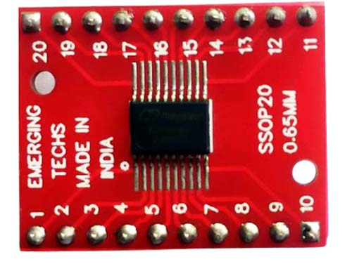
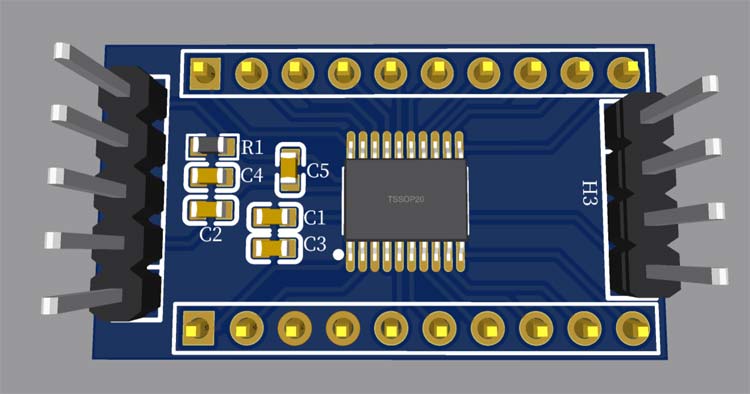
There are no special development boards needed for Megawin microcontrollers because in our cae, the MG82F6D17 only requires very few complementary components to function. Here for the tutorial I have used a TSSOP to DIP adapter board since the microcontroller I have is the TSSOP variant MG82F6D17T20. You can also find a DIP version of the chip. I used the TSSOP variant because I already have them in stock. You can find the picture of the MG82F6D17T20 soldered onto a TSSP20 to DIP adapter board below.
Here below is the schematics and Gerber file for the MG82F6D17 Development board, in case you are interested to make a development board. The development board is not at all necessary. You can also work with the microcontroller and a breadboard.
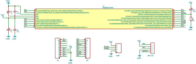
3D View
If you are interested to build the development board you can download the Gerber files from the following link:
Download Megawin Development Board PCB Gerber File
Megawin Microcontroller Programmers
For Programming, we have multiple options. We can either use a Megawin OCD ICE Debugger or Megawin 8051 ISP Programmer or a USB to TTL converter. Megawin microcontrollers came with a factory ISP bootloader which will allow us to programme the microcontroller with either the ISP programmer or a cheap and affordable USB to TTL adapter. As long as the ISP code exists this way of programming is possible. The factory ISP code uses around 1.5KB of the chip. If you want to use this flash area for the code all you have to do is use an OCD ICE adapter. Or you can even write your own bootloader for the MG82F6D17. But keep in mind that once you removed the bootloader you will need the OCD ICE to program the chip until you reflash the bootloader.
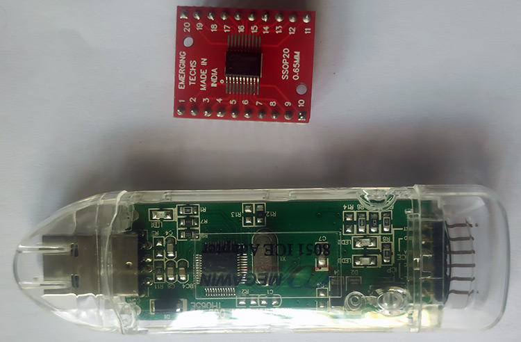
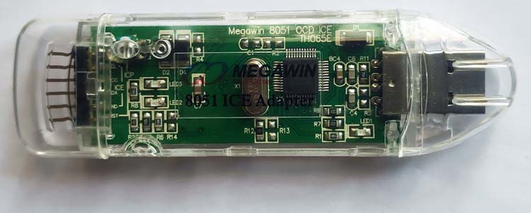
Here is the image of the Megawin OCD ICE Adapter. With an OCD ICE adapter, you cannot only program the microcontroller but also can debug the chip step by step. This will allow us to find faults and optimize the code more efficiently
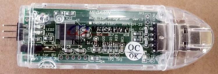
Similarly, here is the picture of a Megawin ISP programmer. Here you can see that the ISP programmer only has 3 pins. You may wonder why. That’s because the Megawin ISP is a one-wire protocol and it only needs one pin to programme the chip. We will only need the OCD SDA pin and the power pins. This programmer is sometimes also referred to as Megawin ICP Programmer.
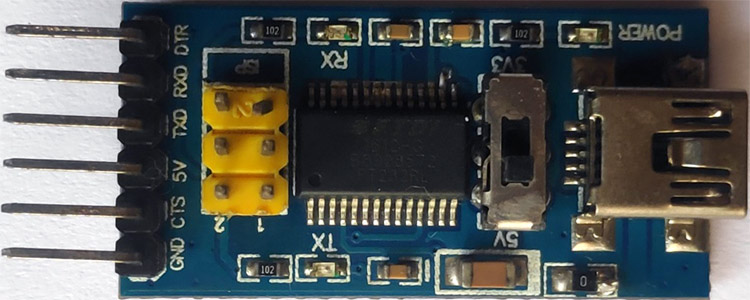
Let’s look at the cheapest option to programme the MG82F6D17 microcontroller. As mentioned above you can also use a USB to TTL converter to programme the MG82F6D17 chip. All you have to do is connect the TX0 of the chip to RX of the USB-TTL converter and RX0 of the chip to the TX pin of the converter. There are multiple USB to TTL converter boards available, which are based on popular converter chips like FT232 from FTDI, CP2102 from Silicon Labs, CH340 series from WCH, PL2303 From Prolific etc. You can use either one of them with Megawin MG82F6D17. Here I have used a converter based on the FT232RL chip from FTDI. You can find the picture of that specific converter board below.
Megawin Software
For the development process, you will need the following Software packages
1. An IDE and Compiler
2. BSP (board support package)
- Megawin BSP / SPL package
- MG82F6D17 Driver
3. ISP/ICP Programmer UI
IDE and Compiler for Megawin Microcontrollers
Proper documentation and software support is very essential for any microcontroller or embedded system development. While many of the major microcontroller manufacturers provide their own IDE / Development environments such as Microchip studio for AVR and SAMD devices and MPLab IDE for Microchip PCI line up and STM32 Cube IDE for STM32 series chips etc. But unfortunately, Megawin doesn’t have its own IDE. But that doesn’t mean it’s difficult to develop around the Megawin microcontrollers. For that, we will be using Keil µVison IDE with a C51 compiler. Also, the OCD or on-chip debugging is possible with the Keil µVison with the help of the Megawin OCD ICE adapter. Even though the Keil µVision is not free, we can use it as an evaluation version without a licence with few limitations.
Since MG82F6D17 is an 8051 device we could use other IDEs like Code block or MCU51 IDE. But we choose the Keil µVision IDE because there is a BSP (board support package) or SPL (standard peripheral library) available from Megawin. Which consists of example codes and peripheral libraries which will make the development a lot easier.
Board Support Package or Standard Peripheral Libraries
Most manufacturers provide a set of libraries for the developers to make code development much easier and more efficient. These libraries or support packages are called Board support package (BSP) or Standard Peripheral Libraries (SPL). Megawin also provides such a care package for us which can be downloaded from the link provided above. It contains the SPLs as well as example codes, which will make it easier to understand the programming structure bit easier. With this tutorial, we will be using this BSP.
ISP ISCP Programmer
Once the code is compiled into the binary, we have multiple ways to burn or load the firmware into the chip. One way is to load it directly from the Keil IDE. For this, we would need the Megawin OCD ICE adapter. This way is much easier when debugging the code. We don’t need to go through any other hustle to program it and debug it.
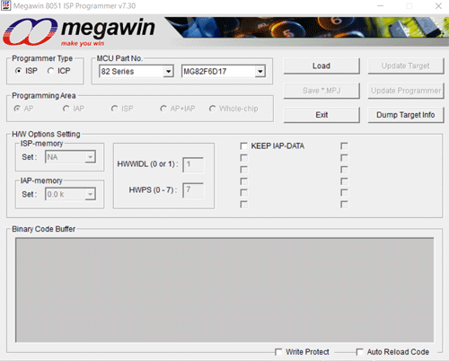
The second way is to use the ISP ICP Programmer UI with the Megawin ISP Adapter. This method is more suitable for bulk programming once the development is complete. And here is how the interface looks like
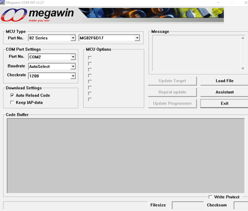
The third way is to use a USB to TTL adapter. This will be a more suitable way if you don’t have an OCD ICE/ISP programmer in hand. The MG82FD617 comes with an ISP bootloader from the factory. This enables us to program it through the UART port without an OCD ICE or ISP adapter. If you don’t mind reserving / not using the 1.5KB of the flash, which is used by the bootloader this way is cheaper and easier. For this, we will be using Megawin COM ISP Programmer. And the interface looks like this
Downloading and Installing Software for Megawin
Links to download all the necessary software is given above. Please download all the packages the keep them ready. In the next step, we will be showing how to instal, and set up all those software.
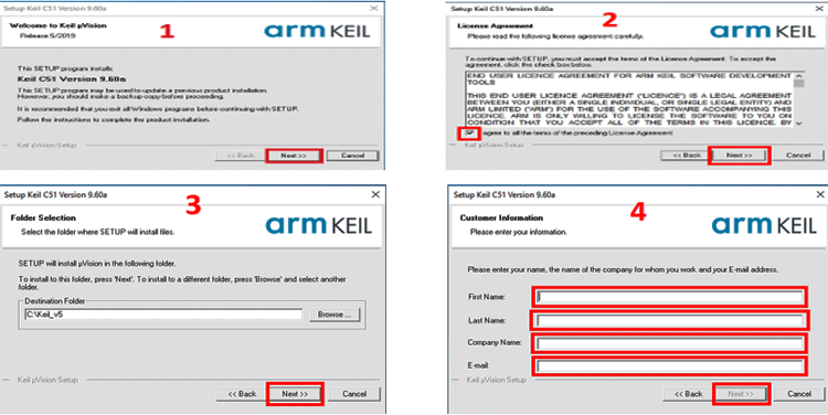
Installing Keil µVison C51
After downloading Keil µVison setup from the given link open the setup file and follow the steps as shown in the screenshots
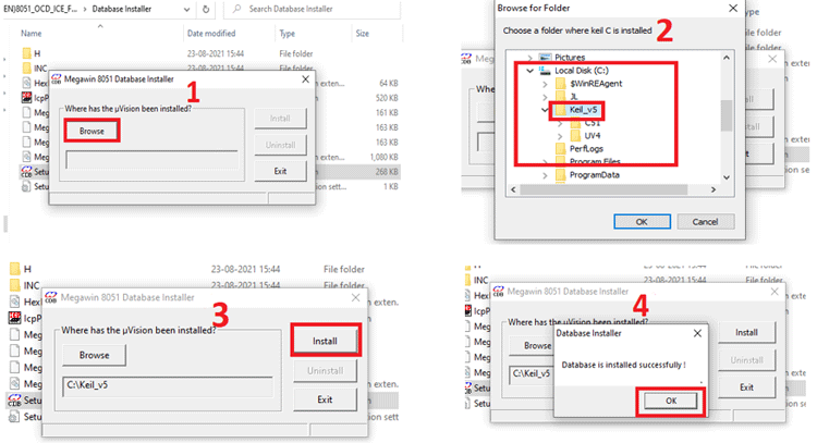
Installing Megawin Chip Database
To program Megawin devices you need to install a chip database to Keil Which will add all the needed device definitions to the µVison IDE. For The first download 8051_OCD_ICE_For_Keil zip file from the given link. Extract it, open the setup.exe, and follow the procedure as per shown in the pictures
Installing Programming Tools
The programming tools can be run directly, no need to install them. Download the files, extract them and run the exe. That’s it. There is no need to install any driver for OCD ICE or ISP programmer. For UART programming install the appropriate driver for the USB to TTL converter you are using, if it’s already not installed.
First Project – Let’s Blink an LED
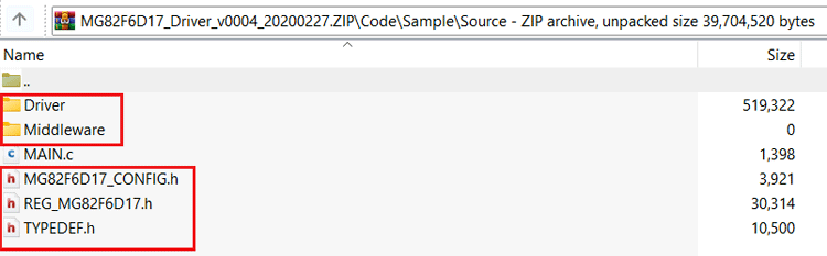
To start let’s see how to create a new project for MG82F6D17 in Keil. First, create a folder for the project with the desired name. and create a subfolder within this folder with the name Source. Now, do open the MG82F6D17 Driver zip file and extract the following files from Code\Sample\Source to the newly created source folder.
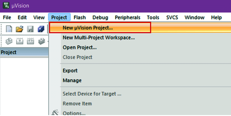
Now open the Keil µVison IDE and select New µVison project from the Project menu.
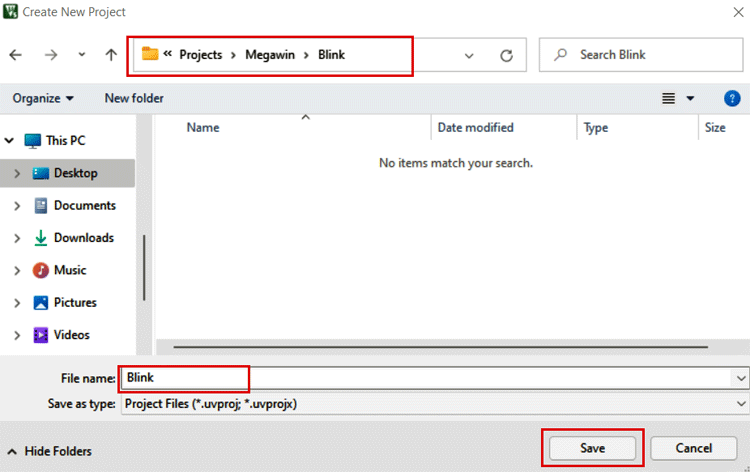
Now open the previously created folder and name the project and click Save as shown below
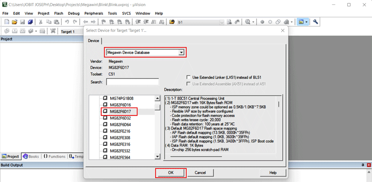
Select the MG82F6D17 from the list and click Ok.
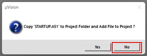
Click on No if prompted to copy the ‘STARTUP.A51’ file
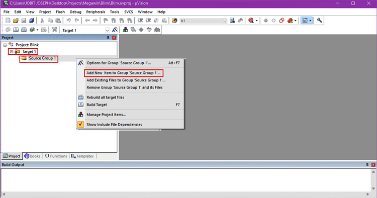
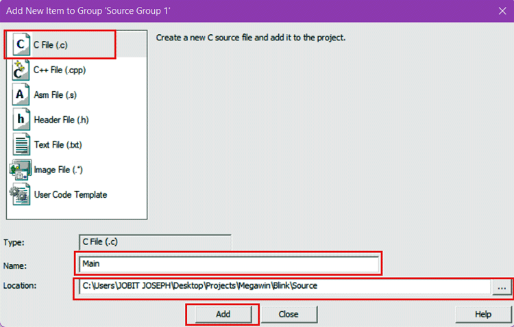
Now in the µVison window in Target -> Source Group 1, right-click on Source group 1 and select Add new item to Group Source Group 1
In the new window select C file, name the file as Main and select the Source folder we have created earlier and click on Add
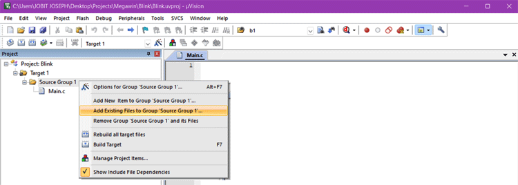
Again, in the project window right click on Source Group 1 and select Add existing files to Source group 1
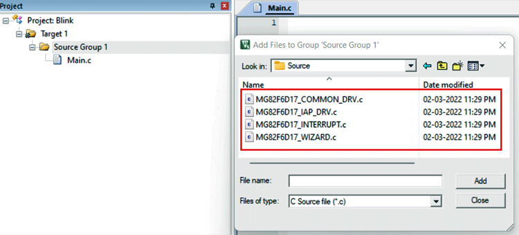
Select the following files from Source/Driver/Source folder and click on add
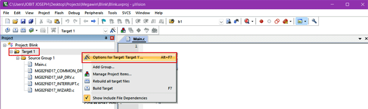
Right-click on Target 1 and select Option for Target ‘Target 1’ or press ALT+F7 to open the options window
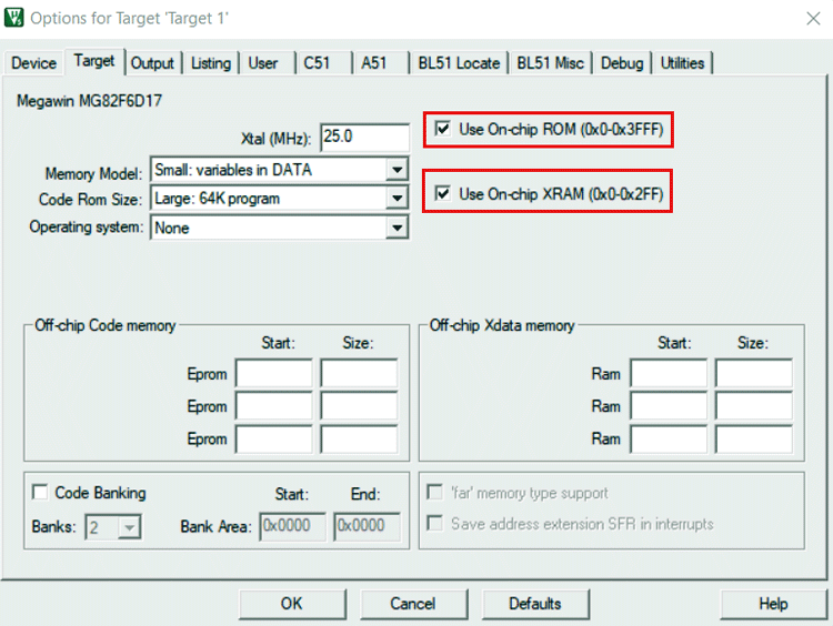
In the options, window tick Use On-chip ROM and Use On-chip XRAM options
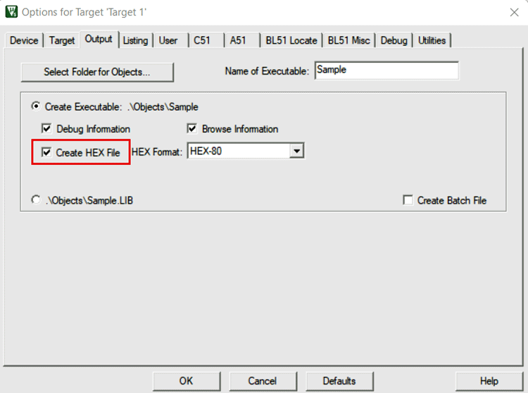
Go to the Output tab and enable Create Hex File option
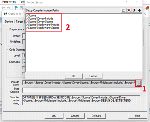
In the C51 tab selects Included paths and add the following folder location
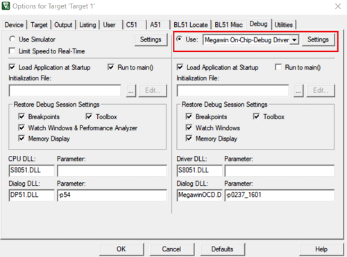
I you want to use the OCD ICE adapter for Debug and programming make the following changes too and press Ok to close the window.
Here is the small animation showing everything briefed above. It will make it easier to understand the procedure.
Schematics for the Blink Example
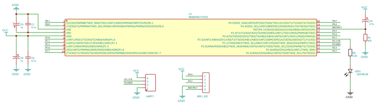
Added a led and current limiting resistor to the Pin P3.3.
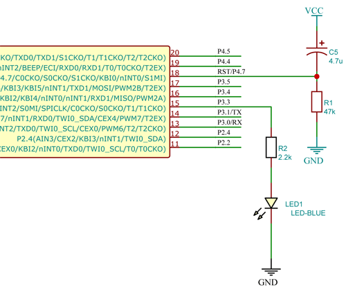
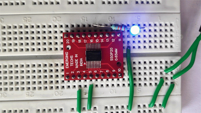
Here is the hardware setup. I used a TSSOP to DIP adapter to use it with the breadboard. As shown in the schematics LED is connected to the pin P3.3 through a 2.2K resistor.
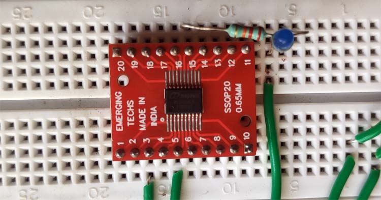
You can follow the circuit given above and make the connections, I have built everything on a breadboard and have also connected my programmer to the microcontroller. The set-up looks like this as shown below.
LED Blinking Program on Megawin MG82F6D17
Now that we have finished setting up the IDE let’s get into the coding. Look at the sample blink code I have shared below
#include "MG82F6D17_CONFIG.h"
#define MCU_SYSCLK      12000000
#define MCU_CPUCLK      (MCU_SYSCLK)
#define LED_Pin     P33
/*************************************************
µS Delay Function
*************************************************/
void DelayXus(u8 xUs)
{
    while(xUs!=0)
    {
#if (MCU_CPUCLK>=11059200)
        _nop_();
#endif
#if (MCU_CPUCLK>=14745600)
        _nop_();
        _nop_();
        _nop_();
        _nop_();
#endif
#if (MCU_CPUCLK>=16000000)
        _nop_();
#endif
#if (MCU_CPUCLK>=22118400)
        _nop_();
        _nop_();
        _nop_();
        _nop_();
        _nop_();
        _nop_();
#endif
#if (MCU_CPUCLK>=24000000)
        _nop_();
        _nop_();
#endif
#if (MCU_CPUCLK>=29491200)
        _nop_();
        _nop_();
        _nop_();
        _nop_();
        _nop_();
        _nop_();
#endif
#if (MCU_CPUCLK>=32000000)
        _nop_();
        _nop_();
#endif
        xUs--;
    }
}
/*************************************************
mS Delay Function
*************************************************/
void DelayXms(u16 xMs)
{
    while(xMs!=0)
    {
        DelayXus(200);
        DelayXus(200);
        DelayXus(200);
        DelayXus(200);
        DelayXus(200);
        xMs--;
    }
}
void main ()
{
    System_Init();
    while(1)
    {
            LED_Pin=!LED_Pin;
            DelayXms(500);
    }
}
Let’s discuss each section of the code-
#include "MG82F6D17_CONFIG.h"
#define MCU_SYSCLK      12000000
#define MCU_CPUCLK      (MCU_SYSCLK)
#define LED_Pin     P33
In the header part, we have added #include "MG82F6D17_CONFIG.h" which will add all the necessary SPLs, header files and all the definitions to the code. And with #define MCU_SYSCLK 12000000, we set the clock frequency to internal 12MHz. This is not the frequency the chip is going to run. This is the frequency of the system oscillator. We will be using the PLL to boost this clock to up to 32MHz as CPU clock or CPU frequency. CPU frequency by the variable MCU_CPUCLK.
Below are the delay functions. The delay functions are rather simple software-based and don’t use any timers. The microsecond delay is generated using some _nop_() instructions. The number of _nop_() depends on the CPU frequency.
/*************************************************
µS Delay Function
*************************************************/
void DelayXus(u8 xUs)
{
    while(xUs!=0)
    {
#if (MCU_CPUCLK>=11059200)
        _nop_();
#endif
#if (MCU_CPUCLK>=14745600)
        _nop_();
        _nop_();
        _nop_();
        _nop_();
#endif
#if (MCU_CPUCLK>=16000000)
        _nop_();
#endif
#if (MCU_CPUCLK>=22118400)
        _nop_();
        _nop_();
        _nop_();
        _nop_();
        _nop_();
        _nop_();
#endif
#if (MCU_CPUCLK>=24000000)
        _nop_();
        _nop_();
#endif
#if (MCU_CPUCLK>=29491200)
        _nop_();
        _nop_();
        _nop_();
        _nop_();
        _nop_();
        _nop_();
#endif
#if (MCU_CPUCLK>=32000000)
        _nop_();
        _nop_();
#endif
        xUs--;
    }
}
Similarly, the millisecond delay function is also software-based and it just calls the microsecond functions thousand times. As these are software-defined delays, the accuracy of these functions is questionable. We will look into it later.
/*************************************************
mS Delay Function
*************************************************/
void DelayXms(u16 xMs)
{
    while(xMs!=0)
    {
        DelayXus(200);
        DelayXus(200);
        DelayXus(200);
        DelayXus(200);
        DelayXus(200);
        xMs--;
    }
}
Let’s look into the main loop. As you can see there are only a few lines of code here. That’s because we are using the MG82F6D17 Driver or SPL which does the most work for us. The System_Init() function is called at the start. Which is defined in the MG82F6D17 Driver and it initialises all the required system registers. Then we are moving to the main loop inside the while(1) loop. The workflow is very simple. Invert the pin status -> wait for 500ms -> repeat the steps. That’s it, Coding can’t be any more simple than this. In this tutorial, we haven’t done any registry level programming. We will be doing that in the very next example.
void main (){
    System_Init();
    while(1) {
            LED_Pin=!LED_Pin;
            DelayXms(500);
    }
}
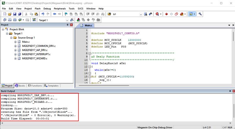
Now let’s compile the program and see if there are any errors. For that click on Build Target from the Project menu or simply press the F7 key. If there are no errors the IDE will compile the code and generate the HEX file which can be found in the Object folder within the project folder.
Uploading Code to Megawin Microcontroller
As we have already established there are multiple ways to upload the code to the MG82F6D17. Through OCD ICE or ISP Programmer or through UART. We will be showing two methods that include using OCD ICE and UART.
Using OCD ICE Adapter
First to uploading using OCD ICE, connect the OCD pins of the microcontroller to the OCD ICE adapter as shown below-
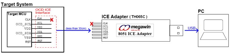
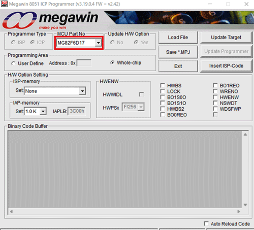
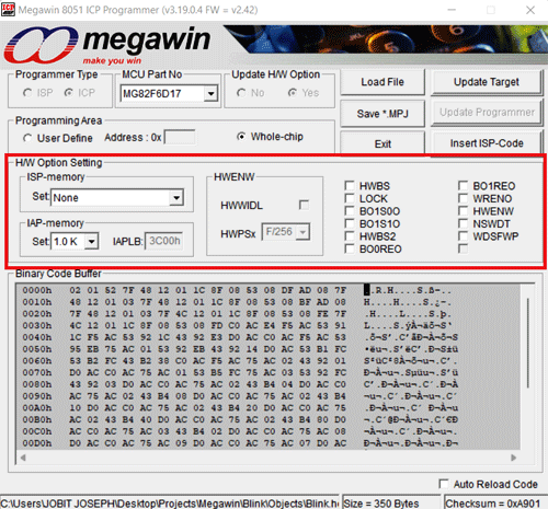
For MG82F6D17, we will only be using five lines including the VDD and GND. The CLK pin is not used in this case. To open the programmer UI, you can run ICPProgremmer.exe directly from the Database Installer folder from (EN)8051_OCD_ICE_For_Keil_v3.19.0.4.zip file or from the Keil installation directory (for me it was C:\Keil_v5\C51\INC\Megawin\ ICPProgrammer.exe). Select the Correct MCU Part Number
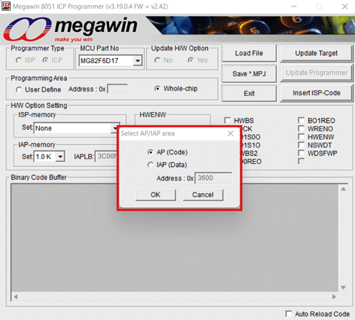
Click “Load File” and choose loading AP(Code) or IAP(Data). “Load File” can be clicked repeatedly to load different files. While loading IAP(Data), users have to key in Address. HEX and BIN data formats are supported for file loading.
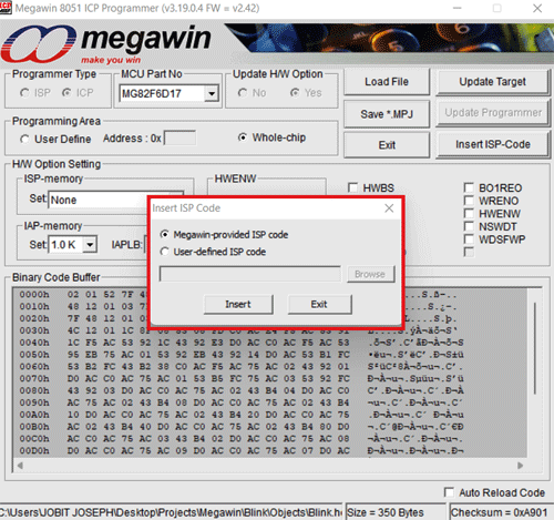
Click “Insert ISP-Code” may choose to insert Megawin-provided ISP code or User-defined ISP code. If the ISP function is not needed, this step can be omitted.
H/W Option Setting let you configure ISP memory, IAP memory and fuse bits. Click on Update target to upload the firmware.
Using UART – USB to TTL Board
For this Connect the USB to TTL converter to the MCU, download the Megawin Com Port ISP file from the given link and open the exe file. Once it is opened select the correct part number and port number.
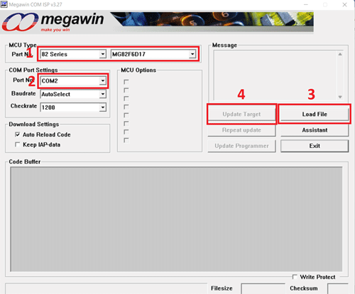
Click on Load file to select the hex file and click on Update target to Load the firmware to the MCU. And once you click on Update Target connect remove and reconnect the VDD to the chip. It will give you a success message indicating uploading is completed.
And here is the result. The LED is blinking at a constant rate of 2Hz, i.e. with a delay of 500ms. A 2.2K resistor is used as a current limit resistor to protect the LED.
#include "MG82F6D17_CONFIG.h"
#define MCU_SYSCLK 12000000
#define MCU_CPUCLK (MCU_SYSCLK)
#define LED_Pin P33
/*************************************************
µS Dealy Function
*************************************************/
void DelayXus(u8 xUs)
{
while(xUs!=0)
{
#if (MCU_CPUCLK>=11059200)
_nop_();
#endif
#if (MCU_CPUCLK>=14745600)
_nop_();
_nop_();
_nop_();
_nop_();
#endif
#if (MCU_CPUCLK>=16000000)
_nop_();
#endif
#if (MCU_CPUCLK>=22118400)
_nop_();
_nop_();
_nop_();
_nop_();
_nop_();
_nop_();
#endif
#if (MCU_CPUCLK>=24000000)
_nop_();
_nop_();
#endif
#if (MCU_CPUCLK>=29491200)
_nop_();
_nop_();
_nop_();
_nop_();
_nop_();
_nop_();
#endif
#if (MCU_CPUCLK>=32000000)
_nop_();
_nop_();
#endif
xUs--;
}
}
/*************************************************
mS Delay Function
*************************************************/
void DelayXms(u16 xMs)
{
while(xMs!=0)
{
DelayXus(200);
DelayXus(200);
DelayXus(200);
DelayXus(200);
DelayXus(200);
xMs--;
}
}
void main ()
{
System_Init();
while(1)
{
LED_Pin=!LED_Pin;
DelayXms(500);
}
}


