Now days finding parking in busy areas is very hard and there is no system to get the details of parking availability online. Imagine if you can get the parking slot availability information on your phone and you don’t have roaming around to check the availability. This problem can be solved by the IoT based smart parking system. Using the IoT based parking system you can easily access the parking slot availability over the internet. This system can completely automate the car parking system. From your entry to the payment and exit all can be done automatically.
So here we are building an IOT based Car Parking System using NodeMCU, five IR sensors, and two servo motors. Two IR sensors are used at entry and exit gate to detect the car while three IR sensors are used to detect the parking slot availability. Servo motors are used to open and close the gates according to the sensor value. Here we are using the Adafruit IO platform to show publish the data on cloud which can be monitored from anywhere in the world.
Components Required
Hardware
- NodeMCU ESP8266
- IR Sensor (5)
- Servo Motor (2)
Online Services
- Adafruit IO
Circuit Diagram
The circuit diagram for this IoT based smart parking system project is given below.
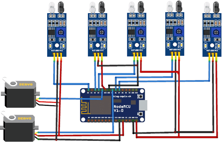
In this Smart Parking System using IOT, we are using five IR Sensors and two servo motors. IR sensors and Servo motors are connected to the NodeMCU. NodeMCU controls the complete process and sends the parking availability and parking time information to Adafruit IO so that it can be monitored from anywhere in the world using this platform. Two IR sensors are used at entry and exit gate so that it can detect the cars at entry and exit gate and automatically open and close the gate. We previously used Adafruit IO cloud in many IoT projects, follow the link to learn more.
Two servo motors are used as entry and exit gate, so whenever the IR sensor detects a car, the servo motor automatically rotates from 45° to 140°, and after a delay, it will return to its initial position. Another three IR sensors are used to detect if the parking slot is available or occupied and send the data to NodeMCU. Adafruit IO dashboard also has two buttons to manually operate the entry and exit gate.
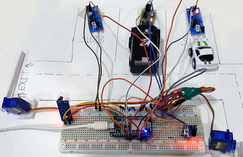
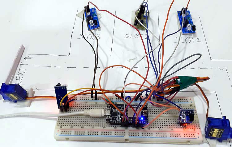
This is how this complete setup for Smart Parking System using IOT will look:
Adafruit IO Setup for IOT Parking System
Adafruit IO is an open data platform that allows you to aggregate, visualize, and analyze live data on the cloud. Using Adafruit IO, you can upload, display, and monitor your data over the internet, and make your project IoT enabled. You can control motors, read sensor data, and make cool IoT applications over the internet using Adafruit IO. For test and try, with some limitation, Adafruit IO is free to use. We have also used Adafruit IO with Raspberry Pi previously.
1. To use Adafruit IO, first, you have to create an account on Adafruit IO. To do this, go to the Adafruit IO website and click on ‘Get started for Free’ on the top right of the screen.

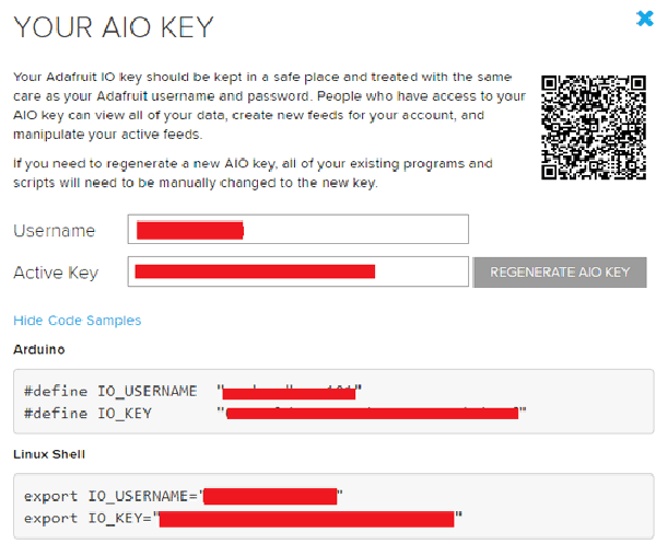
2. After finishing the account creation process, log in to your account and click on ‘AIO Key’ on the top right corner to get your account username and AIO key.

When you click on ‘AIO Key,’ a window will pop up with your Adafruit IO AIO Key and username. Copy this key and username, it will be needed later in the code.
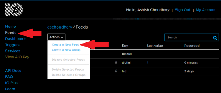
3. Now, after this, you need to create a feed. To create a feed, click on ‘Feed.’ Then click on ‘Actions,’ and then on ‘Create a New Feed’ as shown in the image below.
4. After this, a new window will open to enter the Name and Description of the feed. The writing description is optional.
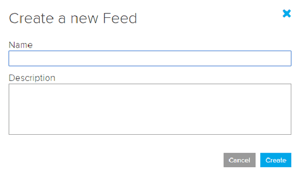
5. Click on ‘Create,’ after this; you will be redirected to your newly created feed.
For this project, we created a total of nine feeds for exit gate, entry gate, slot 1 entry & exit, slot 2 entry & exit, and slot 3 entry & exit.
After creating feeds, now create an Adafruit IO dashboard to show all of these feeds on a single page. To create a dashboard, click on the Dashboard option and then click on the ‘Action,’ and after this, click on ‘Create a New Dashboard.’
In the next window, enter the name for your dashboard and click on ‘Create.’
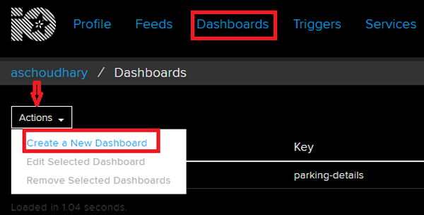
6. As the dashboard is created now, we will add our feeds to the dashboard. To add a feed, click on the ‘+’ in the top right corner.
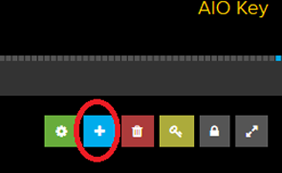
First, we will add two RESET buttons blocks for Entry and Exit gate and then seven TEXT blocks for parking details.
To add a button on the dashboard click on the RESET block.
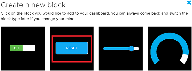
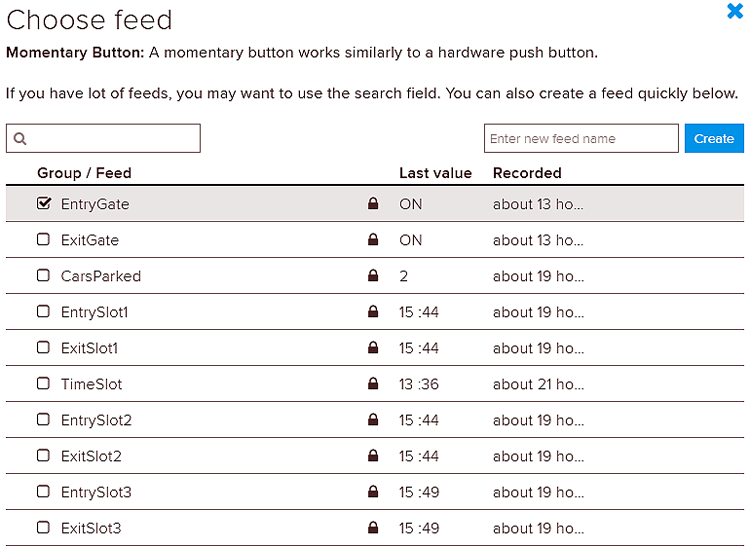
In the next window it will ask you to choose the feed, so click on the entry gate feed.
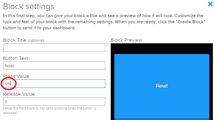
In this final step, give your block a title and customize it accordingly. Change the press value from ‘1’ to ‘ON’. So whenever the button is pressed it will send the ‘ON’ string to NodeMCU, and NodeMCU will perform the further task. If you don’t want to change the press value here than you can change the condition in the program.
After this, follow the same procedure to create another block for the exit gate.
To create the rest of the blocks follow the same procedure, but instead of creating a RESET block, create a TEXT block so that you can show the parking details.
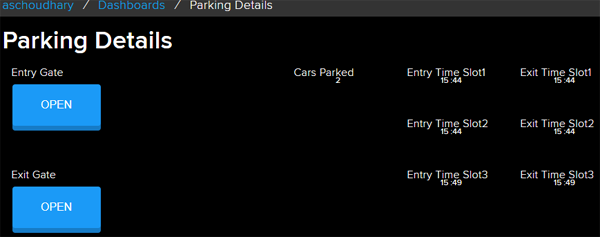
After creating all the blocks, my dashboard looks like below. You can edit the dashboard by clicking on the settings buttons

Programming NodeMCU for IOT Parking System
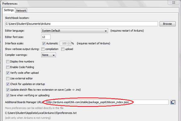
To program NodeMCU with Arduino IDE go to File–>Perferences–>Settings.
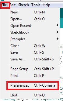
Enter https:// arduino.esp8266.com/stable/package_esp8266com_index.json into the ‘Additional Board Manager URL’ field and click ‘Ok’.
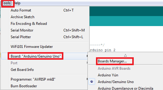
Now go to Tools > Board > Boards Manager.
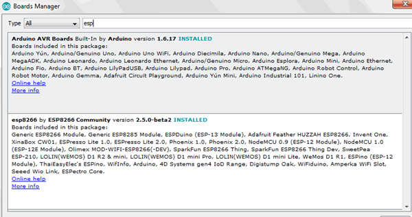
In Boards Manager window, Type esp in the search box, esp8266 will be listed there below. Now select the latest version of the board and click on install.
After installation is complete, go to Tools >Board >and select NodeMCU 1.0(ESP-12E Module). Now you can program NodeMCU with Arduino IDE.
Complete code for this Smart Parking System using IOT is given at the end of this tutorial, here we are explaining the program step by step so that you can easily understand the working of this code.
First, include all the required libraries. ESP8266 Wi-Fi and Servo.h libraries are already installed in the IDE. You can download the NTP client and Adafruit MQTT libraries from the below links:
#include <ESP8266WiFi.h>
#include <Servo.h>
#include <NTPClient.h>
#include <WiFiUdp.h>
#include <NTPClient.h>;
#include <WiFiUdp.h>
#include "Adafruit_MQTT.h"
#include "Adafruit_MQTT_Client.h"
Then include the Wi-Fi and Adafruit IO credentials that you copied from the Adafruit IO server. These will include the MQTT server, Port No, User Name and AIO Key
const char *ssid =  "WiFi Name";     // Enter your WiFi Name
const char *pass =  "Password"; // Enter your WiFi Password
String time1= "89";
#define MQTT_SERV "io.adafruit.com"
#define MQTT_PORT 1883
#define MQTT_NAME "User Name"
#define MQTT_PASS "AIO Key"
Set up the feed you're publishing to. Here Agriculture Data is the feed name.
Adafruit_MQTT_Subscribe EntryGate = Adafruit_MQTT_Subscribe(&mqtt, MQTT_NAME "/f/EntryGate");
Adafruit_MQTT_Subscribe ExitGate = Adafruit_MQTT_Subscribe(&mqtt, MQTT_NAME "/f/ExitGate");
…………………………………………..
…………………………………………..
Connect the Entry and Exit Servo Motor to the D4, D5 Pins of the NodeMCU, and select the out pins of IR sensor as INPUT.
  myservo.attach(D4);
  myservos.attach(D5);
  pinMode(carExited, INPUT);
  pinMode(carEnter, INPUT);
  pinMode(slot1, INPUT);
  pinMode(slot2, INPUT);
  pinMode(slot3, INPUT);
Inside the void loop, timeClient.update() function is used to update the date and time whenever we request to NTP servers. After getting the data, we store the hour, minute and second in three different integers.
timeClient.update();
 hh = timeClient.getHours();
 mm = timeClient.getMinutes();
 ss = timeClient.getSeconds();
Digitally read the entry and exit IR sensor pins and check if these pins are high. If pins are high, then move the servo motor to open the entry and exit gate. Then increase the count for entry gate and decrease the count for exit gate and publish the data to the Adafruit IO dashboard.
if (entrysensor == 1) {                     // if high then count and send data
   count=  count+1;                             //increment count
   myservos.write(OPEN_ANGLE);
   delay(3000);
   myservos.write(CLOSE_ANGLE);
   }
   if (exitsensor == 1) {                            //if high then count and send
   count= count-1;                                    //decrement count
   myservo.write(OPEN_ANGLE);
   delay(3000);
   myservo.write(CLOSE_ANGLE);
  }
  if (! CarsParked.publish(count)) {}
Check the slot 1 IR sensor. If it is ‘1’ and Boolean function is false, then get the entry time from the NTP server and save it in EntryTimeSlot1 variable. Publish the variable data to the Adafruit IO feed.
if (s1 == 1 && s1_occupied == false) {
        EntryTimeSlot1 =  h +" :" + m;
        s1_occupied = true;
        if (! EntrySlot1.publish ((char*) EntryTimeSlot1.c_str())){}
    }
If the IR sensor pin change to zero and Boolean function is true then publish the exit time to Adafruit IO feed.
if(s1 == 0 && s1_occupied == true) {
       ExitTimeSlot1 =  h +" :" + m;
       s1_occupied = false;
        if (! ExitSlot1.publish((char*) ExitTimeSlot1.c_str())){}
    }
Do similar steps as above for slot2 and slot 3 sensors.
if (s2 == 1&& s2_occupied == false) {
      EntryTimeSlot2 =  h +" :" + m;
      s2_occupied = true;
      if (! EntrySlot2.publish((char*) EntryTimeSlot2.c_str())){}
    }
  if(s2 == 0 && s2_occupied == true) {
       ExitTimeSlot2 =  h +" :" + m;
        s2_occupied = false;
        if (! ExitSlot2.publish((char*) ExitTimeSlot2.c_str())){}
  }
  if (s3 == 1&& s3_occupied == false) {
       EntryTimeSlot3 =  h +" :" + m;
      s3_occupied = true;
       if (! EntrySlot3.publish((char*) EntryTimeSlot3.c_str())){}
    }
  if(s3 == 0 && s3_occupied == true) {
        ExitTimeSlot3 =  h +" :" + m;
       s3_occupied = false;
        if (! ExitSlot3.publish((char*) ExitTimeSlot3.c_str())){ }
  }
Here we are directly checking for a specific word in our subscribed feed, and if the word matches with our specified word, i.e., ‘ON,’ it will rotate the servo motor to open the gate.
if (subscription == &EntryGate)
     {
      Serial.println((char*) EntryGate.lastread);
   if (!strcmp((char*) EntryGate.lastread, "ON"))
      {
       myservos.write(OPEN_ANGLE);
       delay(3000);
       myservos.write(CLOSE_ANGLE);
    }
Do similar steps as above for the Exit gate.
This is how the parking details are published on the Adafruit IO dashboard. It will show the entry time and exit time for every slot. This dashboard also has two buttons to manually open the entry and exit gate.
So this is how a Smart Parking System using IoT can be built. You can add more sensors to increase the parking slots and can also add a payment system to automatically pay the parking fee. Comment below if you have any doubts regarding this project.
#include <ESP8266WiFi.h>
#include <Servo.h>
#include <NTPClient.h>
#include <WiFiUdp.h>
#include <NTPClient.h>;
#include <WiFiUdp.h>
#include "Adafruit_MQTT.h"
#include "Adafruit_MQTT_Client.h"
const char *ssid = "Galaxy-M20"; // Enter your WiFi Name
const char *pass = "ac312124"; // Enter your WiFi Password
#define MQTT_SERV "io.adafruit.com"
#define MQTT_PORT 1883
#define MQTT_NAME "aschoudhary"
#define MQTT_PASS "1ac95cb8580b4271bbb6d9f75d0668f1"
WiFiUDP ntpUDP;
NTPClient timeClient(ntpUDP, "pool.ntp.org", 19800,60000);
Servo myservo; //servo as gate
Servo myservos; //servo as gate
int carEnter = D0; // entry sensor
int carExited = D2; //exi sensor
int slot3 = D7;
int slot2 = D6;
int slot1 = D3;
int count =0;
int CLOSE_ANGLE = 80; // The closing angle of the servo motor arm
int OPEN_ANGLE = 0; // The opening angle of the servo motor arm
int hh, mm, ss;
int pos;
int pos1;
String h, m,EntryTimeSlot1,ExitTimeSlot1, EntryTimeSlot2,ExitTimeSlot2, EntryTimeSlot3,ExitTimeSlot3;
boolean entrysensor, exitsensor,s1,s2,s3;
boolean s1_occupied = false;
boolean s2_occupied = false;
boolean s3_occupied = false;
WiFiClient client;
Adafruit_MQTT_Client mqtt(&client, MQTT_SERV, MQTT_PORT, MQTT_NAME, MQTT_PASS);
//Set up the feed you're subscribing to
Adafruit_MQTT_Subscribe EntryGate = Adafruit_MQTT_Subscribe(&mqtt, MQTT_NAME "/f/EntryGate");
Adafruit_MQTT_Subscribe ExitGate = Adafruit_MQTT_Subscribe(&mqtt, MQTT_NAME "/f/ExitGate");
//Set up the feed you're publishing to
Adafruit_MQTT_Publish CarsParked = Adafruit_MQTT_Publish(&mqtt,MQTT_NAME "/f/CarsParked");
Adafruit_MQTT_Publish EntrySlot1 = Adafruit_MQTT_Publish(&mqtt,MQTT_NAME "/f/EntrySlot1");
Adafruit_MQTT_Publish ExitSlot1 = Adafruit_MQTT_Publish(&mqtt,MQTT_NAME "/f/ExitSlot1");
Adafruit_MQTT_Publish EntrySlot2 = Adafruit_MQTT_Publish(&mqtt,MQTT_NAME "/f/EntrySlot2");
Adafruit_MQTT_Publish ExitSlot2 = Adafruit_MQTT_Publish(&mqtt,MQTT_NAME "/f/ExitSlot2");
Adafruit_MQTT_Publish EntrySlot3 = Adafruit_MQTT_Publish(&mqtt,MQTT_NAME "/f/EntrySlot3");
Adafruit_MQTT_Publish ExitSlot3 = Adafruit_MQTT_Publish(&mqtt,MQTT_NAME "/f/ExitSlot3");
void setup() {
delay(1000);
Serial.begin (9600);
mqtt.subscribe(&EntryGate);
mqtt.subscribe(&ExitGate);
timeClient.begin();
myservo.attach(D4); // servo pin to D6
myservos.attach(D5); // servo pin to D5
pinMode(carExited, INPUT); // ir as input
pinMode(carEnter, INPUT); // ir as input
pinMode(slot1, INPUT);
pinMode(slot2, INPUT);
pinMode(slot3, INPUT);
WiFi.begin(ssid, pass); //try to connect with wifi
Serial.print("Connecting to ");
Serial.print(ssid); // display ssid
while (WiFi.status() != WL_CONNECTED) {
Serial.print("."); // if not connected print this
delay(500);
}
Serial.println();
Serial.print("Connected to ");
Serial.println(ssid);
Serial.print("IP Address is : ");
Serial.println(WiFi.localIP()); //print local IP address
}
void loop() {
MQTT_connect();
timeClient.update();
hh = timeClient.getHours();
mm = timeClient.getMinutes();
ss = timeClient.getSeconds();
h= String(hh);
m= String(mm);
h +" :" + m;
entrysensor= !digitalRead(carEnter);
exitsensor = !digitalRead(carExited);
s1 = digitalRead(slot1);
s2 = digitalRead(slot2);
s3 = digitalRead(slot3);
if (entrysensor == 1) { // if high then count and send data
count= count+1; //increment count
myservos.write(OPEN_ANGLE);
delay(3000);
myservos.write(CLOSE_ANGLE);
}
if (exitsensor == 1) { //if high then count and send
count= count-1; //decrement count
myservo.write(OPEN_ANGLE);
delay(3000);
myservo.write(CLOSE_ANGLE);
}
if (! CarsParked.publish(count)) {}
if (s1 == 1 && s1_occupied == false) {
Serial.println("Occupied1 ");
EntryTimeSlot1 = h +" :" + m;
//Serial.print("EntryTimeSlot1");
//Serial.print(EntryTimeSlot1);
s1_occupied = true;
if (! EntrySlot1.publish((char*) EntryTimeSlot1.c_str())){}
}
if(s1 == 0 && s1_occupied == true) {
Serial.println("Available1 ");
ExitTimeSlot1 = h +" :" + m;
//Serial.print("ExitTimeSlot1");
//Serial.print(ExitTimeSlot1);
s1_occupied = false;
if (! ExitSlot1.publish((char*) ExitTimeSlot1.c_str())){}
}
if (s2 == 1&& s2_occupied == false) {
Serial.println("Occupied2 ");
EntryTimeSlot2 = h +" :" + m;
//Serial.print("EntryTimeSlot2");
//Serial.print(EntryTimeSlot2);
s2_occupied = true;
if (! EntrySlot2.publish((char*) EntryTimeSlot2.c_str())){}
}
if(s2 == 0 && s2_occupied == true) {
Serial.println("Available2 ");
ExitTimeSlot2 = h +" :" + m;
//Serial.print("ExitTimeSlot2");
//Serial.print(ExitTimeSlot2);
s2_occupied = false;
if (! ExitSlot2.publish((char*) ExitTimeSlot2.c_str())){}
}
if (s3 == 1&& s3_occupied == false) {
Serial.println("Occupied3 ");
EntryTimeSlot3 = h +" :" + m;
//Serial.print("EntryTimeSlot3: ");
//Serial.print(EntryTimeSlot3);
s3_occupied = true;
if (! EntrySlot3.publish((char*) EntryTimeSlot3.c_str())){}
}
if(s3 == 0 && s3_occupied == true) {
Serial.println("Available3 ");
ExitTimeSlot3 = h +" :" + m;
//Serial.print("ExitTimeSlot3: ");
//Serial.print(ExitTimeSlot3);
s3_occupied = false;
if (! ExitSlot3.publish((char*) ExitTimeSlot3.c_str())){ }
}
Adafruit_MQTT_Subscribe * subscription;
while ((subscription = mqtt.readSubscription(5000)))
{
if (subscription == &EntryGate)
{
//Print the new value to the serial monitor
Serial.println((char*) EntryGate.lastread);
if (!strcmp((char*) EntryGate.lastread, "ON"))
{
myservos.write(OPEN_ANGLE);
delay(3000);
myservos.write(CLOSE_ANGLE);
}
}
if (subscription == &ExitGate)
{
//Print the new value to the serial monitor
Serial.println((char*) EntryGate.lastread);
if (!strcmp((char*) ExitGate.lastread, "ON"))
{
myservo.write(OPEN_ANGLE);
delay(3000);
myservo.write(CLOSE_ANGLE);
}
}
}
}
void MQTT_connect()
{
int8_t ret;
// Stop if already connected.
if (mqtt.connected())
{
return;
}
uint8_t retries = 3;
while ((ret = mqtt.connect()) != 0) // connect will return 0 for connected
{
mqtt.disconnect();
delay(5000); // wait 5 seconds
retries--;
if (retries == 0)
{
// basically die and wait for WDT to reset me
while (1);
}
}
}


