Manhole monitoring is an important aspect of municipal infrastructure as accidents due to broken and missing manhole covers are quite frequent. Poor management and monitoring of the Manholes can also cause urban floods which are most common in crowded cities. This problem can be addressed by using a Manhole Management Device based on IoT and Sensor Technology.
In this article, we are going to build an IoT-based Manhole Monitoring device. This device includes a gas sensor to monitor the gas presence in Manhole so that toxicity can be monitored, an ultrasonic sensor to detect the water level, and a tilt sensor to indicate whether the manhole cover is tilted. If any of these values go beyond the predefined values then we send an SMS to an authority number using the SIM800l GSM Module. This complete setup will be powered using a 18650 cell.
Components Required
- NodeMCU
- SIM800L GSM Module
- XL6009 Booster Module
- MQ Gas Sensor
- KY-017 Mercury Tilt Switch Module
- JSN SR-04T Waterproof Ultrasonic Sensor
- 18650 Cell & Cell Holder
Manhole Monitoring System Circuit Diagram
The complete schematic for the IoT Based Manhole Monitoring System is given below:
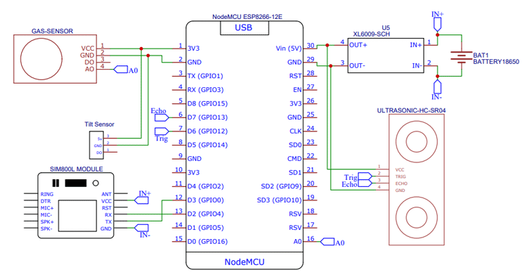
This circuit isn’t that hard. Here we have used three sensors i.e., Gas Sensor, Ultrasonic Sensor, and Tilt Sensor, one XL6009 Booster Module, SIM800L GSM Module, and 18650 cells. XL6009 Booster Module is used to boost the voltage from 18650 to 5V, Gas sensor is used to detect the presence of Gas. The Ultrasonic Sensor is used to detect the water level and the Tilt sensor is used to detect whether the cover of the manhole is tilted or not. Finally, a SIM800L GSM Module is used to send SMS notifications about these events.
Manhole Monitoring System Code
Now after connecting the components, it’s time to program the NodeMCU to read the sensor data and send the message updates about the changes in sensor readings. The complete code for the same is given at the end of the document. Here we are explaining some important parts of the code.
The code starts by including the SoftwareSerial library and defining the NodeMCU pins connected to the sensor and GSM module.
#include <SoftwareSerial.h>
#define sensor D5
#define ECHOPIN D7
#define TRIGPIN D6
int sensorPin = A0;
SoftwareSerial mySerial(D3, D2);
Then inside the setup() function, define the trigger pin as an output, the echo pin of ultrasonic sensor, and signal pin of tilt sensor as an Input and also start the serial communication at 9600 for showing the results on the serial monitor.
Serial.begin(9600);
pinMode(sensor, INPUT);
pinMode(ECHOPIN,INPUT_PULLUP);
pinMode(TRIGPIN, OUTPUT);
digitalWrite(ECHOPIN, HIGH);
mySerial.begin(9600);
In the loop, first, we are reading the Tilt sensor and Gas sensor readings using digitalRead() and analogRead() functions and then to measure the distance using ultrasonic sensor, first set trigger pin to LOW State for 2 µs to make sure that the trigger pin is clear. Then set the trigger pin high for 15 us to send an ultrasonic wave. We will use the pulseIn() function to read the travel time and store that value into the variable “duration”. In the end, we will print the value of the distance on the Serial Monitor.
int readings = digitalRead(sensor);
int val = analogRead(A0);
digitalWrite(TRIGPIN, LOW);
delayMicroseconds(2);
digitalWrite(TRIGPIN, HIGH);
delayMicroseconds(15);
digitalWrite(TRIGPIN, LOW);
int distance1 = pulseIn(ECHOPIN, HIGH, 26000);
int distance=distance1/58;
Serial.println(distance);
Serial.println("   cm");
delay(500);
Then in last, we are comparing these readings and if the readings exceed a predefined value, then we will use the GSM module to send the SMS notifications. The AT commands to send messages are explained below:
AT+CMGF=1 – Used to select message format as text. By default, the format is Protocol Data Unit (PDU)
AT+CMGS=+ZZxxxxxxxxxx – This command with the phone number specified sends an SMS message to a GSM phone.
mySerial.println("AT"); //Once the handshake test is successful, it will back to OK
updateSerial();
mySerial.println("AT+CMGF=1"); // Configuring TEXT mode
updateSerial();
mySerial.println("AT+CMGS=\"+919829559608\"");
updateSerial();
mySerial.print("Tilt Detected"); //text content
updateSerial();
mySerial.write(26);
Building the Circuit on Perf-board
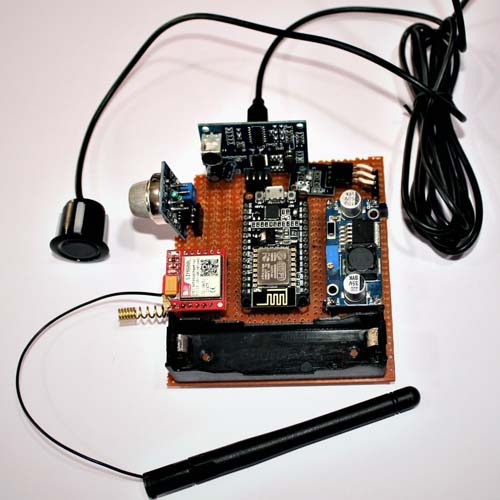
After testing the circuit on the breadboard and making sure that everything works fine, I proceeded with building the circuit on perf-board to make it more application friendly. The soldered board looks like below:
Testing the Manhole Monitoring System
Now as everything is ready, let's test the setup. For testing, I filled the bucket with water and used the sunboard as a cover for the bucket. Then I mounted the hardware on the cover as shown below:
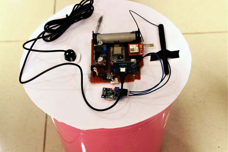
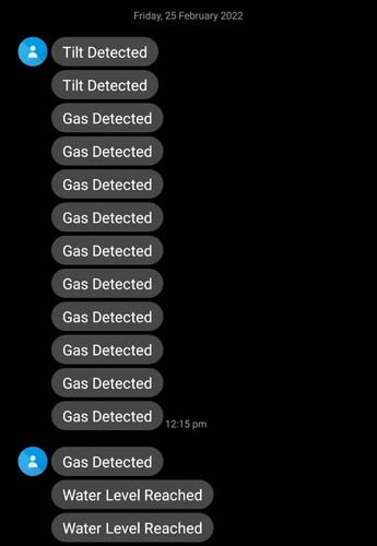
Initially, the bucket is empty and the cover is perfectly balanced but when we tilt the cover, the tilt sensor detects the movement and sends a message. Similarly, we tested the Gas sensor and Water level and it worked as expected.
The complete working for this project can be found in the video below, if you have any questions, you can leave them in the comment section below.
#include <SoftwareSerial.h>
#define sensor D5
#define ECHOPIN D7
#define TRIGPIN D6
int sensorPin = A0;
//Create software serial object to communicate with SIM800L
SoftwareSerial mySerial(D3, D2); //SIM800L Tx & Rx is connected to Arduino #3 & #2
void setup()
{
//Begin serial communication with Arduino and Arduino IDE (Serial Monitor)
Serial.begin(9600);
pinMode(sensor, INPUT);
pinMode(ECHOPIN,INPUT_PULLUP);
pinMode(TRIGPIN, OUTPUT);
digitalWrite(ECHOPIN, HIGH);
//Begin serial communication with Arduino and SIM800L
mySerial.begin(9600);
delay(1000);
}
void loop()
{
int readings = digitalRead(sensor);
int val = analogRead(A0);
//Serial.println(IR_readings);
digitalWrite(TRIGPIN, LOW);
delayMicroseconds(2);
digitalWrite(TRIGPIN, HIGH);
delayMicroseconds(15);
digitalWrite(TRIGPIN, LOW);
int distance1 = pulseIn(ECHOPIN, HIGH, 26000);
int distance=distance1/58;
Serial.println(distance);
Serial.println(" cm");
delay(500);
if (readings == 1 )
{
//Serial.print("Tilt Detected");
mySerial.println("AT"); //Once the handshake test is successful, it will back to OK
updateSerial();
mySerial.println("AT+CMGF=1"); // Configuring TEXT mode
updateSerial();
mySerial.println("AT+CMGS=\"+zzxxxxxxxxxxx\"");//change ZZ with country code and xxxxxxxxxxx with phone number to sms
updateSerial();
mySerial.print("Tilt Detected"); //text content
updateSerial();
mySerial.write(26);
}
if (distance <= 20)
{
Serial.print("Water Level");
mySerial.println("AT"); //Once the handshake test is successful, it will back to OK
updateSerial();
mySerial.println("AT+CMGF=1"); // Configuring TEXT mode
updateSerial();
mySerial.println("AT+CMGS=\"+919829559608\"");//change ZZ with country code and xxxxxxxxxxx with phone number to sms
updateSerial();
mySerial.print("Water Level Reached"); //text content
updateSerial();
mySerial.write(26);
}
if (val > 80 )
{
Serial.print("Gas Detected");
mySerial.println("AT"); //Once the handshake test is successful, it will back to OK
updateSerial();
mySerial.println("AT+CMGF=1"); // Configuring TEXT mode
updateSerial();
mySerial.println("AT+CMGS=\"+919829559608\"");//change ZZ with country code and xxxxxxxxxxx with phone number to sms
updateSerial();
mySerial.print("Gas Detected"); //text content
updateSerial();
mySerial.write(26);
}
delay(1000);
}
void updateSerial()
{
delay(500);
while (Serial.available())
{
mySerial.write(Serial.read());//Forward what Serial received to Software Serial Port
}
while(mySerial.available())
{
Serial.write(mySerial.read());//Forward what Software Serial received to Serial Port
}
}