


Farmers across the world face a lot of difficulties in growing crops because of unpredictable weather conditions and shortage of water. The traditional irrigation system uses a large amount of water and supplies uneven water to corps. This affects the quality of crops.
Many farmers already start using the Greenhouse farming and Smart Irrigation System. Emerging IoT technologies and sensors are used to develop the irrigation system that can automatically supply water according to climate conditions like moisture value, temperature, etc.
In this project, we are building an IoT based smart irrigation System using NodeMCU, Moisture sensor, and LDR. It will automatically sprinkle the water to plants when the moisture value goes below a particular value. It will also send the moisture data to Adafruit IO Server to keep track of the land condition. Adafruit IO dashboard will also have some buttons to manually turn on/off the solenoid valve and lights. This project uses a solenoid valve to supply the water to the plants. You can change the moisture value at which the solenoid valve should turn on according to your plant's requirement. Here we are using NodeMCU ESP8666 which is a very popular Wi-Fi module for IoT based Projects.
Components Required
Hardware
- NodeMCU ESP8266
- Soil Moisture Sensor Module
- LDR
- 10K Pot
- solenoid valve
- Relay Module
- LED
Online Services
- Adafruit IO
Circuit Diagram for Smart Irrigation System using IoT:
Circuit diagram for Smart Irrigation System using IoT is given below:
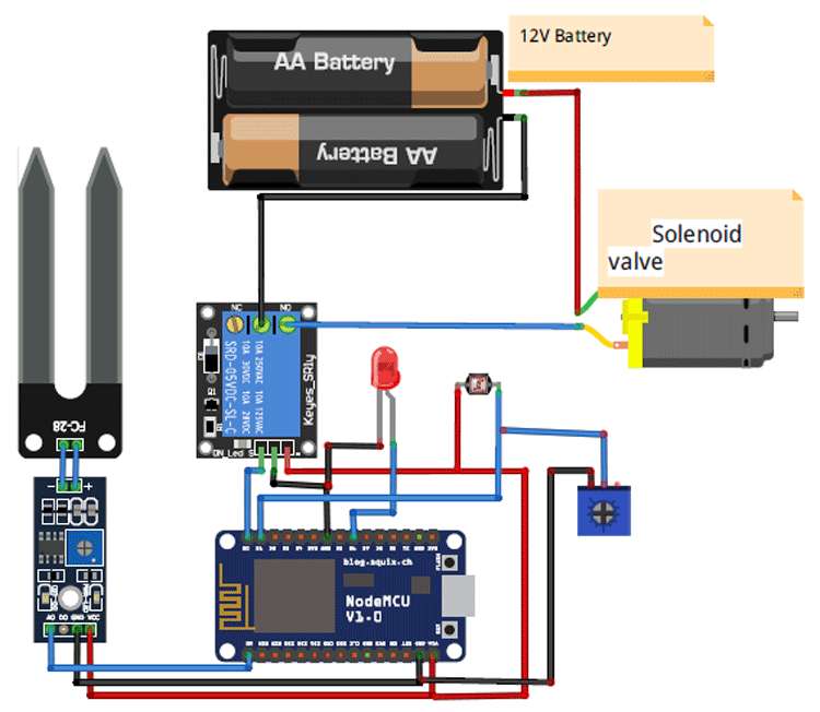
In this circuit, the Soil sensor is connected to the A0 pin of NodeMCU. LDR sensor is connected to the D1 pin, and the Relay module is connected to the D0 pin of NodeMCU. Solenoid Valve is connected to the relay module, so whenever NodeMCU generates trigger it will sprinkle water.
This is how the setup of the IoT based Smart Irrigation System will look:
Adafruit IO Setup
Adafruit IO is an open data platform that allows you to aggregate, visualize, and analyze live data on the cloud. Using Adafruit IO, you can upload, display, and monitor your data over the internet, and make your project IoT enabled. You can control motors, read sensor data, and make cool IoT applications over the internet using Adafruit IO. For test and try, with some limitation, Adafruit IO is free to use. We have also used Adafruit IO with Raspberry Pi previously.
1. To use Adafruit IO, first, you have to create an account on Adafruit IO. To do this, go to the Adafruit IO website and click on ‘Get started for Free’ on the top right of the screen.

2. After finishing the account creation process, log in to your account and click on ‘AIO Key’ on the top right corner to get your account username and AIO key.
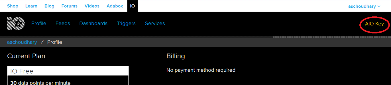
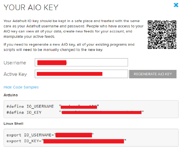
When you click on ‘AIO Key,’ a window will pop up with your Adafruit IO AIO Key and username. Copy this key and username, it will be needed later in the code.
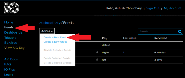
3. Now, after this, you need to create a feed. To create a feed, click on ‘Feed.’ Then click on ‘Actions,’ and then on ‘Create a New Feed’ as shown in the image below.
4. After this, a new window will open to enter the Name and Description of the feed. The writing description is optional.
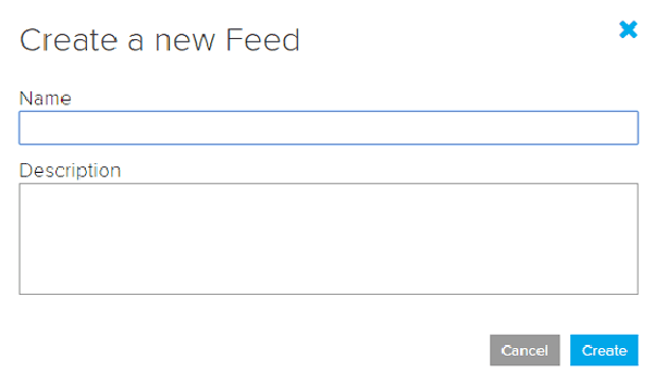
5. Click on ‘Create,’ after this; you will be redirected to your newly created feed.
For this project, we created a total of three feeds- for solenoid valve, moisture data, and LED.
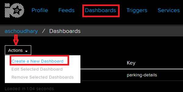
After creating feeds, now create an Adafruit IO dashboard to show all of these feeds on a single page. To create a dashboard, click on the Dashboard option and then click on the ‘Action,’ and after this, click on ‘Create a New Dashboard.’
In the next window, enter the name for your dashboard and click on ‘Create.’
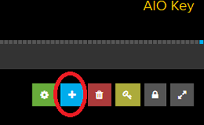
6. As the dashboard is created now, we will add our feeds to the dashboard. To add a feed, click on the ‘+’ in the top right corner.
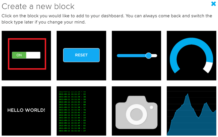
First, we will add two toggle buttons blocks to control the LED and solenoid valves. And then one Graph block for Moisture Data.
To add a button on the dashboard, click on the Toggle block.
In the next window, it will ask you to choose the feed, so click on LED feed.
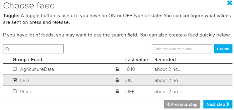
After this, follow the same procedure to create another Toggle button block for the solenoid valve.
7. Now to add the Graph on your dashboard, follow the same procedure, but instead of creating a RESET block, create a Line Chart block for graph view.
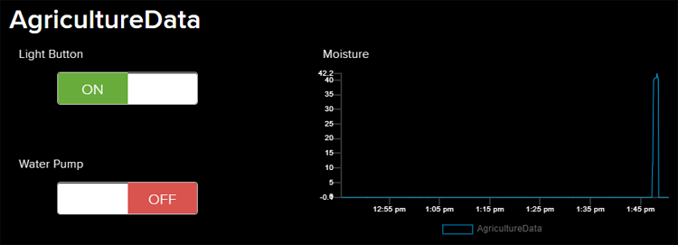
After creating all the blocks, my dashboard looks like this:
You can edit your dashboard by clicking on the settings buttons.
Programming NodeMCU for Smart Irrigation System
To program the NodeMCU for Smart Irrigation System, plug the NodeMCU to your laptop with a Micro USB Cable and open Arduino IDE. In this program, only the Adafruit MQTT library is used as an external library. You can download the library from here:
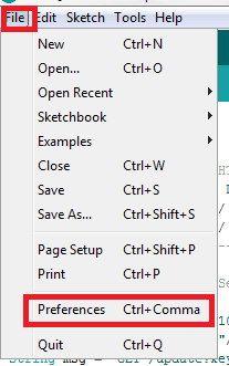
To program NodeMCU with Arduino IDE go to File–>Perferences–>Settings.
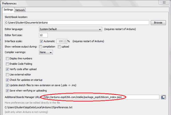
Enter https:// arduino.esp8266.com/stable/package_esp8266com_index.json into the ‘Additional Board Manager URL’ field and click ‘Ok’.
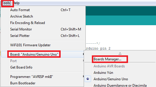
Now go to Tools > Board > Boards Manager.
In Boards Manager window, Type esp in the search box, esp8266 will be listed there below. Now select the latest version of the board and click on install.
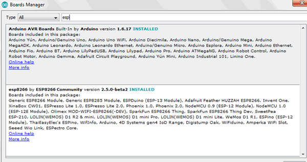
After installation is complete, go to Tools >Board >and select NodeMCU 1.0(ESP-12E Module). Now you can program NodeMCU with Arduino IDE.
Complete code is given at the end of this tutorial, here we are explaining the program step by step so that you can easily understand the working of this code.
Start your code by including all the required libraries.
#include <ESP8266WiFi.h>
#include "Adafruit_MQTT.h"
#include "Adafruit_MQTT_Client.h"
Then include the WiFi and Adafruit IO credentials that you copied from the Adafruit IO server. These will include the MQTT server, Port No, User Name and AIO Key
const char *ssid =  "WiFi Name";     // Enter your WiFi Name
const char *pass =  "Password"; // Enter your WiFi Password
#define MQTT_SERV "io.adafruit.com"
#define MQTT_PORT 1883
#define MQTT_NAME "User Name"
#define MQTT_PASS "AIO Key"
Set up the feed you're publishing to. Here AgricultureData is the feed name.
Adafruit_MQTT_Publish AgricultureData = Adafruit_MQTT_Publish(&mqtt,MQTT_NAME "/f/AgricultureData");
Set up the feeds you're subscribing to. Here ‘LED’ and ‘Pump’ are the feed names.
 Adafruit_MQTT_Subscribe LED = Adafruit_MQTT_Subscribe(&mqtt, MQTT_NAME "/f/LED");
  Adafruit_MQTT_Subscribe Pump = Adafruit_MQTT_Subscribe(&mqtt, MQTT_NAME "/f/Pump");
Read the LDR reading from the A0 pin and compare the reading. If the reading is less than 200, then turn on the LED else turn off the led.
int ldrStatus = analogRead(ldrPin);
if (ldrStatus <= 200) {
    digitalWrite(ledPin, HIGH);
   } else {
   digitalWrite(ledPin, LOW);
   }
Read the moisture reading from the sensor and compare the readings with the required value. If it is less than the required value then turn on the water pump else turn it off.
moisturePercentage = ( 100.00 - ( (analogRead(moisturePin) / 1023.00) * 100.00 ) );    Serial.print(moisturePercentage);
Serial.println("%");
  }
if (moisturePercentage < 50) {
  digitalWrite(motorPin, HIGH);         // tun on motor
}
if (moisturePercentage > 50 && moisturePercentage < 55) {
  digitalWrite(motorPin, HIGH);        //turn on motor pump
}
if (moisturePercentage > 56) {
  digitalWrite(motorPin, LOW);          // turn off mottor
}
Publish the moisture data to Adafruit IO feed in every 5 seconds.
if (! AgricultureData.publish(moisturePercentage))
       {
         delay(5000);
          }
Read the subscribed feeds. If the string is ‘OFF’ is then turn on the LED/Water pump and if the string is ‘ON,’ then turn off the LED/water pump.
Adafruit_MQTT_Subscribe * subscription;
while ((subscription = mqtt.readSubscription(5000)))
     {
   if (subscription == &LED)
     {
      Serial.println((char*) LED.lastread);
   if (!strcmp((char*) LED.lastread, "OFF"))
      {
        digitalWrite(ledPin, HIGH);
    }
    if (!strcmp((char*) LED.lastread, "ON"))
      {
        digitalWrite(ledPin, LOW);
    }
 }
if (subscription == &Pump)
     {
      Serial.println((char*) Pump.lastread);
   if (!strcmp((char*) Pump.lastread, "OFF"))
      {
        digitalWrite(motorPin, HIGH);
    }
     if (!strcmp((char*) Pump.lastread, "ON"))
      {
        digitalWrite(motorPin, LOW);
    }
Finally, this is how the moisture data looks on Adafruit IO Dashboard:
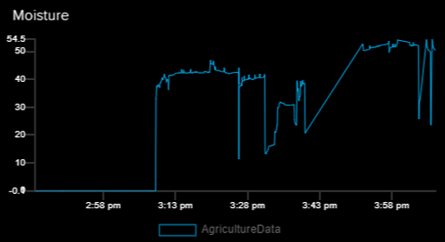
This is how NodeMCU based Smart Irrigation System using IoT works. You can expand this project by using more sensors to measures the other parameters like humidity, pressure, temperature, etc. We have previously built an ESP8266 based weather station to read all these values.
Comment below if you have any doubts regarding this project and check the demonstration video below
#include <ESP8266WiFi.h>
#include "Adafruit_MQTT.h"
#include "Adafruit_MQTT_Client.h"
const char *ssid = "Galaxy-M20"; // Enter your WiFi Name
const char *pass = "ac312124"; // Enter your WiFi Password
WiFiClient client;
#define MQTT_SERV "io.adafruit.com"
#define MQTT_PORT 1883
#define MQTT_NAME "choudharyas"
#define MQTT_PASS "988c4e045ef64c1b9bc8b5bb7ef5f2d9"
const int ledPin = D6;
const int ldrPin = D1;
const int moisturePin = A0; // moisteure sensor pin
const int motorPin = D0;
unsigned long interval = 10000;
unsigned long previousMillis = 0;
unsigned long interval1 = 1000;
unsigned long previousMillis1 = 0;
float moisturePercentage; //moisture reading
//Set up the feed you're publishing to
Adafruit_MQTT_Client mqtt(&client, MQTT_SERV, MQTT_PORT, MQTT_NAME, MQTT_PASS);
Adafruit_MQTT_Publish AgricultureData = Adafruit_MQTT_Publish(&mqtt,MQTT_NAME "/f/AgricultureData");
//Set up the feed you're subscribing to
Adafruit_MQTT_Subscribe LED = Adafruit_MQTT_Subscribe(&mqtt, MQTT_NAME "/f/LED");
Adafruit_MQTT_Subscribe Pump = Adafruit_MQTT_Subscribe(&mqtt, MQTT_NAME "/f/Pump");
void setup()
{
Serial.begin(115200);
delay(10);
mqtt.subscribe(&LED);
mqtt.subscribe(&Pump);
pinMode(motorPin, OUTPUT);
pinMode(ledPin, OUTPUT);
pinMode(ldrPin, INPUT);
digitalWrite(motorPin, LOW); // keep motor off initally
Serial.println("Connecting to ");
Serial.println(ssid);
WiFi.begin(ssid, pass);
while (WiFi.status() != WL_CONNECTED)
{
delay(500);
Serial.print("."); // print ... till not connected
}
Serial.println("");
Serial.println("WiFi connected");
}
void loop()
{
MQTT_connect();
int ldrStatus = analogRead(ldrPin);
if (ldrStatus <= 200) {
digitalWrite(ledPin, HIGH);
Serial.print("Its DARK, Turn on the LED : ");
Serial.println(ldrStatus);
}
else {
digitalWrite(ledPin, LOW);
Serial.print("Its BRIGHT, Turn off the LED : ");
Serial.println(ldrStatus);
}
moisturePercentage = ( 100.00 - ( (analogRead(moisturePin) / 1023.00) * 100.00 ) );
Serial.print("Soil Moisture is = ");
Serial.print(moisturePercentage);
Serial.println("%");
if (moisturePercentage < 35) {
digitalWrite(motorPin, HIGH); // tun on motor
}
if (moisturePercentage > 35 && moisturePercentage < 37) {
digitalWrite(motorPin, HIGH); //turn on motor pump
}
if (moisturePercentage > 38) {
digitalWrite(motorPin, LOW); // turn off mottor
}
if (! AgricultureData.publish(moisturePercentage))
{
delay(5000);
}
Adafruit_MQTT_Subscribe * subscription;
while ((subscription = mqtt.readSubscription(5000)))
{
if (subscription == &LED)
{
//Print the new value to the serial monitor
Serial.println((char*) LED.lastread);
if (!strcmp((char*) LED.lastread, "OFF"))
{
digitalWrite(ledPin, HIGH);
}
if (!strcmp((char*) LED.lastread, "ON"))
{
digitalWrite(ledPin, LOW);
}
}
if (subscription == &Pump)
{
//Print the new value to the serial monitor
Serial.println((char*) Pump.lastread);
if (!strcmp((char*) Pump.lastread, "OFF"))
{
digitalWrite(motorPin, HIGH);
}
if (!strcmp((char*) Pump.lastread, "ON"))
{
digitalWrite(motorPin, LOW);
}
}
}
}
void MQTT_connect()
{
int8_t ret;
// Stop if already connected.
if (mqtt.connected())
{
return;
}
uint8_t retries = 3;
while ((ret = mqtt.connect()) != 0) // connect will return 0 for connected
{
mqtt.disconnect();
delay(5000); // wait 5 seconds
retries--;
if (retries == 0)
{
// basically die and wait for WDT to reset me
while (1);
}
}
}


