


Ever wondered how your phone software pinpoints your location while driving using GPS? The answer to this is that a small GPS module embedded in your phone communicates with a network of satellites to determine the location of your phone. In this project, we are going to understand how a GPS module works, and we will get acquainted with one of the popular GPS receiver module called NEO 6M, this module differs in size from the one used in mobile phones but the working is same. By using the information provided by the GPS receiver module and the Thingspeak IoT platform, we will try to plot the data on the graph. In addition to this, we will also visualize the location on the satellite view map by generating a URL using the inbuild function in the Thingspeak- Matlab visualization (needs coding, which is explained in the code explanation section). By using this URL, anyone from any browser can track the location of the GPS device to which it is attached. If you are looking for a simple solution you can also check out the NodeMCU GPS Webserver project which is also very similar to what we are about to build.
Components Required
- NEO 6M GPS module
- Node MCU
- Connecting wires
How does a GPS Module work?
GPS stands for Global Positioning System, which is a worldwide radio-navigation system. To track the location of the device, the GPS tracking system uses the Global Navigation Satellite System (GNSS) Network. This network consists of a range of satellites that uses microwave signals to transmit the data which will be received by the GPS receiver module.
The GPS Satellite Constellation consists of 24 Earth-orbiting GPS satellites. These satellites are positioned in such a way that at any moment of time at least 6 of them always lie within the line of sight from anywhere on the Earth’s surface. When it comes to pinpointing the location of the GPS device, the system follows a simple mathematical principle called trilateration.

For example, consider a satellite A. When you turn on the mobile GPS, it receives the satellite A’s current time and position. Now the receiver then calculates the distance from the satellite A by calculating the time and speed of the signal (speed of the signal is equal to the speed of the light). The receiver by now knows that it has to lie on the circle formed by satellite A’s distance. Now the GPS receiver gets the data from another satellite, let’s say satellite B. By using the data provided by the satellite B, it knows that it has to lie on the interaction point between these two circles (formed by satellite A and B). Now it takes the data from the third satellite to pinpoint the exact location. This procedure of pinpointing your location by using the satellite's data like time and position Is known as Trilateration.
NEO 6M GPS Receiver Module
So, now in our project, we will be using the NEO 6M GPS receiver module, which consists of 50 channels. These channels are like rooms and each channel can accommodate one frequency per satellite. These channels are usually operated in parallel, which allows the receiver to maintain accuracy while the receiver is moving. The time to first fix (TTFF) is the time required to receive the satellite signals and navigation signals and calculate the position using that data. The TTFF for NEO 6M is 27 sec for cold start and warm start, and 1 sec for the hot start.
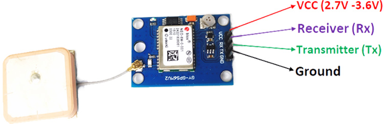
When it comes to the operating conditions, the maximum operating voltage is 3.6V and the minimum operating voltage is 2.7V. The average supply current for the NEO 6M module is 39mA. In some modules, there is an inbuilt 3.3V voltage regulator. So, we can connect the module to 5V for max performance. For communication, the module uses UART, which will be easy to communicate with any MCU (Node MCU). The connection part is discussed in the circuit diagram section. The modules pinout is shown below:
Testing the Neo 6M GPS Module
To know if the GPS module is working or not, connect the module as shown in the below circuit diagram and upload an empty code. Note that, if you are uploading an empty code, then the serial communication will take place using the default TX and RX pins of the nodeMCU. To check the data on the serial monitor, change the circuit accordingly i.e. connect the GPS module’s RX and TX to NodeMCU RX and TX as shown below
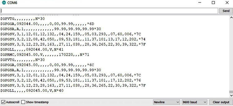
After uploading the empty code, open the serial monitor. By now, you should be seeing some values being printed on the screen. Wait, they are not the correct values. If you observe, you can find that some bits are missing in the output. At first, it takes some time for the module to give the correct values. Note: if the GPS module starts to blink, it means that the module is receiving the values. The below pic shows when the received data has some bits missing in them.
If the data doesn’t have bits missing, then the data will be like the following pic.
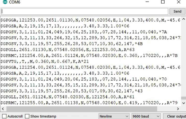
The above data that you are seeing is the data being represented by NMEA format. NMEA stands for National Marine Electronics Association. This standard data format is supported by all GPS manufacturers just like ASCII for computer manufactures.
GPGSV – Tells about the GPS satellites in view
1 = Total number of messages of this type in this cycle
2 = Message number
3 = Total number of SVs in view
4 = SV PRN number
5 = Elevation in degrees, 90 maximum
6 = Azimuth, degrees from true north, 000 to 359
7 = SNR, 00-99 dB (null when not tracking)
8-11 = Information about second SV
12-15= Information about third SV
16-19= Information about the fourth SV
GPGLL – Geographic Positioning, latitude, and longitude. For example in $GPGLL,4815.45,N,12311.12,W,215455,A
           4815.46, N    Latitude 48 deg. 15.45 min. North
           12311.12, W   Longitude 123 deg. 11.12 min. West
           215455        Fix taken at 12:54:55 UTC
             A           Data valid
Circuit Diagram for GPS Tracker
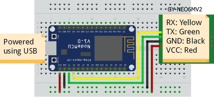
The connections between the node MCU and the NEO 6M module is simple. The VCC and GND pin of the NEO 6M module is connected to the positive and negative power rail of the breadboard, and the 3v3 and GND pin of the node MCU is connected to the positive and negative power rail of the breadboard as shown in the below fig. The RX and TX pin of the NEO 6M is connected to the D1 and D2 pins of the node MCU. The Node MCU is powered by using USB.
![]()
Setting up Thingspeak
At first, signup for thingspeak account if you are a new user. We already built many interesting projects using Thingspeak, you can also check them out.
After signing up, select the channels. After selecting channels, select New channel.

After selecting the new channel, the below page will be loaded. Enter the details and appropriate fields name and click save.
![]()
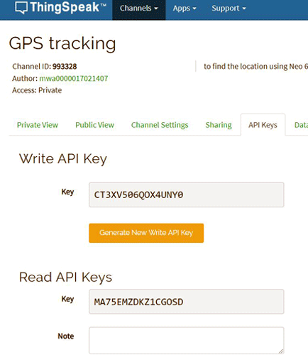
After selecting save, the below page will be loaded. Now select the option API keys
After selecting the API keys, the below page will be loaded. Now, Note down the Channel ID, Write Key and Read Key. Write key is used in the nodeMCU programming while the Read key is used in the Matlab visualization program.
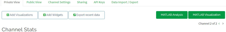
after this, select the private view option and click on the Matlab visualization option.
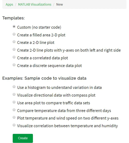
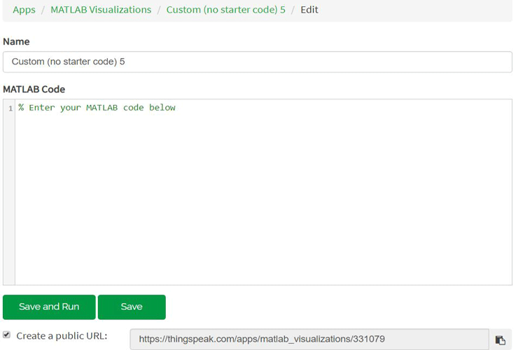
Now, the below page will be loaded. Change nothing and select Create.
Now, you will be loaded a page, where you can write the code for pointing the location on the map using the latitude and longitude. Copy-paste the code, which is provided in this article, and change the needed values( Read Key and channel ID).
Check on the create a public URL box so that by using this URL anyone can find the location of the device.
![]()
Next, we need two different types of programs. One code deals with acquiring the data from the GPS module and then to transmit the data to thingspeak. The second code deals with pointing the location on the map using the data which is sent to the thingspeak. The first is written in the Arduino IDE, while the second code is written in the thingspeak Matlab visualization.
Before getting into the code explanation, there are certain libraries which are needed to be downloaded, which helps in the conversion of raw data (NMEA format) to an understandable data. First, download the tinyGPS library using the provided link. Next, download the thingspeak library by searching it in the library manager. Download the one which is provided by MathWorks.
NodeMCU program to read GPS data and send to Thingspeak
The complete program can be found at the bottom of this page, the explanation of the same is as follows. The below snippet is used to include the libraries, which are needed for our code to work without any errors, and Setting the GPIO pins 4 and 5 as RX and TX pins of the NodeMCU. The GPS baud rate is set to 9600.
#include <TinyGPS++.h>
#include <SoftwareSerial.h>
#include "ThingSpeak.h"
#include <ESP8266WiFi.h>
static const int RXPin = 4, TXPin = 5;
static const uint32_t GPSBaud = 9600;
The below code runs only when there is incoming data from the GPS module. The code encodes the data and if the encoded data is valid, then the data is considered, and further calculation is done to transform the NMEA data to the understandable data. The below code only sends the latitude and longitude values to the thingspeak.
  while (ss.available() > 0){
    if (gps.encode(ss.read()))
    {
      if (gps.location.isValid())
      {
        latitude = gps.location.lat();
        lat_str = String(latitude , 6);
        longitude = gps.location.lng();
        lng_str = String(longitude , 6);
        Serial.print("Latitude = ");
        Serial.println(lat_str);
        Serial.print("Longitude = ");
        Serial.println(lng_str);
        ThingSpeak.setField(1, lat_str);
        ThingSpeak.setField(2, lng_str);
        ThingSpeak.writeFields(myChannelNumber, myWriteAPIKey);
      }
     delay(1000);
     Serial.println();
    }
  }
}
Matlab ThingSpeak Visualization code to display location on Map
Now, we have to write a code, which can point the location on the map by using the latitude and longitude values, which are transferred to the thingspeak. The below screenshot shows you the example URL.
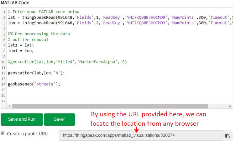
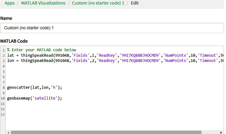
The below code takes the values of the last 10 values and locates them on the map. By using the URL, which will be available after running the code. To change the number of values, it needs to consider change the value which is written after the ‘NumPoints’.
% Enter your MATLAB code below
lat = thingSpeakRead(******,'Fields',1,'ReadKey','****************','NumPoints',10,'Timeout',50);
lon = thingSpeakRead(******,'Fields',2,'ReadKey','****************','NumPoints',10,'Timeout',50);
The below code pinpoints the location on the map using the latitude and longitude, which are provided by the nodeMCU.
geoscatter(lat,lon,'h');
geobasemap('streets');
Once your programming is complete your page should look like something as shown below
By using the provided URL, I got the below pic in the web browser.
![]()
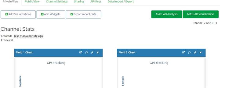
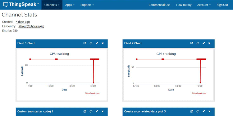
Matlab Visualization takes the data from the fields and then locates them on the map. The below pic shows the data being plotted on the fields, which will be further used for Matlab visualization.
Testing the NodeMCU GPS Tracker
As soon as you power up the nodeMCU, the readings seen in the serial monitor may not be correct. It takes some finite time to get the correct readings. You will know that the readings are correct if the GPS module starts blinking. Once the nodeMCU gets connected with a LAN, and the GPS data is valid, then this data will be sent to the thingspeak. You can check the data being updated on the fields of the Thingspeak. By using the generated URL, which we got in the Matlab visualization, we can trace the location from any browser.
![]()
The complete working can also be found in the video linked below. If you have any questions, please leave them in the comment section.
#include <TinyGPS++.h>
#include <SoftwareSerial.h>
#include "ThingSpeak.h"
#include <ESP8266WiFi.h>
static const int RXPin = 4, TXPin = 5;
static const uint32_t GPSBaud = 9600;
float latitude , longitude;
String lat_str , lng_str;
// repace your wifi username and password
const char* ssid = "Mamameya";
const char* password = "244466666";
unsigned long myChannelNumber = 991048;
const char * myWriteAPIKey = "RX9R15V8GH3941CK";
// The TinyGPS++ object
TinyGPSPlus gps;
WiFiClient client;
// The serial connection to the GPS device
SoftwareSerial ss(RXPin, TXPin);
void setup()
{
Serial.begin(115200);
ss.begin(GPSBaud);
Serial.print("Connecting to ");
Serial.println(ssid);
WiFi.begin(ssid, password);
while (WiFi.status() != WL_CONNECTED) {
delay(500);
Serial.print(".");
}
Serial.println("");
Serial.println("WiFi connected");
Serial.println("IP address: ");
Serial.println(WiFi.localIP());
Serial.print("Netmask: ");
Serial.println(WiFi.subnetMask());
Serial.print("Gateway: ");
Serial.println(WiFi.gatewayIP());
ThingSpeak.begin(client);
}
void loop()
{
while (ss.available() > 0){
if (gps.encode(ss.read()))
{
if (gps.location.isValid())
{
latitude = gps.location.lat();
lat_str = String(latitude , 6);
longitude = gps.location.lng();
lng_str = String(longitude , 6);
Serial.print("Latitude = ");
Serial.println(lat_str);
Serial.print("Longitude = ");
Serial.println(lng_str);
ThingSpeak.setField(1, lat_str);
ThingSpeak.setField(2, lng_str);
ThingSpeak.writeFields(myChannelNumber, myWriteAPIKey);
}
delay(1000);
Serial.println();
}
}
}


