In today’s world of IoT, Wi-Fi technology is taking over day by day, and the number of connected devices also increasing. Many different types of modules with different features are used to take advantage of this technology. We always want to add internet connectivity in our project and are confused about which module should be chosen. So, here is a fantastic module called the ESP8266 from Espressif Systems. Using this low-cost, small-size module, you can easily connect your device to the internet and can control any device.
Many people find the ESP8266-01 module difficult to get started. They didn’t get the proper documentation or guidance in the beginning. So, This tutorial aims to introduce you to this ESP8266-01 module and help you get started with it. Follow the given instructions here and you should be able to get your ESP8266-01 module up and running in no time.
Before getting into the technical details, let's see some basics about the ESP8266 Module.
What is ESP8266?
The ESP8266 Wi-Fi module is a complete Wi-Fi solution with microcontroller functionality and this module has powerful storage and data processing capability built on the high degree on-chip integration. Therefore, it can easily integrate with sensors and external microcontrollers for gaining the access to any Wi-Fi network.
There are many types of ESP series modules ranging from ESP8266-01 to ESP8266-12. All the modules of the ESP series have the same processor, the only difference is the breakout board which exposes the number of pins. ESP8266-01 comes last in the list in terms of the number of GPIOs. It has only 2 usable GPIOs. Also, it is a smaller one among the ESP series.
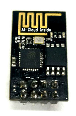
It is a very cost-effective module with a very helpful community all over the world. Also, we can program this module with the help of Arduino IDE to connect it with any available Wi-Fi network.
Specifications of ESP8266-01:
|
Voltage |
3.3V |
|
Current Consumption |
10uA-170mA |
|
Maximum current consumption during flashing |
800mA |
|
Flash Memory |
16MB (512K normal) |
|
Processor |
Tensilica L106 32 bit |
|
Processor Speed |
80-160MHz |
|
RAM |
32K+80K |
|
GPIO |
17 (but most are multiplexed) |
|
Analog to Digital Converter |
1 (10-bit) |
|
Maximum TCP connections |
5 |
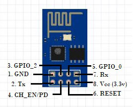
Pin Description:
|
Pin Number |
Pin Name |
Other Name |
Pin Use |
|
1 |
Ground |
- |
Connection with the ground of the circuit |
|
2 |
TX |
GPIO _1 |
Connected to Rx pin of uC to upload program, Can act as a GPIO pin when not used as TX |
|
3 |
GPIO_2 |
- |
GPIO Pin |
|
4 |
CH_EN |
- |
Chip Enable/Chip Power down – Active high, used to enable the esp8266 chip |
|
5 |
GPIO _0 |
Flash |
GPIO pin, connect this pin to GND when programming the module |
|
6 |
Reset |
- |
Resets the module |
|
7 |
RX |
GPIO_3 |
Connected to Tx pin of uC to upload the program, Can act as a GPIO pin when not used as Rx |
|
8 |
Vcc |
- |
Connect to +3.3V only |
Where to use ESP8266-01?
If you want to connect your project with the internet, then this module can be used. This module can act as an Access point i.e. it can act as a hotspot and also as a station mode which can connect this module with the Wi-fi. So, this module can easily send and receive the data over the internet and can make your device an Internet of things device. Also, this module can fetch the data available on the internet using different APIs. ESP series can also be programmed using Arduino IDE which makes ESP more user-friendly. However, It can use as a standalone module if you have to use 2 GPIOs, otherwise, you have to connect it with a microcontroller like Arduino. You can use ESP-12 or ESP-32 if you have to use more than 2 GPIOs. So, if you are looking for getting started with IoT and want to make your project Smart, then this module is for you.
How to use the ESP8266 Module
Let’s see the Software and hardware requirements for the ESP8266. Many IDEs support this module but mostly Arduino IDE is used due to its user-friendly interface and easy program structure. This module can also be programmed using AT commands and Lua script.
All the newly purchased ESP8266 modules have default firmware loaded into them. Using this inbuilt firmware, you can program it using AT commands.
If you use the Arduino IDE to program this module then you will be lost this inbuilt firmware and unable to program it using AT commands. In that case, you have to upload the new firmware to start with the AT commands.
Hardware Setup
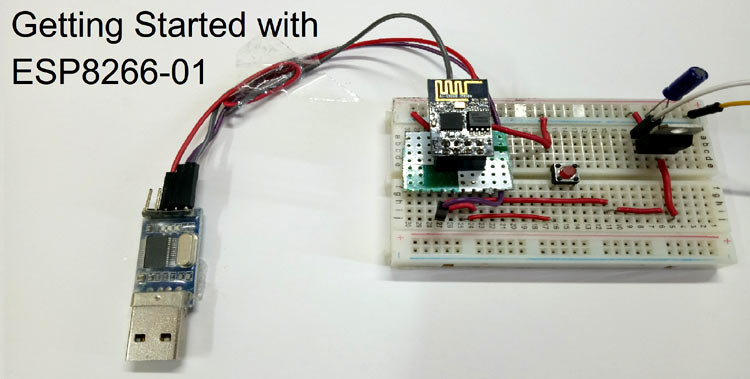
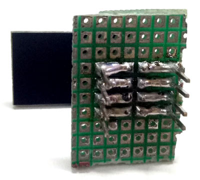
ESP8266 module works with 3.3v, voltage more than this would burn your module, so be careful with the applied voltage. Also, esp8266-01 is not breadboard friendly, you have to make a connector using male berg strips as shown below to plug it in the breadboard. Else you can use simple male-female connectors to wire other components with this module.
Programming ESP8266
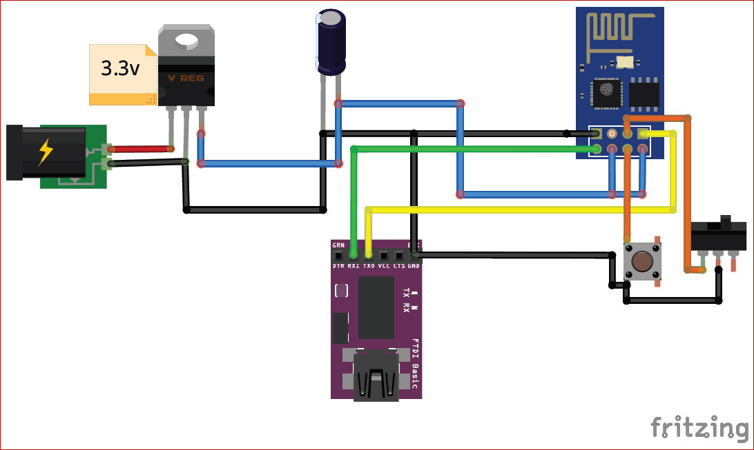
For programming the esp-01 module, you have to use USB to serial converter or Arduino Uno board without atmega328 IC. To program this module using the FTDI module, connect the circuit shown below.
If you don’t have an FTDI module, use the Arduino Uno board, just remove the Atmega328 chip and make the connections as follow:
Rx of ESP -> Rx of Arduino uno
Tx of Esp -> Tx of Arduino uno
Vcc of Esp -> 3.3v of Arduino
GND of Esp -> GND of Arduino
Replace the connections in the below circuit diagram by removing the FTDI module. If you are using an external power supply, don’t connect the Vcc of ESP with the Arduino board. Only Rx, Tx, and GND should be connected.
A simplified circuit diagram for using the ESP8266-01 module with FTDI module is given below:
In the above diagram, the Push-button is used to reset the module. To program the module using Arduino IDE and to flash new firmware in the module, make the GPIO_0 to GND using the switch button. After programming, the module removes the GND from GPIO_0.
You can make the above circuit on PCB to make the connections tight and clean.
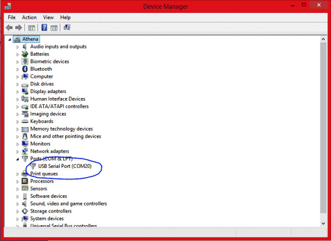
Now, connect your FTDI module to your computer using a mini-USB to USB cable. Go to Device Manager on your laptop/PC and you will find the FTDI board connected to the COM port as shown below:
Now, open the Arduino IDE and then the Serial monitor. Make the baud rate 115200 and select Both NL and CR.
Reset the module using a Push-button, you should see some garbage values and then a ready message on the serial monitor. Now type AT and hit enter, it will reply with OK.
Now, your module is ready to work in AT commands. To learn about AT commands read this documentation.


