


In this project, we are going to integrate Adafruit IO with Zapier to send Email Notifications whenever the data published in the Adafruit IO Feed. We are going to use NodeMCU and BMP180 sensor. Earlier we have used IFTTT in many IoT projects to send Email notifications.
Zapier is an online automation tool that integrates your favorite apps like Gmail, Facebook, Google Sheets, etc. with IoT based services like Adafruit. Using Zapier, you can integrate two or more applications to automate repetitive tasks without coding. It's very easy and anyone can build their own app workflow within few clicks.
For example, if you receive many attachments in emails and want to save them in Dropbox, you can easily automate this task using Zapier. It can save your time and effort in manually putting them in dropbox.
Components Required
Hardware
- NodeMCU ESP8266
- BMP180 Pressure Sensor
- Jumper Wires
Software & Online Services
- Adafruit IO
- Zapier
We previously used Adafruit with many boards like Raspberry Pi, ESP8266, ESP32, etc. to build IoT based applications.
Circuit Diagram
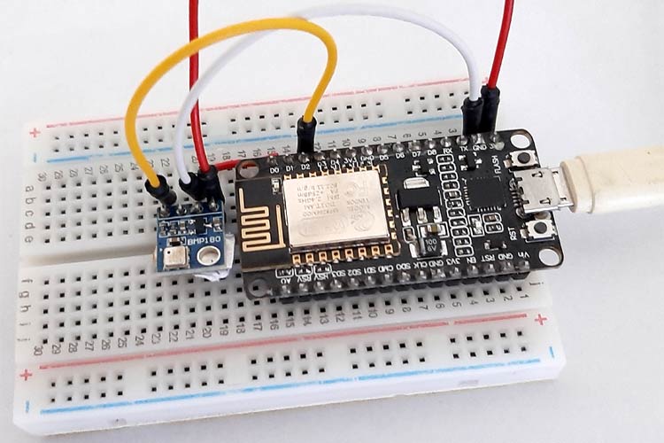
Circuit Diagram for this Zapier integration with NodeMCU is simple as we are only interfacing BMP180 with NodeMCU.
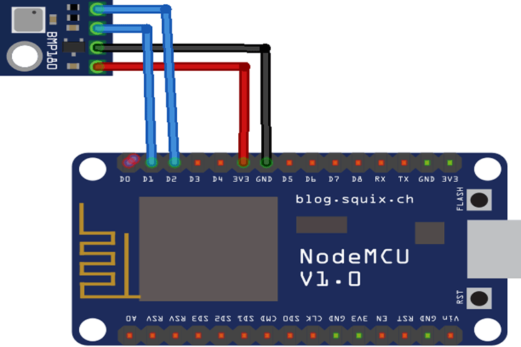
The BMP180 sensor uses the I2C communication protocol. So, you need to connect the SCL and SDA pins of BMP180 to SCL and SDA pins (D1 and D2) of NodeMCU. Also, connect the VIN and GND pin of BMP180 to 3.3V and GND of NodeMCU. Do not connect the Sensor directly to 5V, and it can damage the Sensor permanently.
Adafruit IO Setup
Adafruit IO is an open data platform that allows you to aggregate, visualize, and analyze live data on the cloud. Using Adafruit IO, you can upload, display, and monitor your data over the internet, and make your project IoT enabled. You can control motors, read sensor data, and make cool IoT applications over the internet using Adafruit IO. We previously used the Adafruit Platform to build many IoT projects.
To publish data to Adafruit IO, sign in to your Adafruit IO account if you have one or create an account on Adafruit IO.
1. To create an account, go to the Adafruit IO website and click on ‘Get started for Free’ on the top right of the screen.

2. After this, a window will pop up where you need to fill your details
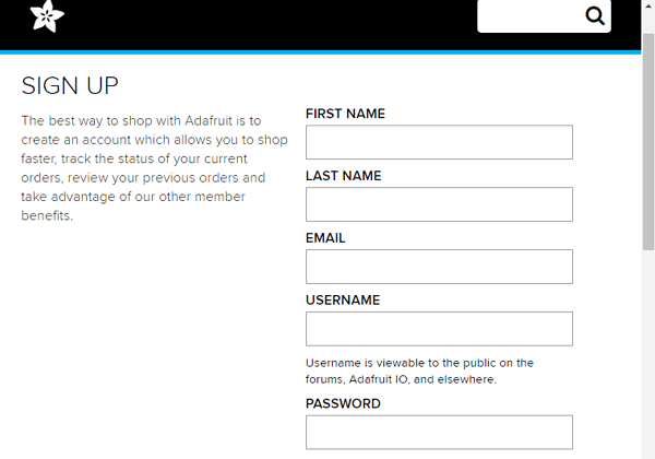
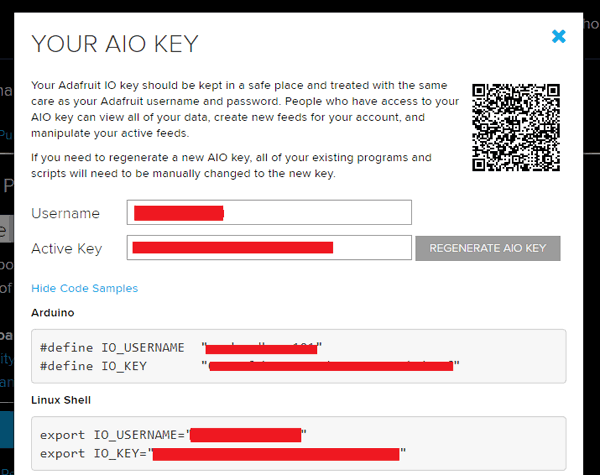
In sign up window, fill your details like your name, mail id, username, etc. Then click on save settings and your account is created. To get your AIO key, click on ‘View AIO Key’.
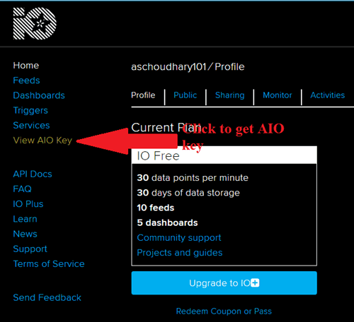
3. A window will pop up with your Adafruit IO AIO Key. Copy this key, you'll need it later in your python code.
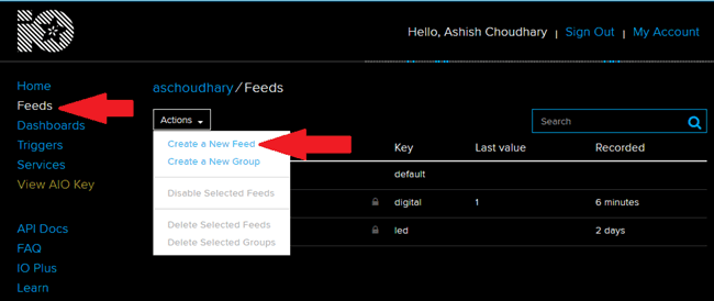
4. Now after this, you need to create a feed. To create a feed, click on ‘Feed’. Then click on ‘Actions’, you will see some options from them click on ‘Create a New Feed’.
5. After this, a new window will open where you need to input:
Name – In name option, write a short descriptive name of your feed. You can use letters, numbers, and spaces.
Description - A long-form description of your data. This field is not required, but you can write a description about your data.
6. Click on ‘Create’, you will then be redirected to your new feed.
You can also use the Adafruit IO Dashboard to add some widgets like Gauge, Line Chart, or Stream widget to visualize your data on Adafruit IO.
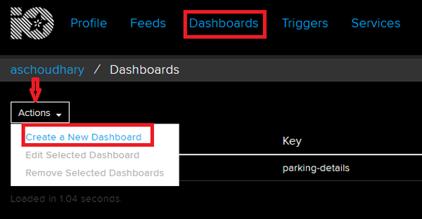
To create a dashboard, click on the Dashboard option and then click on the ‘Action,’ and after this, click on ‘Create a New Dashboard.’
In the next window, enter the name for your dashboard and click on ‘Create.’
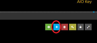
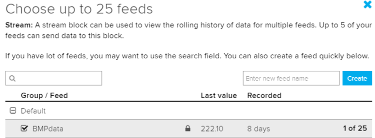
As the dashboard is created, now we will add our feeds in the dashboard. To add a feed, click on the ‘+’ in the top right corner and select a widget from the available options.
The dashboard gets the data from Feeds. So select your BMP data feed.
Now your Adafruit IO account setup is complete.
Programming the NodeMCU for Zapier Integration
Here we are programming the NodeMCU to get the data from the BMP180 sensor and publish it to the Adafruit IO Dashboard. The complete code is given at the end of the document. Here we are explaining some important parts of the code for better understanding.
As usual, start the code by including all the required libraries.
#include <ESP8266WiFi.h>
#include <Wire.h>
#include <Adafruit_BMP085.h>
#include "Adafruit_MQTT.h"
#include "Adafruit_MQTT_Client.h"
After this, enter the Adafruit IO username and AIO key that you copied from the Adafruit IO server. The server address and port number will be the same for all.
#define MQTT_SERV "io.adafruit.com"
#define MQTT_PORT 1883
#define MQTT_NAME "Your Username"
#define MQTT_PASS "Adafruit IO Key"
Set up the feed you're publishing to. Here ‘BMPdata’ is the feed name.
Adafruit_MQTT_Client mqtt(&client, MQTT_SERV, MQTT_PORT, MQTT_NAME, MQTT_PASS);
Adafruit_MQTT_Publish BMPdata = Adafruit_MQTT_Publish(&mqtt,MQTT_NAME "/f/BMPdata");
Inside the void setup() function, initialize the baud rate, BMP180 using .begin() function, then connect the module with the Wi-Fi.
Serial.begin(115200);
  if (!bmp.begin()) {
  Serial.println("Could not find a valid BMP085 sensor, check wiring!");}
Serial.print("Connecting to ");
Serial.println(ssid);
WiFi.begin(ssid, password);
while (WiFi.status() != WL_CONNECTED) {
delay(500);
Serial.print(".");
}
Serial.println("");
Serial.println("WiFi is connected");
Now inside the void loop, read the temperature, pressure, and Altitude values from BMP180 Sensor and store these values in different variables. After that, publish these readings to the Adafruit IO Dashboard.
void loop() {
 MQTT_connect();
 float p = bmp.readPressure()/100;
 Serial.print("Pressure = ");
 Serial.println(" mb");
 float a = bmp.readAltitude();
 Serial.print(a);
 float temperature = bmp.readTemperature();
 Serial.print(temperature);
 delay(4000);
  if (! BMPdata.publish(temperature))
       {
  Delay(3000);
                   }
  }
Integrate Zapier with Adafruit IO
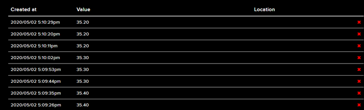
Once your code and Hardware are ready, connect the NodeMCU to your laptop and upload the code. Now open the serial monitor to check if NodeMCU is reading the data or not. Once confirmed that everything is working, navigate to your Adafruit IO account to check if the sensor data is published or not. If published, then your Adafruit IO Feed will look like this:
Now we will integrate the Adafruit IO with Zapier to send us the email notifications. To do this, go to Zapier and create a new account.
Now follow the below steps to create your own Zap.
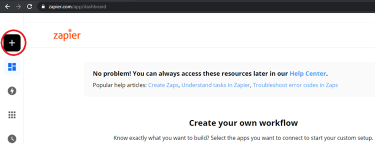
In your Zapier account, click on ‘Make a Zap’ in the left sidebar menu.
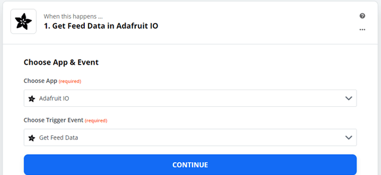
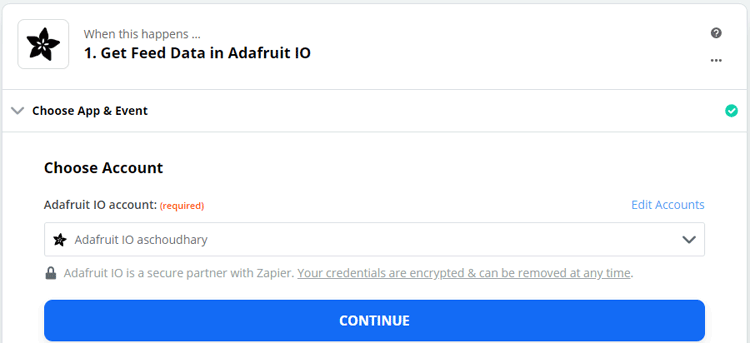
In the first step, you have to select a trigger app. In our case, we are getting the data from Adafruit IO, so it will be our trigger app. Select the Adafruit IO from available options.
Now in the second step, select your trigger event. Whenever this event happens, it triggers the Zap.
After selecting the App and Trigger event, select the App account. You have to sign in to your Adafruit account from Zapier.
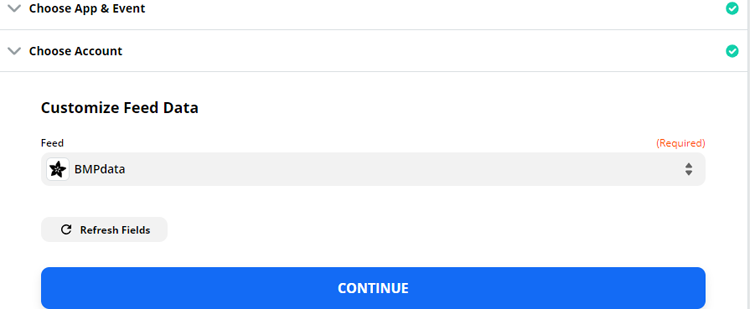
Now in the next step, select the Feed (Where you are publishing the Data).
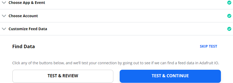
In the final step, test your trigger by clicking on ‘Test & Continue’. When your trigger is set up successfully, a green checkmark icon will appear in the top left of the step.
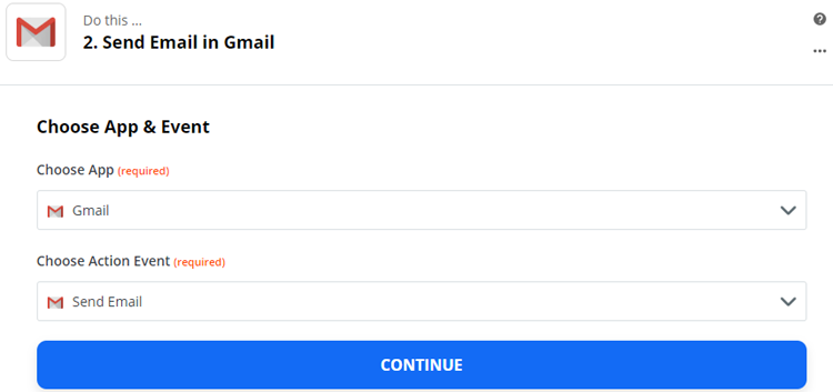
After setting up the trigger, now you have to set up the action field. Here we want to receive email updates whenever NodeMCU publishes data in the Feed. So select ‘Gmail’ as your action app.
And in the next step, select ‘Send Email’ as the action event.
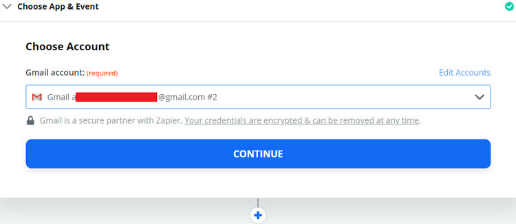
Now in the next step, select the Gmail account and click on ‘Continue.’
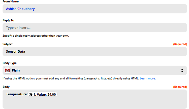
Now in the next step, enter the recipient name, subject of the mail, and the body of the mail. You can also enter the sender's name.
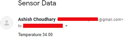
In the final step, test your action. When you click on ‘Test & Continue’, it will send you a test mail like this:
This is how Zapier can be used to send email notifications. Zapier can also send notifications using Telegram, Messenger, or Twitter.
#include <ESP8266WiFi.h>
#include <Wire.h>
#include <Adafruit_BMP085.h>
#include "Adafruit_MQTT.h"
#include "Adafruit_MQTT_Client.h"
Adafruit_BMP085 bmp;
#define MQTT_SERV "io.adafruit.com"
#define MQTT_PORT 1883
#define MQTT_NAME "Adadfruit IO Username"
#define MQTT_PASS "AIO Key"
WiFiClient client;
const char* ssid = "Wi-Fi Name"; // Your ssid
const char* password = "Password"; // Your Password
char status;
Adafruit_MQTT_Client mqtt(&client, MQTT_SERV, MQTT_PORT, MQTT_NAME, MQTT_PASS);
Adafruit_MQTT_Publish BMPdata = Adafruit_MQTT_Publish(&mqtt,MQTT_NAME "/f/BMPdata");
void setup() {
Serial.begin(115200);
delay(100);
if (!bmp.begin()) {
Serial.println("Could not find a valid BMP085 sensor, check wiring!");
while (1) {}
}
Serial.print("Connecting to ");
Serial.println(ssid);
WiFi.begin(ssid, password);
while (WiFi.status() != WL_CONNECTED) {
delay(500);
Serial.print(".");
}
Serial.println("");
Serial.println("WiFi is connected");
}
void loop() {
MQTT_connect();
float p = bmp.readPressure()/100;
Serial.print("Pressure = ");
Serial.print(p);
Serial.println(" mb");
// Calculate altitude assuming 'standard' barometric
// pressure of 1013.25 millibar = 101325 Pascal
float alt = bmp.readAltitude();
Serial.print("Altitude = ");
Serial.print(alt);
float temperature = bmp.readTemperature();
Serial.print("Temperature= ");
Serial.print(temperature);
//delay(4000);
if (! BMPdata.publish(temperature))
{
//delay(5000);
}
delay(9000);
}
void MQTT_connect()
{
int8_t ret;
// Stop if already connected.
if (mqtt.connected())
{
return;
}
uint8_t retries = 3;
while ((ret = mqtt.connect()) != 0) // connect will return 0 for connected
{
mqtt.disconnect();
delay(5000); // wait 5 seconds
retries--;
if (retries == 0)
{
// basically die and wait for WDT to reset me
while (1);
}
}
}


