


ESP RainMaker is an end-to-end solution for ESP chips by Espressif. It enables users to build wireless control and remote monitoring devices based on all types of AIoT solutions using ESP32, with a single-click deployment. This platform offers easy accessibility, free integration of Alexa and Google Assistant, free cloud deployment, and WIFI provisioning through QR code. Developers can write firmware and immediately interact with it via phone apps or voice assistants, without any coding required in the cloud or phone applications. This allows makers to concentrate solely on firmware development, without concerns regarding the app or cloud integration and other infrastructure.
The necessary components of this solution are:
- Claiming Service (to get the Cloud connectivity credentials)
- RainMaker Agent (i.e., Rainmaker repo, to develop the firmware)
- RainMaker Cloud (backend, offering remote connectivity)
- RainMaker Phone App/CLI (Client utilities for remote access)
In this project, we will be going to control a led connected to ESP32 using the ESP Rainmaker App from our mobile over the cloud. ESP32 board and smartphone both need to connect to steady internet for smooth working without lagging.
Workflow of ESP RainMaker
Let see how the application to be connected and configured with ESP32 and make it to be able to communicate with the IoT cloud platform.
- First, programmed the ESP32 board with ESP Rainmaker firmware, after successful uploading, a QR code is generated and displayed on the serial monitor (don’t forget to set the correct Baud Rate).
- Once the app scans the QR code, it will initiate the BLE communication with the ESP32 board.
- The ESP32 receives Network credentials through Bluetooth communication, allowing it to connect to a WIFI signal and establish a connection with the ESP Rainmaker cloud.
- All sensor data will be communicated to ESP Rainmaker cloud which we can access either through the cloud service or the mobile app.
Components Required for ESP RainMaker
- ESP32 board
- Led bulb (5v)
- Breadboard
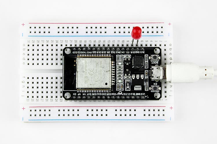
Circuit Diagram for Interfacing ESP32
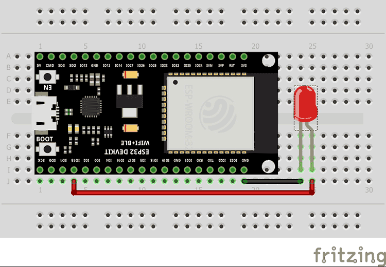
Now let’s start with interfacing a led with ESP32. We connected the positive terminal of the lead to GPIO pin 15 and another to the GND of ESP32. And for the switch, we will use the onboard boot switch.
Programming ESP32 with Arduino IDE
Let’s look at how can we use Arduino IDE for installing ESP rainmaker firmware to the ESP32 board. For that, we need to install ESP32 board packages version 2.0 which has support for ESP Rainmaker. If you have an older package installed, upgrade it to v2.0.
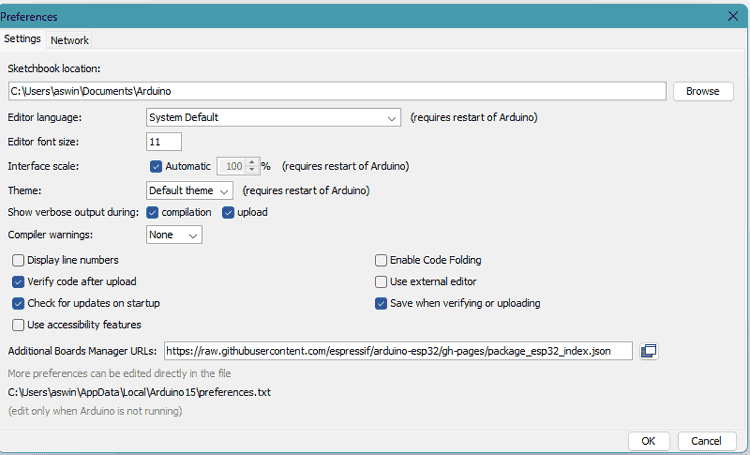
- Open your Arduino IDE, and head over to File > Preferences. Now paste the following link in the Additional Boards Manager URLs and press Ok.
https://raw.githubusercontent.com/ESPressif/arduino-ESP32/gh-pages/package_ESP32_index.json
- Open the Arduino IDE and navigate to the Board Manager. Install the latest version of ESP32.
- Select the ESP32 Dev Module as the board and choose the appropriate flash size and partition scheme as RainMaker. Also, enable Erase all Flash Before Sketch Upload.
- Copy and compile the example code provided below.
- Upload the compiled code to the ESP32 development board by choosing the correct port.
- After successfully uploading the code, open the serial monitor and set the baud rate to 115200.
- Now press the enable button on ESP32. Now a QR code is generated and displayed on the serial monitor.
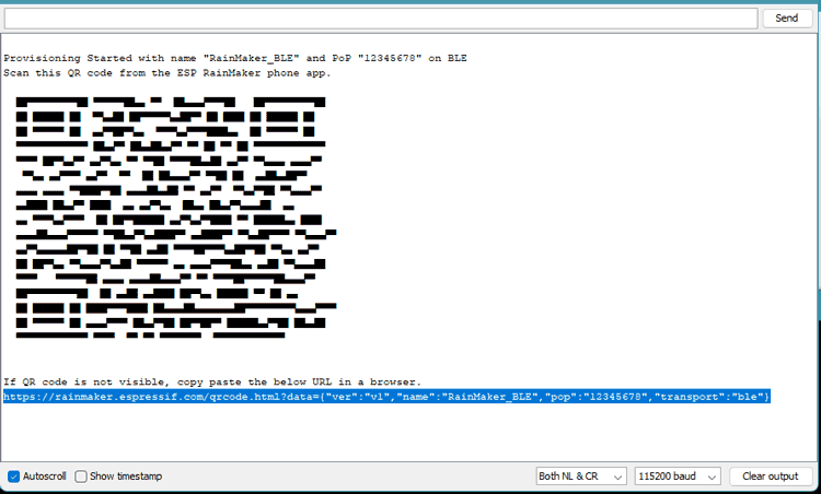
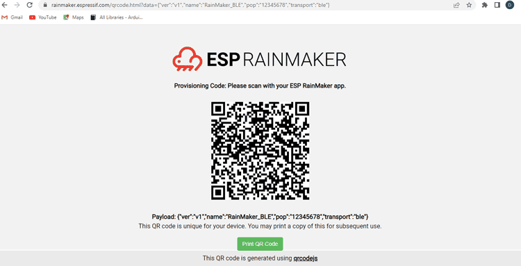
- If the QR code is not proper as shown above, copy the URL at the bottom of the serial monitor and paste it to any browser. The browser will now show the correct and neat QR code. This is the QR code that we will scan with our ESP RainMaker app to configure it.
ESP Rainmaker Application Configure
- Download the ESP RainMaker app & install it on your Smartphone. Open the app and log in to it.
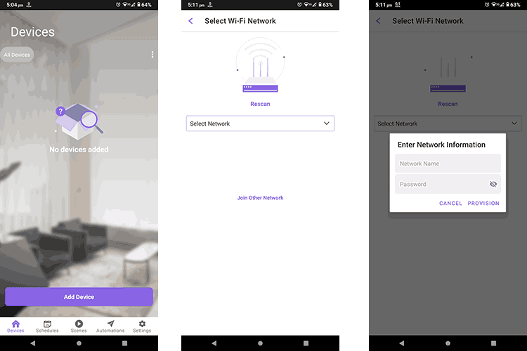
- If you haven’t added any device previously the app will show the home screen with add device button.
- Now, Turn-On the Bluetooth of your smartphone. Click on “Add Device” and Scan the QR code displayed in the browser.
- Now app tries to establish BLE communication with the ESP32 board. Once it is connected, the app will show a screen to select the WIFI connection.
- If your phone doesn’t show any Wi-Fi networks in the app, you can enter the WIFI credentials manually by clicking on the Join Other Network Option.
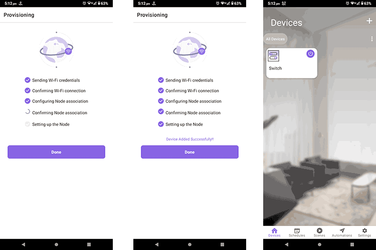
- Now the Provisioning process starts. It consists of several steps that are verified before the device is successfully added. Click done after all steps are ticked.
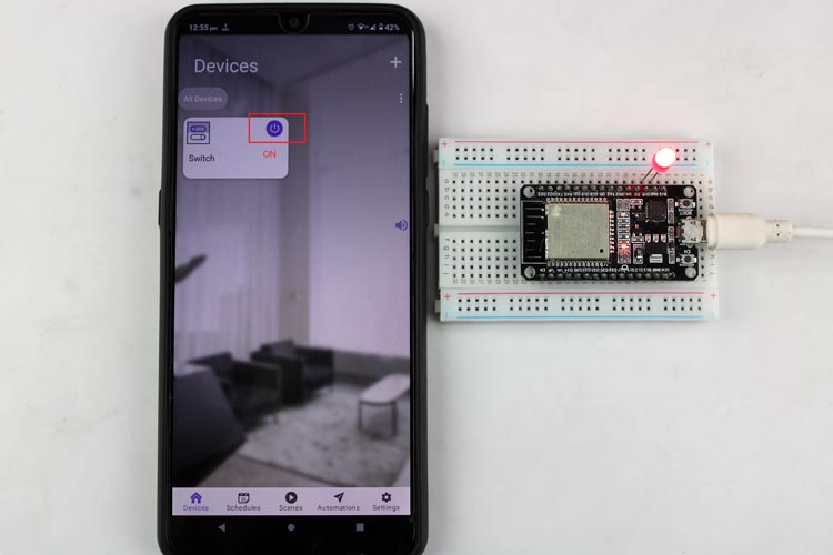
- After the setup process is completed, the ESP will connect to the WIFI network and appear as a new device named "Switch" on the app's home screen. The LED can then be controlled using the switch button within the app.
Arduino Code Explanation
Firstly, we must include all necessary Libraries for the successful execution of the code. Libraries include RMaker.h, Wifi.h, WifiProv.h only.
#include "RMaker.h"
#include "WiFi.h"
#include "WiFiProv.h"
Since the ESP32 communicates with Bluetooth so we have defined Bluetooth credentials using the pointers service_name and pop, which will be used while the provisioning.
const char *service_name = "RainMaker_BLE";
const char *pop = "12345678";
Then we have defined the GPIO pins used for the LED and switch. We have also created a Boolean variable called switch_state to store the switch status.
//GPIO for virtual device
static int gpio_0 = 0;
static int gpio_switch = 15;
/* Variable for reading pin status*/
bool switch_state = true;
//The framework provides some standard device types like switch, lightbulb, fan, temperaturesensor.
static Switch my_switch;
The sysProvEvent() function obtains Wi-Fi credentials and connects ESP32 to the router for system provisioning events.
void sysProvEvent(arduino_event_t *sys_event) {
    switch (sys_event->event_id) {
        case ARDUINO_EVENT_PROV_START:
#if CONFIG_IDF_TARGET_ESP32S2
        Serial.printf("\nProvisioning Started with name \"%s\" and PoP \"%s\" on SoftAP\n", service_name, pop);
        printQR(service_name, pop, "softap");
#else
        Serial.printf("\nProvisioning Started with name \"%s\" and PoP \"%s\" on BLE\n", service_name, pop);
        printQR(service_name, pop, "ble");
#endif
        break;
        default:;
    }
}
The write_callback() function checks the device that sent data and adjusts its parameters. It is specifically designed for the device LED and determines whether the LED should turn on or off based on the state of the LED pin. If the device is 'LED' and the parameter is 'Power', the function turns the LED on if the power is HIGH and off if the power is LOW.
void write_callback(Device *device, Param *param, const param_val_t val, void *priv_data, write_ctx_t *ctx) {
    const char *device_name = device->getDeviceName();
    const char *param_name = param->getParamName();
    if(strcmp(param_name, "Power") == 0) {
        Serial.printf("Received value = %s for %s - %s\n", val.val.b? "true" : "false", device_name, param_name);
        switch_state = val.val.b;
        (switch_state == false) ? digitalWrite(gpio_switch, LOW) : digitalWrite(gpio_switch, HIGH);
        param->updateAndReport(val);
    }
}
In the setup() function, we open serial communication at 115200 baud and configure the reset and LED pins using the pinMode() function with the GPIO pin as the first parameter and the mode as the second parameter. The reset pin is set as an input pin, while the LED pin is set as an output pin. The LED pin is initially set to a LOW state.
void setup() {
    Serial.begin(115200);
    pinMode(gpio_0, INPUT);
    pinMode(gpio_switch, OUTPUT);
    digitalWrite(gpio_switch, DEFAULT_POWER_MODE);
Then we will declare a node with the name “ESP RainMaker Node”. Later we declared the switch device. We also declared the call-back function for the switch device and enabled the time zone service. Later we started the RainMaker band using Rmaker.start function and called the sysProEvent function after that for provisioning.
Node my_node;
    my_node = RMaker.initNode("ESP RainMaker Node");
    //Initialize switch device
    my_switch = Switch("Switch", &gpio_switch);
    //Standard switch device
    my_switch.addCb(write_callback);
    //Add switch device to the node
    my_node.addDevice(my_switch);
    //This is optional
    RMaker.enableOTA(OTA_USING_PARAMS);
    //If you want to enable scheduling, set time zone for your region using setTimeZone().
    //The list of available values are provided here https://rainmaker.ESPressif.com/docs/time-service.html
    // RMaker.setTimeZone("Asia/Shanghai");
    // Alternatively, enable the Timezone service and let the phone apps set the appropriate timezone
    RMaker.enableTZService();
    RMaker.enableSchedule();
    RMaker.start();
    WiFi.onEvent(sysProvEvent);
#if CONFIG_IDF_TARGET_ESP32S2
    WiFiProv.beginProvision(WIFI_PROV_SCHEME_SOFTAP, WIFI_PROV_SCHEME_HANDLER_NONE, WIFI_PROV_SECURITY_1, pop, service_name);
#else
    WiFiProv.beginProvision(WIFI_PROV_SCHEME_BLE, WIFI_PROV_SCHEME_HANDLER_FREE_BTDM, WIFI_PROV_SECURITY_1, pop, service_name);
#endif
}
The loop monitors GPIO 0 and updates the switch_state parameter accordingly. Additionally, it prints the status change to the serial monitor for debugging purposes.
void loop() {
    if(digitalRead(gpio_0) == LOW) { //Push button pressed
        // Key debounce handling
        delay(100);
        int startTime = millis();
        while(digitalRead(gpio_0) == LOW) delay(50);
        int endTime = millis();
        if ((endTime - startTime) > 100) {
          // Toggle device state
          switch_state = !switch_state;
          Serial.printf("Toggle State to %s.\n", switch_state ? "true" : "false");
          my_switch.updateAndReportParam(ESP_RMAKER_DEF_POWER_NAME, switch_state);
          (switch_state == false) ? digitalWrite(gpio_switch, LOW) : digitalWrite(gpio_switch, HIGH);
      }
    }
    delay(100);
}
Working of the project ESP RainMaker
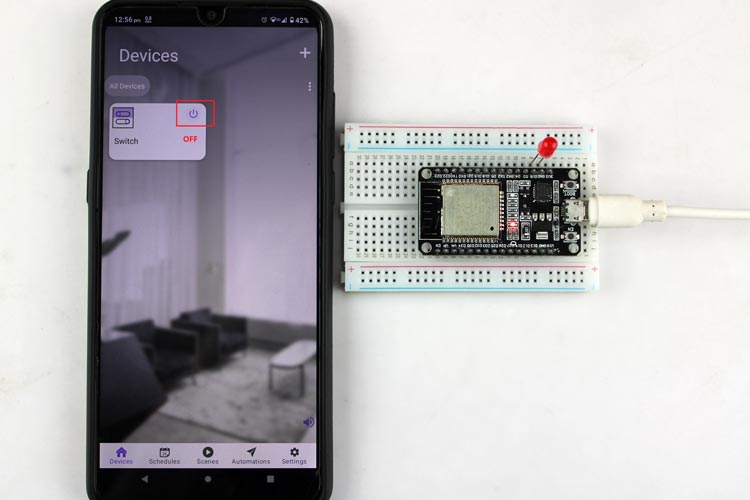
Tap on Switch Button on Rainmaker App
Hope you enjoyed the article and learned something useful from it. If you have any questions, you can leave them in the comment section below.
#include "RMaker.h"
#include "WiFi.h"
#include "WiFiProv.h"
#define DEFAULT_POWER_MODE true
const char *service_name = "RainMaker_BLE";
const char *pop = "12345678";
//GPIO for virtual device
static int gpio_0 = 0;
static int gpio_switch = 15;
/* Variable for reading pin status*/
bool switch_state = true;
//The framework provides some standard device types like switch, lightbulb, fan, temperaturesensor.
static Switch my_switch;
void sysProvEvent(arduino_event_t *sys_event)
{
switch (sys_event->event_id) {
case ARDUINO_EVENT_PROV_START:
#if CONFIG_IDF_TARGET_ESP32S2
Serial.printf("\nProvisioning Started with name \"%s\" and PoP \"%s\" on SoftAP\n", service_name, pop);
printQR(service_name, pop, "softap");
#else
Serial.printf("\nProvisioning Started with name \"%s\" and PoP \"%s\" on BLE\n", service_name, pop);
printQR(service_name, pop, "ble");
#endif
break;
default:;
}
}
void write_callback(Device *device, Param *param, const param_val_t val, void *priv_data, write_ctx_t *ctx)
{
const char *device_name = device->getDeviceName();
const char *param_name = param->getParamName();
if(strcmp(param_name, "Power") == 0) {
Serial.printf("Received value = %s for %s - %s\n", val.val.b? "true" : "false", device_name, param_name);
switch_state = val.val.b;
(switch_state == false) ? digitalWrite(gpio_switch, LOW) : digitalWrite(gpio_switch, HIGH);
param->updateAndReport(val);
}
}
void setup()
{
Serial.begin(115200);
pinMode(gpio_0, INPUT);
pinMode(gpio_switch, OUTPUT);
digitalWrite(gpio_switch, DEFAULT_POWER_MODE);
Node my_node;
my_node = RMaker.initNode("ESP RainMaker Node");
//Initialize switch device
my_switch = Switch("Switch", &gpio_switch);
//Standard switch device
my_switch.addCb(write_callback);
//Add switch device to the node
my_node.addDevice(my_switch);
//This is optional
RMaker.enableOTA(OTA_USING_PARAMS);
//If you want to enable scheduling, set time zone for your region using setTimeZone().
//The list of available values are provided here https://rainmaker.ESPressif.com/docs/time-service.html
// RMaker.setTimeZone("Asia/Shanghai");
// Alternatively, enable the Timezone service and let the phone apps set the appropriate timezone
RMaker.enableTZService();
RMaker.enableSchedule();
RMaker.start();
WiFi.onEvent(sysProvEvent);
#if CONFIG_IDF_TARGET_ESP32S2
WiFiProv.beginProvision(WIFI_PROV_SCHEME_SOFTAP, WIFI_PROV_SCHEME_HANDLER_NONE, WIFI_PROV_SECURITY_1, pop, service_name);
#else
WiFiProv.beginProvision(WIFI_PROV_SCHEME_BLE, WIFI_PROV_SCHEME_HANDLER_FREE_BTDM, WIFI_PROV_SECURITY_1, pop, service_name);
#endif
}
void loop() {
if(digitalRead(gpio_0) == LOW) { //Push button pressed
// Key debounce handling
delay(100);
int startTime = millis();
while(digitalRead(gpio_0) == LOW) delay(50);
int endTime = millis();
if ((endTime - startTime) > 100) {
// Toggle device state
switch_state = !switch_state;
Serial.printf("Toggle State to %s.\n", switch_state ? "true" : "false");
my_switch.updateAndReportParam(ESP_RMAKER_DEF_POWER_NAME, switch_state);
(switch_state == false) ? digitalWrite(gpio_switch, LOW) : digitalWrite(gpio_switch, HIGH);
}
}
delay(100);
}


