


ESP32 is the successor of the popular ESP8266 Wi-Fi module, with many advanced features such as a dual-core 32-bit CPU with built-in Wi-Fi and dual-mode Bluetooth with a sufficient amount of 30 I/O pins. It is capable of functioning reliably in industrial environments, with operating temperature ranging from –40°C to +125°C. It has a wide variety of peripherals available like capacitive touch, ADCs, DACs, UART, SPI, I2C, etc. In addition to that, it also has a built-in hall effect sensor and a built-in temperature sensor.
ESP32 can be programmed directly from the Arduino IDE which makes it easy to work for the large community of Arduino developers. Here in this ESP32 getting started tutorial, we will configure ESP32 in Arduino IDE and program it to Blink an LED. So, let’s get started with the ESP32 development board.
Materials Required
- ESP32 Module
- USB cable
- Arduino IDE
ESP32 Specifications and Pinout
Before we actually get started with ESP32 programming, let's first check the specifications of ESP32. As mentioned earlier, it has a dual-core processor which means it has two processors. The ESP32 will run on breakout boards and modules from 160MHz up to 240MHz which is a very good speed for anything that requires a microcontroller with connectivity options.
As you can see, the processor used in ESP32 is ESP-WROOM-32 which is a 32bit microprocessor. The below picture shows the schematics diagram of ESP32:
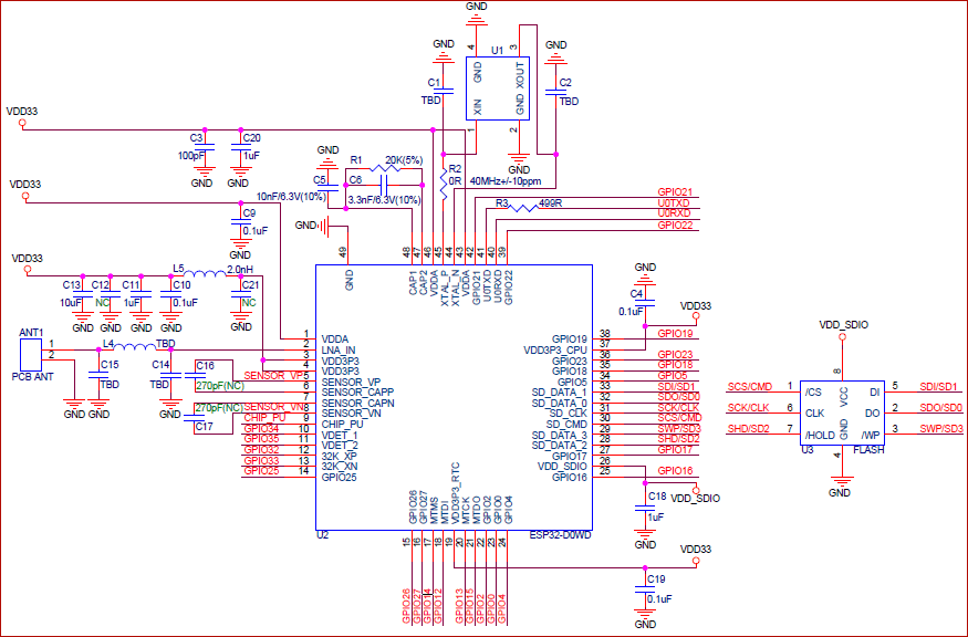
Any basic ESP32 circuit design can be divided into eight major sections:
- Power Supply
- Power-on sequence and system reset
- Flash
- Crystal Oscillator
- RF
- ADC
- External Capacitors
- UART
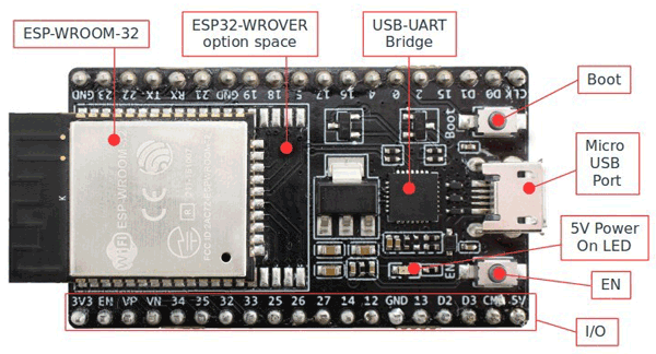
It has a couple of buttons and LEDs which are explained below:
- Micro USB Port: This port is used to connect ESP32 to our computer for programming by using a USB cable.
- Boot Button: Boot button is used to upload the program from Arduino IDE into ESP32 after clicking on the upload icon on the Arduino IDE. Please make sure that don’t press the EN button with the Boot button otherwise ESP enters into firmware uploading mode.
- EN Button: The EN button is used to reset the ESP module.
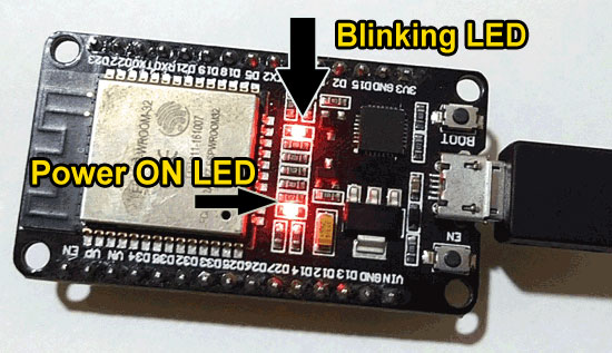
- Power-On LED: It is used to indicate the power supply, glows red when powered.
- I/O Pins: The ESP32 has more pins than ESP8266, With the ESP32 you can decide which pins are UART, SPI, or I2C. You just need to set on the code, this becomes possible due to the ESP32 chip multiplexing feature. If you don’t set them on the code the pins will be used as default.
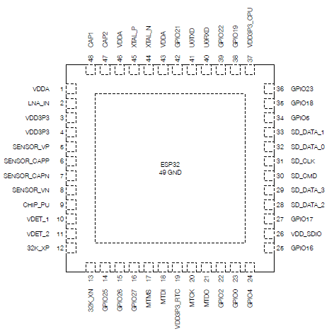
For more details about pin description, you can refer ESP32 datasheet.
USB-UART Bridge: The USB to UART Bridge Controller is a fully integrated USB to UART controller that provides USB connectivity to devices with a UART interface.
Preparing ESP32 in Arduino IDE
Step 1: First you need to download and install Arduino IDE software which you can download from https://www.arduino.cc/en/Main/Software for free. If you have already installed Arduino IDE on your PC, then make sure that it is the latest version of IDE as the older version doesn’t include the ESP32 board.
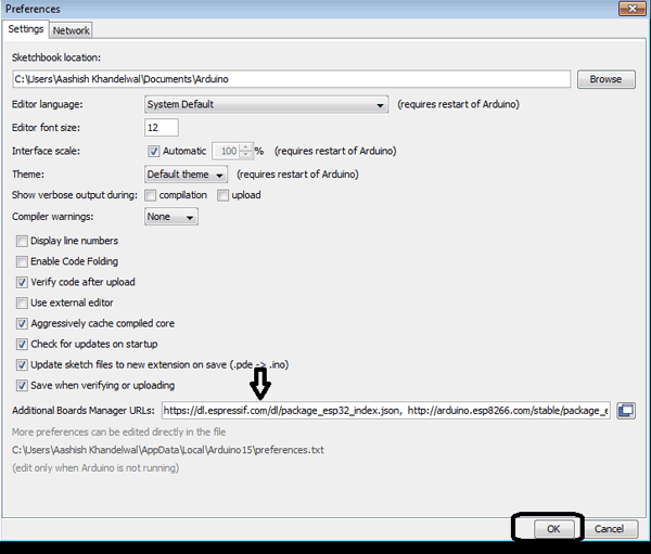
Step 2: After installing, open IDE and go to Files -> Preferences and open preference window and see the “Additional Boards Manager URL’s” as:
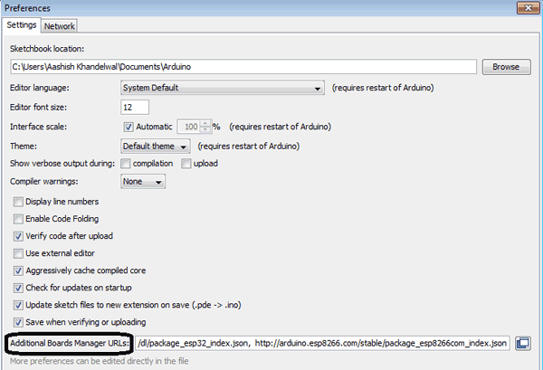
Step 3: This box may be empty or contain some other URL if you have used it previously for ESP8266. You just have to paste the below URL into this box if the box contains already another URL, then paste it by separating another URL using comma(,).
https://dl.espressif.com/dl/package_esp32_index.json
Step 4: After pasting the given URL my window looks like this as I already used ESP82666, Now press OK and the window will disappear.
Step 5: Now go to Tools-> Board-> Board Manager and search for ESP32 and press install, it will take some time to install, make sure that you have an internet connection; after installing, your window looks like this:
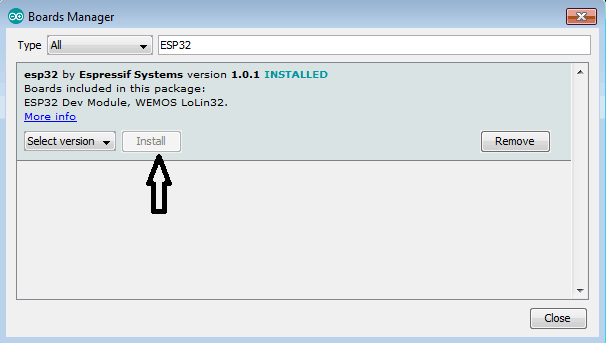
After this, close the window of board manager and your Arduino IDE is ready to program ESP32.
Programming ESP32 With Arduino IDE
Now you are ready to program your ESP32 using Arduino IDE according to your requirements. Following are the steps required to program the ESP32 with Arduino IDE. Here we will upload an LED binky program in ESP32 using Arduino IDE.
Step 1: First of all, connect your ESP32 to your computer using a micro-USB cable, make sure that Red LED goes high after connecting it with the PC.
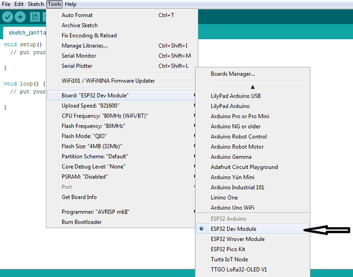
Step 2: Now you have to select your board; so go to Tools-> Boards and select “ESP32 Dev Module”.
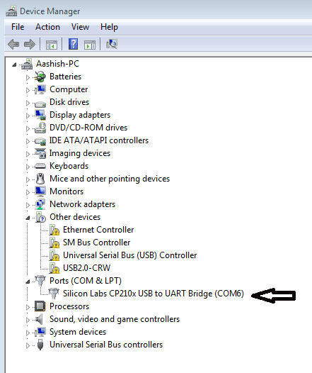
Step 3: Now open device manager and check to which com port ESP32 is connected. Here, my ESP is connected to port6.
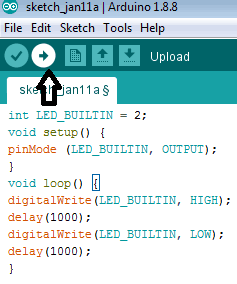
Step 4: Open Arduino IDE again and paste the given LED blink program:
int LED_BUILTIN = 2;
void setup() {
pinMode (LED_BUILTIN, OUTPUT);
}
void loop() {
digitalWrite(LED_BUILTIN, HIGH);
delay(1000);
digitalWrite(LED_BUILTIN, LOW);
delay(1000);
}
In ESP32, the internal LED is connected to pin no. 2; so I define that pin of ESP as high or low. This code makes LED blink every 1 second, you can change the interval by changing the delay.
Step 5: To upload the code in ESP32, click on the upload button.
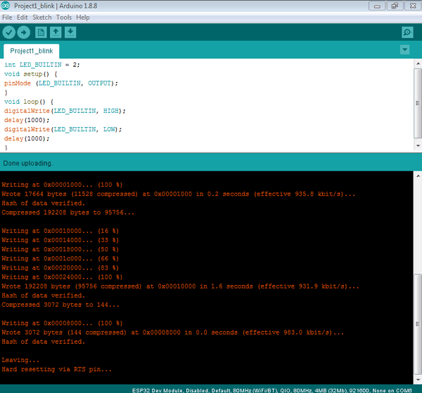
After uploading the code, you will see a window like this and finds “Done uploading” if everything you did earlier was correct.
Now see your ESP module and you will find that a LED of your module is blinking at an interval of 1 second. You can also connect LED externally with ESP32 in that case you have to just change that PIN to which you are connecting the LED.
Working of ESP32 LED Blinking Project
After going through the above steps properly, you can blink LED using ESP32, so here I am showing you some pictures to demonstrate how it is working:
This is how we can successfully blink LED using ESP32 with Arduino IDE. Complete code is given below. You can also connect the external LED with some GPIO pin of ESP32, just change the pin no. in the code.
I hope you liked the article and learned something new, if you have any questions regarding this project, please comment below.
int LED_BUILTIN = 2;
void setup() {
pinMode (LED_BUILTIN, OUTPUT);
}
void loop() {
digitalWrite(LED_BUILTIN, HIGH);
delay(1000);
digitalWrite(LED_BUILTIN, LOW);
delay(1000);
}


