


Do you know an internet time clock have a precision of 0.02 to 0.10 seconds? In this project we are going to make an ESP32 based internet clock to display the internet time over a 16x2 LCD display. The most used and popular protocol for synchronizing time over the internet is NTP (Network Time Protocol). The reference time is taken from a connected radio clock or atomic clock.
Here, we are going to fetch the time data from the internet using ESP32 controller. ESP32 is successor of popular ESP8266 Wi-Fi module, with many advanced features such as the module is a dual core 32-bit CPU with built-in Wi-Fi and dual-mode Bluetooth. We will use Arduino IDE to upload the code into ESP32 and for interfacing 16x2 LCD with ESP32 we are using I2C connector.
What is NTP (Network Time Protocol)?
NTP is a TCP/IP protocol used for synchronization of time between systems and Data networks. To synchronize computer clock times with extreme precision NTP uses Coordinated Universal Time, offering greater accuracy on smaller networks -- down to a single millisecond in a local area network. NTP relies on the host to account for time zones.
Some of the advantages of using NTP include:
- NTP can be easily deployed on servers hosting different services.
- NTP requires less resource overhead.
- NTP has minimal bandwidth requirements.
- NTP can handle hundreds of clients at a time with minimum CPU usage
Components Required
- ESP32
- 16*2 LCD display
- I2C LCD controller
- Jumpers
- Breadboard
Circuit diagram
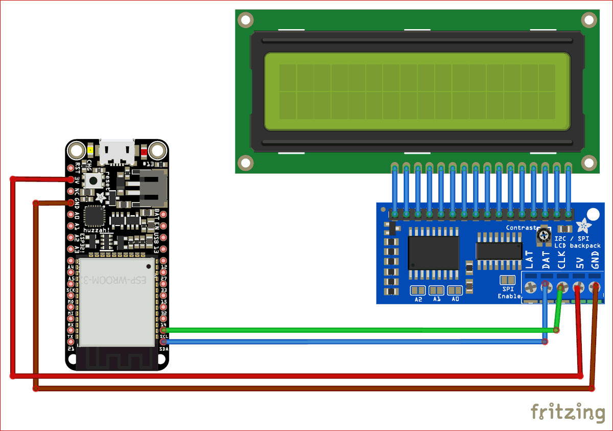
Connections for interfacing LCD with ESP32 is given below
- Connect pin 1-16 of I2C module to pin 1-16 of LCD display.
- SDA pin of I2C module -> SDA pin of ESP32 i.e D21
- SCL pin of I2C module -> SCL pin of ESP32 i.e D22
I have connected 3v of ESP32 to Vcc pin of I2C for demonstration only, but we need 5V supply for the I2C module to display data clearly. Because ESP32 can only give 3.3 volts which is low for the I2C module and data won’t be visible clearly. So, it’s better to use external 5V supply.
Programming Code Explanation
The complete code for ESP32 Internet Clock is given at the end of the article. Here we are explaining few important parts of code.
There are 3 libraries we need to install in Arduino IDE before we compile the code, the first one is for the I2C LCD. The 2nd library is for NTPClient, this library connects the ESP32 WiFi to a time server, the server sends time information to the module. And, the last one is Arduino Time library, this library converts Unix timestamp (Unix epoch) into: seconds, minutes, hours, day of the week, day, month and year.
Basically the time server sends time in Unix epoch format which needs to be converted.
Now, start with including all the libraries in the code:
#include <WiFi.h>
#include <WiFiUdp.h>
#include <NTPClient.h>
#include <TimeLib.h>
#include <LiquidCrystal_I2C.h>
Configure I2C LCD with 0x27 address, 16 columns and 2 rows, as shown in the below code:
LiquidCrystal_I2C lcd(0x27, 16, 2);
To connect with the time server NTPClient.h library is used and for sending and receiving UDP messages WiFiUdp.h library is used.
UDP is also a Protocol which send and receive short messages from our system to NTP server. So to get the time from Internet, we have to define three variables in our program for NTP.
NTP_OFFSET - defines the time zone of your country
NTP_INTERVAL - time required by NTP to update the time.
NTP_ADDRESS - defines NTP server of your country.
Now, in the below code, 'time.nist.gov' (default server) is used with +1 hour offset (3600 seconds) 60 seconds (60000 milliseconds) update interval
NTPClient timeClient(ntpUDP, "time.nist.gov", 3600, 60000);
In setup Function, initialize I2C LCD module by defining the SDA and DCL pins for I2C communication, (SDA = GPIO21, SCL = GPIO22)
lcd.begin(21, 22);
In loop function, we have used timeClient.update() function for taking updated time from NTP in form of string and stores it in formattedTime variable
   timeClient.update();
   unsigned long unix_epoch = timeClient.getEpochTime();
Display Internet Data on 16x2 I2C LCD
Get the complete code form the end and upload it into ESP32 using Arduino IDE.
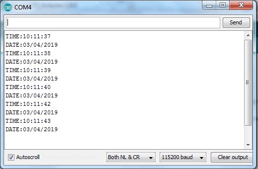
Then, open serial monitor to check if we are getting internet time over there or not. The serial monitor should look like the image given below:
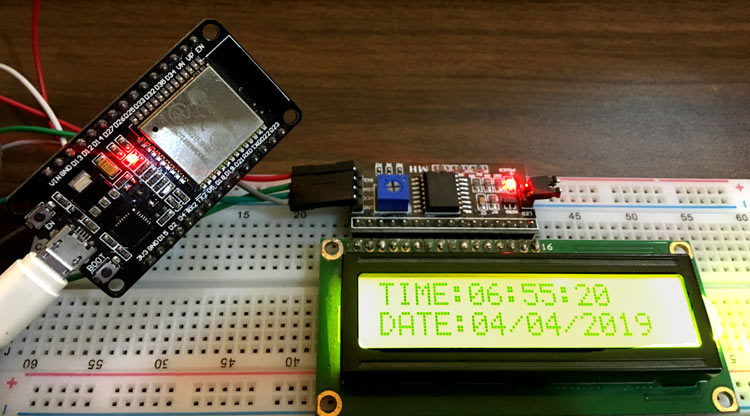
If this works fine you will definitely get internet time over the 16x2 I2C display and the hardware should look like this
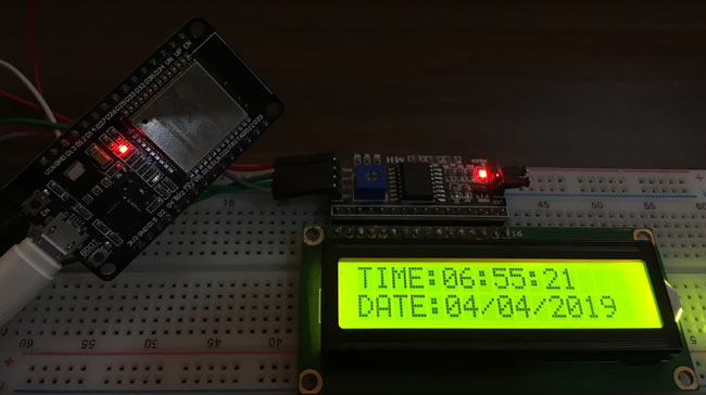
Hence, we have successfully fetch the internet time from the internet server using ESP32.
#include <WiFi.h>
#include <WiFiUdp.h>
#include <NTPClient.h> // Include NTPClient library
#include <TimeLib.h> // Include Arduino time library
#include <LiquidCrystal_I2C.h> // Include LiquidCrystal_I2C library
LiquidCrystal_I2C lcd(0x27, 16, 2); // Configure LiquidCrystal_I2C library with 0x27 address, 16 columns and 2 rows
const char *ssid = "CircuitLoop";
const char *password = "circuitdigest101";
WiFiUDP ntpUDP;
// 'time.nist.gov' is used (default server) with +1 hour offset (3600 seconds) 60 seconds (60000 milliseconds) update interval
NTPClient timeClient(ntpUDP, "time.nist.gov", 3600, 60000);
char Time[ ] = "TIME:00:00:00";
char Date[ ] = "DATE:00/00/2000";
byte last_second, second_, minute_, hour_, day_, month_;
int year_;
void setup() {
Serial.begin(115200);
lcd.begin(21, 22); // Initialize I2C LCD module (SDA = GPIO21, SCL = GPIO22)
lcd.backlight(); // Turn backlight ON
lcd.setCursor(0, 0);
lcd.print(Time);
lcd.setCursor(0, 1);
lcd.print(Date);
WiFi.begin(ssid, password);
Serial.print("Connecting.");
while ( WiFi.status() != WL_CONNECTED ) {
delay(500);
Serial.print(".");
}
Serial.println("connected");
timeClient.begin();
}
void loop() {
timeClient.update();
unsigned long unix_epoch = timeClient.getEpochTime(); // Get Unix epoch time from the NTP server
second_ = second(unix_epoch);
if (last_second != second_) {
minute_ = minute(unix_epoch);
hour_ = hour(unix_epoch);
day_ = day(unix_epoch);
month_ = month(unix_epoch);
year_ = year(unix_epoch);
Time[12] = second_ % 10 + 48;
Time[11] = second_ / 10 + 48;
Time[9] = minute_ % 10 + 48;
Time[8] = minute_ / 10 + 48;
Time[6] = hour_ % 10 + 48;
Time[5] = hour_ / 10 + 48;
Date[5] = day_ / 10 + 48;
Date[6] = day_ % 10 + 48;
Date[8] = month_ / 10 + 48;
Date[9] = month_ % 10 + 48;
Date[13] = (year_ / 10) % 10 + 48;
Date[14] = year_ % 10 % 10 + 48;
// Send time and date to serial monitor
Serial.println(Time);
Serial.println(Date);
// Display time and date on the 16x2 LCD
lcd.setCursor(0, 0);
lcd.print(Time);
lcd.setCursor(0, 1);
lcd.print(Date);
last_second = second_;
}
delay(200);
}


