


The RF module consists of a 433 MHz RF transmitter and receiver modules. These are ASK (Amplitude shift keying) or OOK (Of Hook Keying) type RF modules. While transmitting logic zero the transmitter fully suppresses the carrier frequency and hence consumes only low power in battery operation. When logic one is transmitted the transmitter is ON, and the carrier frequency is full and hence, there will be a high power supply that is in the range of about 4.5mA with a 3V power supply.
The transmitter and receiver are needed to be interfaced with microcontrollers for data transfer. The data is sent serially from the transmitter and is received by a tuned receiver. The RF transmitter receives serial data from a microcontroller and transmits it to the receiver through an antenna connected to the 4th pin of the transmitter. The receiver receives the data through an antenna and gives the data to the microcontroller connected to it.
These RF modules operate at a specific frequency of 433MHz. RF signals can travel between transmitter and receiver even when there is an obstruction. These modules are used for short range, low- budget, simplex-based communication. The low power consumption makes them ideal for battery- based implementations. It is used in various areas like Remote lighting controls, long-range RFID, wireless alarm and security systems etc. RF communication is used in Mobile communication and can have long rage communication and that’s what make them suitable for building IoT based applications. So here we are starting with a introductory Article about RF modules and how RF modules can be used with Arduino to send and receive data.
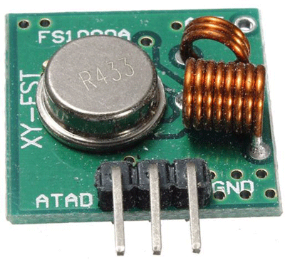
433 MHz RF Transmitter Module
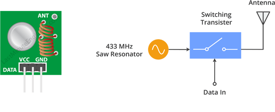
This small module is the RF transmitter. It is very simple. The SAW resonator which is tuned for 433.xx MHz operation is the heart of the module. There is a switching transistor and a few passive components on it.
When a logic HIGH is given as the DATA input, the oscillator is ON and produces a constant RF output carrier wave at 433.xx MHz and when the DATA input is logic LOW, the oscillator is OFF, so no carrier is produced. This technique is called Amplitude Shift Keying (ASK).
Specifications
- Working voltage: 3V – 12V
- Working current: max Less than 40mA, and min 9mA
- Resonance mode: (SAW)
- Modulation mode: ASK
- Working frequency: 433.92MHz
- Transmission power: 25mW
- Frequency error: +150kHz (max)
- Velocity: less than 10Kbps
- Transmission range: 90m (in open space)
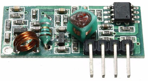
433 MHz RF Receiver Module
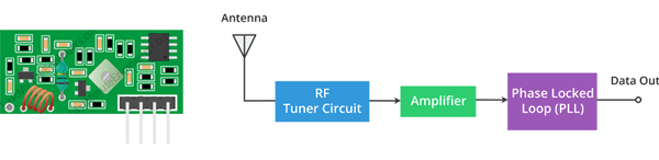
This is the RF receiver module. Even though it looks complex, it is as simple as the transmitter module. It consists of an RF tuner circuit, OP Amps, and a PLL. A couple of OP-Amps are used to amplify the carrier wave received from the transmitter. The amplified signal is then fed to a PLL (Phase Lock Loop) which enables the decoder to “lock” onto a stream of digital bits which gives better-decoded output and noise immunity.
Specifications
- Working voltage: 5.0VDC +0.5V
- Working current:≤5.5mA max
- Modulation mode: OOK/ASK
- Working frequency: 433.92MHz
- Bandwidth: 2MHz
- Sensitivity: exceeds –100dBm (50Ω)
Required Components
- Arduino Nano (2)
- RF 433MHz Transmitter Module
- RF 433MHz receiver module
- Potentiometer
- LED (5)
- Connecting wires
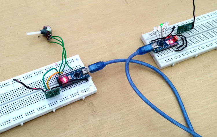
Circuit Diagram
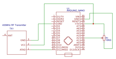
The circuit diagram for RF transmitter using Arduino Nano is given below. Here a potentiometer is connected to vary the values to be sent to receiver using the RF transmitter.
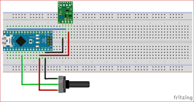
Below are the Pin connections details between RF transmitter and Arduino
- D12 pin of Arduino – DATA pin of RF transmitter
- VCC of Arduino – VCC of RF transmitter
- GND of Arduino – GND of RF transmitter
- GND of Arduino – first pin of the potentiometer
- A2 pin of Arduino – Second pin of the potentiometer
- VCC of Arduino – third pin of the potentiometer
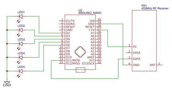
The circuit diagram for RF receiver using Arduino Nano is shown below. Here we have a series of LEDs. The LEDs are shifted based on the potentiometer values received by the receiver.
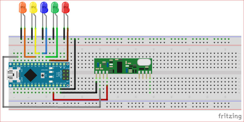
Below are the Pin connections details between RF receiver and Arduino
- D11 pin of Arduino - DATA pin of RF receiver.
- VCC of Arduino - VCC of RF receiver.
- GND of Arduino - GND of RF receiver.
- Positive leads of LEDs are connected to the digital pins D2, D3, D4, D5, and D6
- Negative leads of the LEDs are grounded.
Coding Explanation
Complete Arduino code for both RF transmitter and receiver side are given at the end of this tutorial, here we are explaining the complete program to understand the working of the project. But before starting with the code first we have to install one library in Arduino IDE.
Here we are using the virtual wire library. Download virtual wire library from the below link
VirtualWire is an Arduino library that provides the features to send short messages, without addressing, acknowledgment or retransmit. The messages are sent as a bit like UDP over wireless using ASK (amplitude shift keying). This library supports a number of inexpensive radio transmitters and receivers.
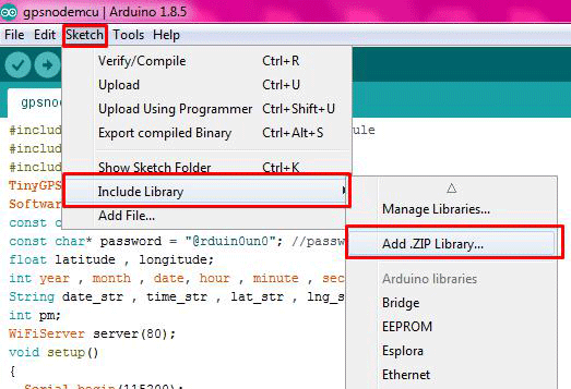
To add the library in Arduino IDE go to Sketch>>Include library>>Add .ZIP library then upload the library that you downloaded from the above link.
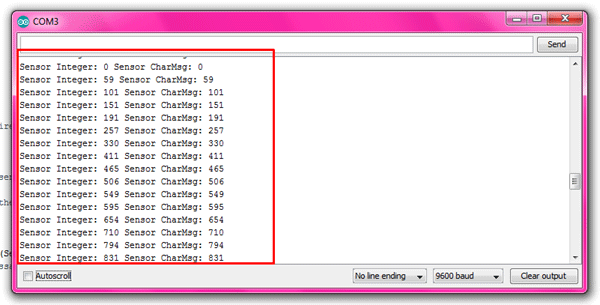
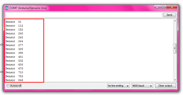
After uploading the program open serial monitor on both sides and you will see the outputs as shown below.
Output at the RF transmitter section shows the values of the potentiometer.
And output at the receiver shows the received sensor value. LEDs are shifted according to the range of the sensor values. Here we have given a range of 200 for each LED.
So this is how Arduino can be used in RF-based Communication, check more Arduino based IoT projects here.
Code for the RF Transmitter Section
#include <VirtualWire.h>
const int SensorPin = A2; // potentiometer pin
int SensorData;
char SensorCharMsg[5];
void setup()
{
pinMode(SensorPin,INPUT);
// for debugging
Serial.begin(9600);
// VirtualWire setup
vw_setup(2000); // Bits per sec
}
void loop()
{
// Read and store Sensor 1 data
SensorData = analogRead(SensorPin);
// Convert integer data to Char array directly
itoa(SensorData,SensorCharMsg,10);
// DEBUG
Serial.print("Sensor Integer: ");
Serial.print(SensorData); // print the sensor data
Serial.print(" Sensor CharMsg: ");
Serial.print(SensorCharMsg); //print the char array
Serial.println(" ");
delay(100);
// END DEBUG
vw_send((uint8_t *)SensorCharMsg, strlen(SensorCharMsg)); // send the message
vw_wait_tx(); // Wait until the whole message is gone
delay(200);
} // END void loop
Code for RF Receiver Section
#include <VirtualWire.h>
int SensorData; // Sensors
char SensorCharMsg[5]; // RF Transmission container
const int led1 = 2;
const int led2 = 3;
const int led3 = 4;
const int led4 = 5;
const int led5 = 6;
void setup()
{
Serial.begin(9600);
pinMode(led1, INPUT);
pinMode(led2, INPUT);
pinMode(led3, INPUT);
pinMode(led4, INPUT);
pinMode(led5, INPUT);
// VirtualWire
// Initialise the IO and ISR
// Required for DR3100
vw_set_ptt_inverted(true);
// Bits per sec
vw_setup(2000);
// Start the receiver PLL running
vw_rx_start();
} // END void setup
void loop()
{
uint8_t buf[VW_MAX_MESSAGE_LEN];
uint8_t buflen = VW_MAX_MESSAGE_LEN;
// Non-blocking
if (vw_get_message(buf, &buflen))
{
int i;
// Message with a good checksum received, dump it.
for (i = 0; i < buflen; i++)
{
// Fill SensorCharMsg Char array with corresponding
// chars from buffer.
SensorCharMsg[i] = char(buf[i]);
}
// Null terminate the char array
// This needs to be done otherwise problems will occur
// when the incoming messages has less digits than the
// one before.
SensorCharMsg[buflen] = '\0';
// Convert Sensor1CharMsg Char array to integer
SensorData = atoi(SensorCharMsg);
// DEBUG
Serial.print("Sensor ");
Serial.println(SensorData);
// END DEBUG
}
if (SensorData <= 200)
{
digitalWrite(led1, HIGH);
}
else
digitalWrite(led1, LOW);
if ( SensorData > 200 && SensorData <= 400)
{
digitalWrite(led2, HIGH);
}
else
digitalWrite(led2, LOW);
if ( SensorData > 400 && SensorData <= 600)
{
digitalWrite(led3, HIGH);
}
else
digitalWrite(led3, LOW);
if ( SensorData > 600 && SensorData <= 800)
{
digitalWrite(led4, HIGH);
}
else
digitalWrite(led4, LOW);
if ( SensorData > 800 && SensorData <= 1023)
{
digitalWrite(led5, HIGH);
}
else
digitalWrite(led5, LOW);
}


