


RF communication is one of the most used communication technique in IoT applications, and we previously used 433 MHz RF modules in communication between two Arduino. In this tutorial we will use NRF24L01 transceiver module to make wireless communication between Arduino board and NodeMCU. Here we will get the real-time Timestamp from the internet server using NodeMCU ESP8266 and transmit it wirelessly to Arduino uno via NRF24L01 transceiver and print it on 16x2 LCD display connected to Arduino Uno.
So the nRF24L01 module will be interfaced with ESP8266 at transmitter side and with Arduino Uno at receiver side.
Materials Used
- Arduino UNO R3
- NodeMCU
- NRF24L01 Transceiver Module
- 16*2 Alphanumeric LCD
- Connecting wires
- Breadboard
- Power supply
NRF24L01 Transceiver Module
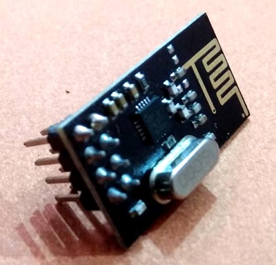
The nRF24L01 transceiver module is used in wireless communication between two microcontrollers. It operates in 2.4 GHz worldwide ISM frequency band and uses GFSK modulation for data transmission. The data transfer rate can be 250kbps, 1Mbps or 2Mbps. If it is used in open space without any obstacles and operated with lower baud rate its range can reach up to 100 meters.
The nRF24L01 Transceiver module communicates over a SPI Interface with a maximum data rate of 10Mbps. The SPI bus uses a concept of a Master and Slave. Here the SPI bus pins of the Arduino/NodeMCU can be connected to the SPI bus pins of NRF24L01 Transceiver module.
The nRF24L01 transceiver module transmits and receives data at a certain frequency band called as a channel. If multiple NRF24L01 transceiver modules have to communicate with each other, they must be configured as the same channel. This channel could be at any frequency in the 2.4 GHz ISM band. Each channel occupies a bandwidth of less than 1MHz. This gives us 125 channels with 1MHz bandwidth spacing. So, the NRF24L01 module can use 125 possible communication channels and it could be between 2.400 to 2.525 GHz.
What is 2.4 GHz ISM band?
2.4 GHz band is one of the Industrial, Scientific and Medical (ISM) bands reserved internationally for the use of unlicensed low-powered devices. Examples are NFC devices, Cordless phones and Bluetooth devices which use the ISM frequencies.
Technical specifications:
- 2.4Ghz licence-free ISM band.
- Highest data speed 2Mbps, high efficient GFSK modulation, anti-interfere, especially suits for industrial control.
- 125 channel, can reach different points or jump frequency communication needs.
- Low power consumption 1.9 – 3.6V, in standby mode it only need 1uA.
- Send and receive interruption signal, send 28 bytes maximum each time.
- Integrated special voltage regulator, use any kind of power including DC/DC power can have better communication effort.
- Two channels data receive, embedded circular antennas, communication distance is up to 100 meters in open and no interferes environment.
- Dimension: 39mm * 17mm * 1mm(PCB embedded antennas)
Pinout of nRF24L01:
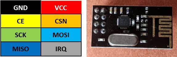
Pin description of nRF24L01:
GND: This is the ground reference pin.
VCC: This is the power supply pin of the module which can be powered from 1.9 to 3.9 volts. It can be connected to the 3.3V pin of the Arduino and NodeMCU module.
CE: It is the chip enable pin which is an active high pin. This pin mode decides whether the module is transmitting or receiving.
CSN: It stands for Chip Select Not, It is an active-LOW pin and is normally kept HIGH. When this pin goes low, the nRF24L01 begins listening on its SPI port for any incoming data.
SCK: It is the Serial Clock pin which accepts incoming clock pulses from the SPI master device.
MOSI: It stands for Master Out-Slave In. It is responsible for input to the NRF24L01 Trans-receiver module.
MISO: It stands for Master In-Slave Out. It is responsible for output from the NRF24L01 Trans-receiver module.
IRQ: This is an interrupt pin that can alert the master device when any new incoming data is available.
Circuit Diagram
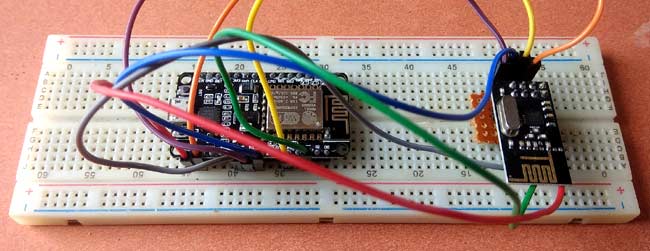
nRF24L01 Transmitter Side with NodeMCU ESP8266:
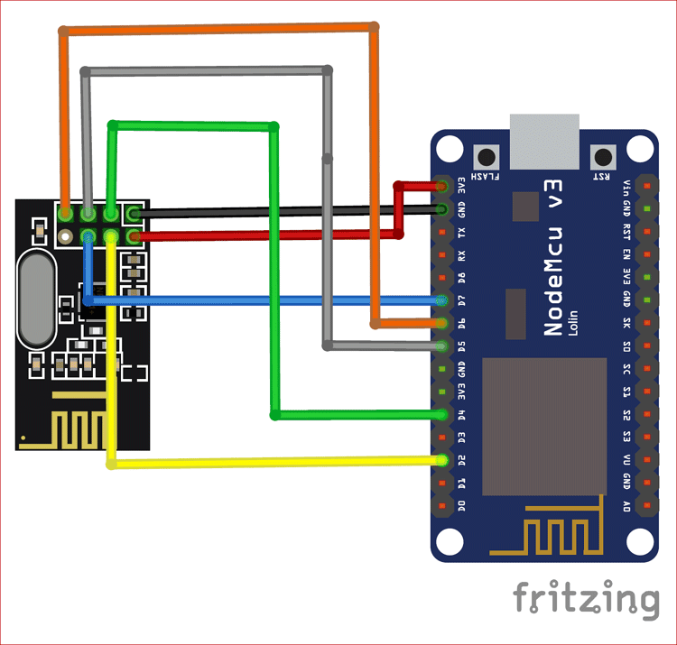
In the Transmitter side, the NodeMCU is module is connected to a NRF24L01 module which acts as the Transmitter. As shown in the figure the SPI Pins of the NodeMCU are connected to the SPI pins of the NRF24L01 module. Apart from these, CE and CSN pins are connected to digital output pins of the NodeMCU.
Below table shows the connections between nRF24L01 and NodeMCU:
|
NRF24L01 |
NodeMCU |
|
VCC |
3.3 |
|
GND |
GND |
|
CE |
D4 |
|
CSN |
D2 |
|
MOSI |
D7 |
|
MISO |
D6 |
|
SCK |
D5 |
Here at the transmitter side we get the current timestamp and date from inbuilt time library of ESP8266 using “pool.ntp.org” server. Then we can process this data to send to the receiver side wirelessly through the NRF24L01 module.
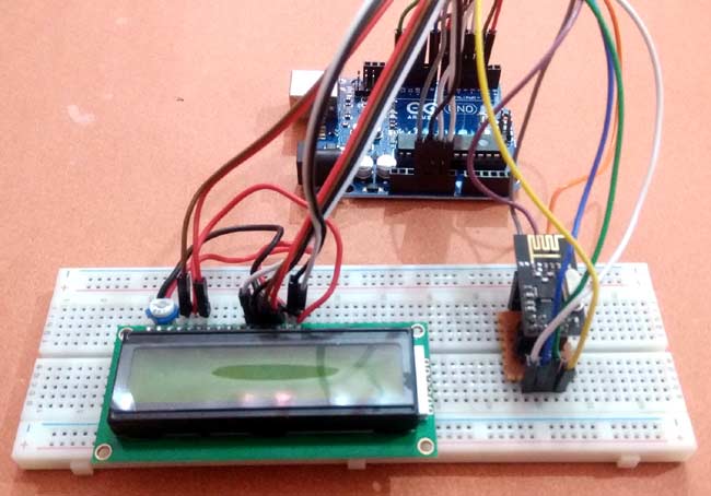
Receiver Side with Arduino Uno:
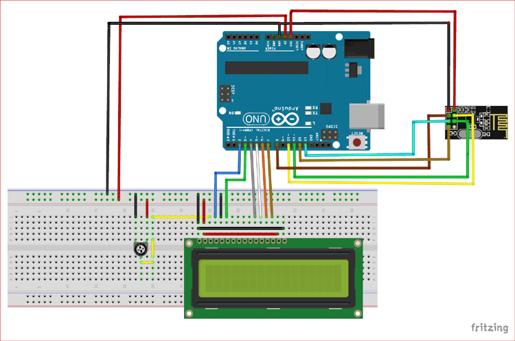
As shown in the figure above, we have connected NRF24L01 to Arduino Uno, here the SPI Pins of the NRF24L01 module are connected to the Arduino UNO board. The data pins and control pins of the LCD are also connected to digital pins of Arduino board. A potentiometer is connected to the LCD to change the contrast of LCD display.
Below table shows the connections between LCD and Arduino Uno:
|
LCD |
Arduino |
|
RS |
2 |
|
RW |
GND |
|
EN |
3 |
|
PIN 1 & 16 |
GND |
|
PIN 2 & 15 |
5V |
|
PIN 3 |
Variable Pin of Potentiometer |
|
PIN 11,12,13,14 |
4,5,6,7 |
Connections between NRF24L01and Arduino Uno:
|
NRF24L01 |
Arduino |
|
VCC |
3.3 |
|
GND |
GND |
|
CE |
8 |
|
CSN |
10 |
|
MOSI |
11 |
|
MISO |
12 |
|
SCK |
13 |
Programming Explanation
Complete programs for NRF24L01 ESP8266 receiver side and NRF24L01 Arduino Uno transmitter side are given at the end of this tutorial.
NodeMCU NRF24L01 Transmitter side:
The first step is to install and include all the dependent libraries which we are going to use in this project.
#include <RH_NRF24.h>
#include <ESP8266WiFi.h>
#include <time.h>
Here we have used RF_NRF24.h header file for the wireless NRF24L01 module. It can be downloaded from here. Similarly for using WiFi functionality in ESP8266 module we must have to include ESP8266WiFi library. As here we are going to find the current time and date, hence we also need to include the time library in program.
The next step is to define the credentials of the network to which the NodeMCU will be connected. So replace your network ssid and password in place of write_your_ssid and write_your_pass.
const char* ssid = "write_your_ssid";
const char* password = "write_your_pass";
The next step in our program is to define an object named nrf24 which defines the two connected pins of NodeMCU.That means we have connected CE and CSN of the NRF24L01 to the D4, D2 pins of NodeMCU respectively.
RH_NRF24 nrf24(2,4);
In this step we have configured the Wireless module initialisation commands like channel selection, transmission power, data rate and check them if they initialised perfectly without any error. Otherwise it will parse an error in the serial terminal.
  Serial.begin(9600);
  while (!Serial);
  if (!nrf24.init())
  Serial.println("initialization failed");
  if (!nrf24.setChannel(1))
  Serial.println("Channel set failed");
  if (!nrf24.setRF(RH_NRF24::DataRate2Mbps,RH_NRF24::TransmitPower0dBm))
  Serial.println("RF set failed");
  Serial.setDebugOutput(true);
Then set the NodeMCU in station mode by calling the function WiFi.mode(). After that we are calling WiFi.begin function to connect to the network using the given network credentials.
  WiFi.mode(WIFI_STA);
  WiFi.begin(ssid, password);
In the time library configTime function supports time zone definition is given in seconds. It takes time zone and daylight saving value as its parameter. We will also pass the server name as its argument from which we can get the current time which is "pool.ntp.org" and "time.nist.gov". As in India the time zone is UTC +5:30, hence in seconds we can write it as 5.30*3600 which can also be written as 11*1800. Here day light saving is not considered so it is taken as 0.
configTime(11*1800, 0, "pool.ntp.org", "time.nist.gov");
In the infinite loop we have called the time() function to get the current time and then converted it into a string variable. Then this string variable is get converted into a binary array as NRF24L01 transceiver only transmits data in binary format. Finally using nrf24.send() function we can transmit this binary array of time to the receiver side.
NRF24L01 Arduino Uno Receiver Side:
In the receiver side also, the first step is to include necessary library files and define the pins of Arduino board which will be connected to LCD display.
#include <RH_NRF24.h>
#include <LiquidCrystal.h>
LiquidCrystal lcd(3,2, 4, 5, 6, 7);
Next, we have created a new binary array with maximum RadioHead user message length that can be supported by this library and calculated its length using sizeof() library .
      String data=String((char*)buf);
      lcd.setCursor(0,0);
      lcd.print(data.substring(0,10));
      lcd.setCursor(11,0);
      lcd.print(data.substring(20,24));
      lcd.setCursor(0,1);
      lcd.print("Time:");
      lcd.setCursor(6,1);
      lcd.print(data.substring(11,19));
The final step is to print the received data in 16x2 LCD. But before that we have converted it into string as we have to substring the complete data to get time and date distinctly. For this, function data.substring() is called. The substring() method extracts the characters from the string, between two specified indices, and returns the new sub string.
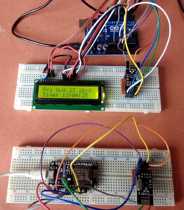
Note: Don’t forget to turn on your hotspot and Mobile data with turning on the power to the transmitter and receiver circuit.
So this is how Arduino and NodeMCU can communicate wirelessly using NRF24L01 module. Here the internet time is sent from NodeMCU to Arduino Uno using nRF24L01 and displayed on LCD at receiver side.
Complete codes for transmitter and receiver side along with a working video are given below.
Transmitter Side Code for ESP8266 NodeMCU:
#include <RH_NRF24.h>
#include <ESP8266WiFi.h>
#include <time.h>
const char* ssid = "gitargb";
const char* password = "gita@4321";
RH_NRF24 nrf24(2,4);
void setup()
{
Serial.begin(9600);
while (!Serial);
if (!nrf24.init())
Serial.println("initialization failed");
if (!nrf24.setChannel(1))
Serial.println("Channel set failed");
if (!nrf24.setRF(RH_NRF24::DataRate2Mbps, RH_NRF24::TransmitPower0dBm))
Serial.println("RF set failed");
Serial.setDebugOutput(true);
WiFi.mode(WIFI_STA);
WiFi.begin(ssid, password);
Serial.println("\nConnecting to WiFi");
while (WiFi.status() != WL_CONNECTED) {
Serial.print(".");
delay(1000);
}
configTime(11*1800, 0, "pool.ntp.org", "time.nist.gov");
Serial.println("\nWaiting for time");
while (!time(nullptr)) {
Serial.print(".");
delay(1000);
}
Serial.println("");
}
void loop()
{
Serial.println("Sending data to receiver");
time_t now = time(nullptr);
String timestring = String(ctime(&now));
uint8_t dataArray[timestring.length()];
timestring.getBytes(dataArray,timestring.length());
nrf24.send(dataArray,sizeof(dataArray));
nrf24.waitPacketSent();
delay(1000);
}
Receiver Side Code for Arduino uno:
#include <RH_NRF24.h>
#include <LiquidCrystal.h>
LiquidCrystal lcd(2,3, 4, 5, 6, 7);
RH_NRF24 nrf24;
void setup()
{
Serial.begin(9600);
while (!Serial) ;
if (!nrf24.init())
Serial.println("initialization failed");
if (!nrf24.setChannel(1))
Serial.println("Channel Set failed");
if (!nrf24.setRF(RH_NRF24::DataRate2Mbps, RH_NRF24::TransmitPower0dBm))
Serial.println("RF set failed");
lcd.begin(16, 2);
lcd.setCursor(0, 0);
lcd.print(" Welcome to ");
lcd.setCursor(0, 1);
lcd.print(" Circuit Digest ");
delay(1000);
lcd.clear();
}
void loop()
{
if (nrf24.available())
{
uint8_t buf[RH_NRF24_MAX_MESSAGE_LEN];
uint8_t len = sizeof(buf);
if(nrf24.recv(buf, &len))
{
Serial.print("Received: ");
Serial.println((char*)buf);
String data=String((char*)buf);
lcd.setCursor(0,0);
lcd.print(data.substring(0,10));
lcd.setCursor(11,0);
lcd.print(data.substring(20,24));
lcd.setCursor(0,1);
lcd.print("Time:");
lcd.setCursor(6,1);
lcd.print(data.substring(11,19));
}
else
{
Serial.println("recv failed");
}
}
}


