


A weather station is a device that can monitor various parameters like humidity, temperature, pressure, rainfall, etc. of the surrounding environment. We previously built a few weather stations using a different microcontroller like:
- IoT Based Raspberry Pi Weather Station
- IoT based ESP32 Wi-Fi Weather Station
- IoT Wireless Weather Station using Arduino
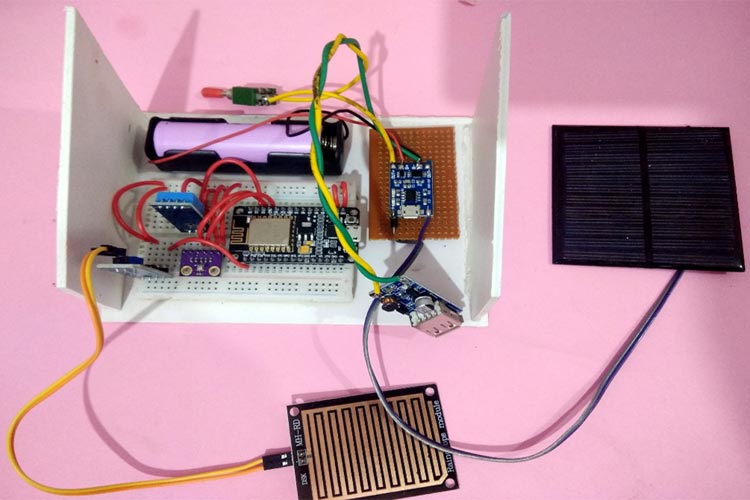
This time we are using ESP8266 NodeMCU as the main controller and a solar panel to power the complete setup. So this will be a self-sustained solar powered wireless weather station. It also uses 3.7V 18650 Li-ion Battery to power up the circuit, this lithium battery will be charged with Solar panel using TP4056 Li-ion charger module. Apart from this, it will have a DHT11 sensor to measure temperature & humidity, BMP280 sensor to measure Pressure and Rain sensor to detect rainfall. All the weather data will be recorded and saved on the ThingSpeak IoT cloud which can be monitored from anywhere in the world.
Components Required
- NodeMCU ESP8266
- DHT11 Temperature and Humidity Sensor
- BMP280 Pressure Sensor
- Rain sensor
- TP4056 Li-ion charger
- 3.7V 18650 Li-ion Battery
- 18650 Battery Holder
- DC-DC 0.9V-5V Step-Up Booster
- Solar Panel 6V, 100Ma
- 1N4007 Diode
- Breadboard
- Jumper Wires
Before going into details, let’s learn about different components and modules used in this solar-powered wireless weather station.
TP4056 Li-Ion Battery Charger Module
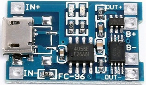
The TP4056 is a popular Lithium-Ion battery charger controller IC. It supports a constant current – constant voltage charging for a single cell 3.7v Li-Ion Battery. It comes with an 8-pin SOP package, which can be assembled with some external components to build a complete charging module.
The complete pin description of a TP4056 is shown below:

Charging a 3.7V Li-Ion battery using TP4056 Charger
To charge a 18650, 3.7V Li-ion battery using the TP4056 charging module, connect the circuit as per the schematics below.
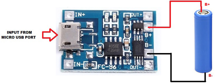
It can also be charged from a 5V DC input source using the micro USB cable and a mobile charger, etc. But in this Solar Wi-Fi Weather Station project, we are charging the battery using a solar PV module.
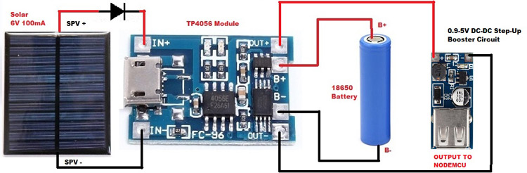
Charging the 18650 Li-ion battery from Solar Panel
Here the NodeMCU is powered from a solar panel. The output from the 18650 battery is (3.7-4) volts, which can’t be used to power the NodeMCU as it requires 5v to power up. So the output of the TP4056 Li-Ion charger is connected to a (0.9-5) V DC-DC step-up Booster circuit to boost the voltage to 5v.
BMP280 Pressure sensor
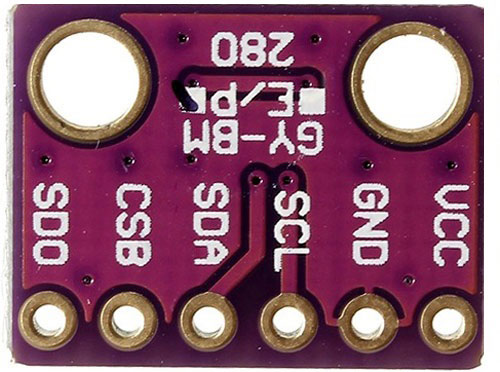
The BMP280 is an absolute barometric pressure sensor, which is suitable for mobile applications. It is very popular for its very compact dimensions and low power consumption. It is used in mobiles, smartwatches, weather stations, etc. The BMP280 is based on Bosch’s proven Piezo-resistive pressure sensor technology featuring high accuracy and linearity as well as long-term stability.
Features of BMP280:
- Pressure Range: 300-1100 hPa
- Temperature Range: -40-85°C
- Average typical current consumption:3.4 μA @ 1 Hz
- Interface: I2C and SPI
- Operating voltage: 1.71 V – 3.6 V
If you don’t have BMP280, then BMP180 can also be used to build an IoT weather station.
DHT11 Temperature and Humidity Sensor
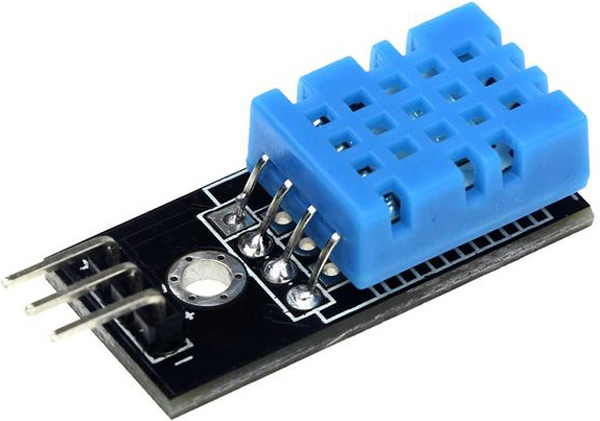
DHT11 is a sensor used to measure the temperature and humidity of the surrounding. DHT11 sensor comprises a capacitive humidity sensing element which is used to measure the humidity and an NTC thermistor for sensing the temperature. The humidity sensing capacitive element has two electrodes with a moisture-holding substrate as a dielectric between them. Change in the capacitance value occurs with the change in humidity levels. The circuit IC measures and processes these resistance values and changes them into a measurable digital signal.
Features:
- Operating Voltage: 3.3V-5.5V
- Temperature Range: 0-50 °C
- Temperature Accuracy: ±2% °C
- Humidity Range: 20-90% RH
- Humidity Accuracy: ±5% RH
We previously used the DHT11 sensor to build weather stations using Raspberry Pi, Arduino, and ESP8266.
Rain sensor
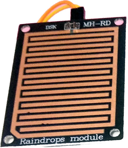
Rain sensor is used to detect rainfall. This is suitable for applications like automatic wipers, weather stations, etc. Rain sensor works on the concept of variable resistance. When the surface is dry, the two resistance coils are separated and resistance is very high. And in rainy conditions, the surface is wet and resistance is low (short circuit). This variable resistance is converted into variable voltage using a voltage divider network, and then this analog signal is fed to the LM393 Voltage comparator to convert it into a digital signal.
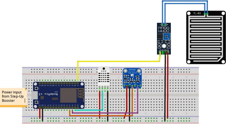
IoT Weather Station Circuit Diagram
The connection diagram for this solar-powered weather station is shown below.
Below table shows the connections between BMP280 sensor and NodeMCU
|
BMP280 |
NodeMCU |
|
VCC |
3.3V |
|
GND |
GND |
|
SCL |
D3 |
|
SDA |
D2 |
Below table shows the connections between the DHT11 sensor and NodeMCU
|
DHT11 |
NodeMCU |
|
1(VCC) |
3.3V |
|
2(Data) |
D1 |
|
3(GND) |
GND |
And this table shows the connections between Rain Sensor and NodeMCU
|
Rain sensor |
NodeMCU |
|
VCC |
3.3V |
|
AO |
A0 |
|
GND |
GND |
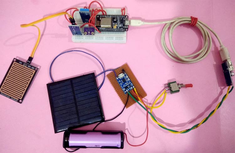
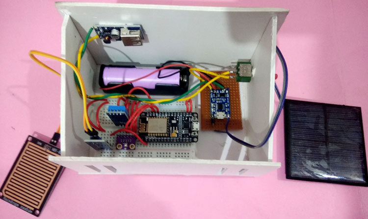
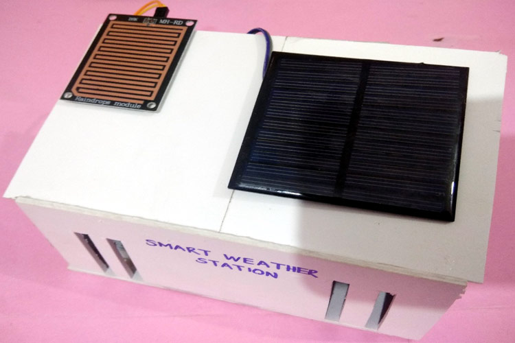
This is how the complete setup of IoT weather station looks:
Setup ThingSpeak Account Solar Weather Station
After successful completion of the hardware setup, now it’s time to setup the IoT platform, where all the weather data will be stored. Here we are using ThingSpeak to store the weather station parameters and show them in GUI. ThingSpeak is a very popular IoT cloud platform used to build store, monitor and process data online. We also used ThingSpeak to build many IoT based projects.
Follow the below steps to set up a ThingSpeak account.
Step 1: Sign up for ThingSpeak
First, go to https://thingspeak.com/ and create a new free Mathworks account if you don’t have a Mathworks account.
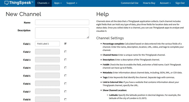
Step 2: Sign in to ThingSpeak
Sign in to ThingSpeak using your credentials and click on “New Channel”. Now fill up the details of the project like Name, Field names, etc. Here we have to create four field names such as Humidity, Temperature, pressure & Rain. Then click on “Save channel”.
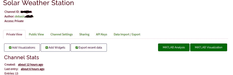
Step 3: Record the Credentials
Select the created channel and record the following credentials.
- Channel ID, which is at the top of the channel view.
- Write an API key, which can be found on the API Keys tab of your channel view.
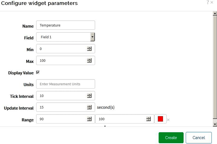
Step 4: Add widgets to your GUI
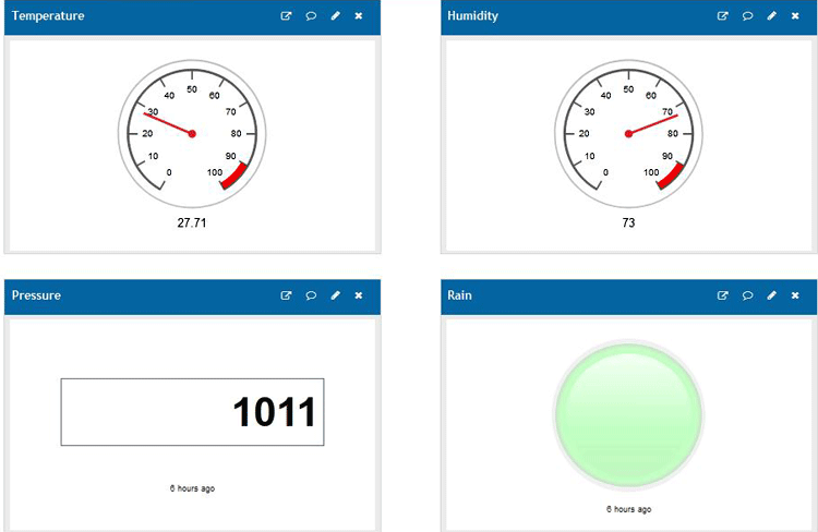
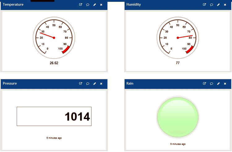
Click on “Add Widgets” and add four appropriate widgets like gauges, numeric displays, and indicators. In my case, I have taken gauges for displaying temperature and humidity, numeric display for pressure and Indicator for rain. Select appropriate field names for each widget.
Programming ESP8266 for Solar Powered Wi-Fi Weather Station
After the successful completion of the Hardware connections and ThingSpeak setup, now it’s time for programming the ESP8266 NodeMCU.
To upload code into NodeMCU using Arduino IDE, follow the steps below:
1. Open Arduino IDE, then go to File–>Preferences–>Settings.
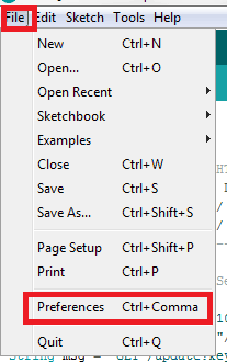
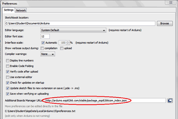
2. Type https://arduino.esp8266.com/stable/package_esp8266com_index.json in the ‘Additional Board Manager URL’ field and click ‘Ok’.
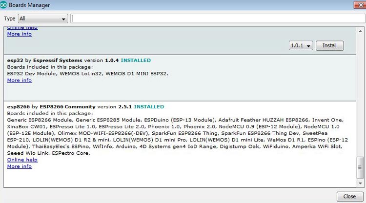
3. Now go to Tools > Board > Boards Manager. In the Boards Manager window, Type ESP8266 in the search box, select the latest version of the board and click on install.
4. After installation is complete, go to Tools ->Board -> and select NodeMCU 1.0(ESP-12E Module). Now you can program NodeMCU with Arduino IDE.
After the above setup for programming NodeMCU using Arduino IDE, upload the complete code into ESP8266 NodeMCU. The stepwise explanation of the complete code is given below.
Start the code by including all the required library files in the code like ESP8266WiFi.h for ESP8266 board, Wire.h for I2C communication, etc.
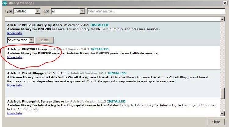
For including Adafruit_BMP280.h click on Sketch in Arduino IDE, then go to include library->Manage Libraries and search for Adafruit BMP280, from the list select the first search result and click on install.
Here, DHT.h is used for the DHT11 sensor, which can be downloaded from the link here. And ThingSpeak.h library is used for ThingSpeak platform, which can be added to Arduino IDE using the steps below:
- In the Arduino IDE, choose Sketch/Include Library/Manage Libraries.
- Click the ThingSpeak Library from the list, and click the Install button.
#include "ThingSpeak.h"
#include <ESP8266WiFi.h>
#include <Adafruit_BMP280.h>
#include "DHT.h"
Next, the I2C address of BMP280 is defined. The default address of BMP280 is 0x76. Then an object is defined for Adafruit_BMP280 class and also for DHT class.
#define BMP280_I2C_ADDRESS 0x76
Adafruit_BMP280 bmp280;
DHT dht;
Now, declare the network credentials- i.e. SSID and password. It is required to connect the NodeMCU to the internet.
const char* ssid     = "admin";//Replace with Network SSID
const char* password = "12345678";//Replace with Network Password
Next, declare the ThingSpeak account credentials such as the channel number and write API which was recorded earlier.
unsigned long ch_no = 1011111;//Replace with Thingspeak Channel no.
const char * write_api = "8YXXXXX";
Then I2C is initialized using function Wire.begin. Here GPIO4 (D2) is used as SDA and GPIO0 (D3) is used as SCL. DHT11 connection pin D1 is defined using dht.setup.
Wire.begin(4, 0);
dht.setup(D1);
To connect NodeMCU to the internet, call WiFi.begin and pass network SSID and password as its arguments. Check for the successful network connection using WiFi.status() and after a successful connection, print a message on LCD with IP address.
WiFi.begin(ssid, password);
while (WiFi.status() != WL_CONNECTED)
  {
    delay(500);
    Serial.print(".");
  }
  Serial.println("WiFi connected");
  Serial.println(WiFi.localIP());
Then connect to the ThingSpeak platform, using saved credentials using ThingSpeak.begin.
ThingSpeak.begin(client);
Next, the Temperature and Pressure values are decoded from BMP280 sensor using readTemperature() and readPressure(). The Pascal pressure value is converted into hpa.
float temp     = bmp280.readTemperature();
float pressure = bmp280.readPressure();
float hpa = pressure / 100;
Here humidity value is read from a DHT11 sensor using getHumidity() and rain values are received from the analog channel.
int humidity = dht.getHumidity();
int rain = analogRead(A0);
Finally, the fields of ThingSpeak cloud are assigned using setField() and data were sent to the cloud using writeFields().
ThingSpeak.setField(1, temp);
ThingSpeak.setField(2, humidity);
ThingSpeak.setField(3, hpa);
ThingSpeak.setField(4, rain);
ThingSpeak.writeFields(ch_no, write_api);
Now finally power up the circuit and upload the code in ESP8266. Then open the ThingSpeak website and you will see the Temperature and humidity values in gauge meter.
Complete code along with a Demonstration Video is given below.
#include "ThingSpeak.h"
#include <ESP8266WiFi.h>
#include <Adafruit_BMP280.h>
#include "DHT.h"
#define BMP280_I2C_ADDRESS 0x76
Adafruit_BMP280 bmp280;
DHT dht;
String stat = "";
const char* ssid = "admin";//Replace with Network SSID
const char* password = "12345678";//Replace with Network Password
unsigned long ch_no = 10xxxx;//Replace with Thingspeak Channel number
const char * write_api = "8YFxxxxxx";//Replace with Thingspeak write API
WiFiClient client;
void setup(void)
{
Serial.begin(9600);
delay(1000);
Wire.begin(4, 0);
dht.setup(D1);
if ( bmp280.begin(BMP280_I2C_ADDRESS) == 0 )
{
Serial.println("error");
while (1)
delay(1000);
}
WiFi.begin(ssid, password);
while (WiFi.status() != WL_CONNECTED)
{
delay(500);
Serial.print(".");
}
Serial.println("WiFi connected");
Serial.println(WiFi.localIP());
ThingSpeak.begin(client);
}
void loop()
{
float temp = bmp280.readTemperature();
float pressure = bmp280.readPressure();
float hpa = pressure / 100;
delay(dht.getMinimumSamplingPeriod());
int humidity = dht.getHumidity();
int rain = analogRead(A0);
ThingSpeak.setField(1, temp);
ThingSpeak.setField(2, humidity);
ThingSpeak.setField(3, hpa);
ThingSpeak.setField(4, rain);
ThingSpeak.writeFields(ch_no, write_api);
delay(10000);
}


