


Robots are used in many sectors like construction, military, manufacturing, assembling, etc. Robots can be autonomous or semi-autonomous. Autonomous robots do not require any human intervention and can act on their own according to the situation. Semi-autonomous robots work according to instructions given by humans. These semi-autonomous can be controlled by remote, phone, gestures, etc. We previously built few IoT based robots, which can be controlled from the webserver.
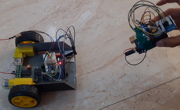
In today’s article, we are going to build a gesture-controlled robot using Arduino, MPU6050 Accelerometer, nRF24L01 Transceiver pair, and L293D motor driver module. We will design this robot into two parts. One is the Transmitter, and the other is the Receiver. Transmitter section consists of an Arduino Uno, MPU6050 Accelerometer and Gyroscope, and nRF24L01 while the Receiver section consists of an Arduino Uno, nRF24L01, two DC motors and L293D motor driver. The transmitter will act as remote to control the Robot where the robot will move according to the gestures.
Components Required
- Arduino Uno (2)
- NRF24L01 (2)
- MPU6050
- DC Motor (2)
- L293D Motor Driver Module
- Battery
MPU6050 Accelerometer and Gyroscope
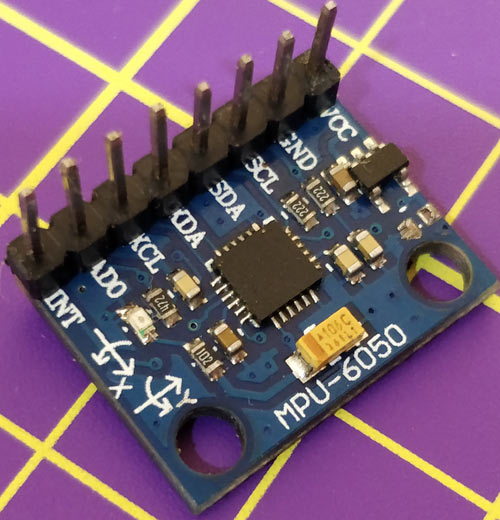
The MPU6050 sensor module is a complete 6-axis (3-axis Accelerometer and 3-axis Gyroscope) Micro-Electro-Mechanical System. MPU6050 sensor module also has an on-chip temperature sensor. It has an I2C bus and Auxiliary I2C bus interface to communicate with the microcontrollers and other sensor devices like 3-axis Magnetometer, Pressure sensor, etc.
The MPU6050 sensor module is used to measure acceleration, velocity, orientation, displacement, and some other motion-related parameters. This sensor module also has an inbuilt Digital Motion Processor that can perform complex calculations.
NRF24L01 Transceiver Module
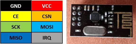
nRF24L01 is a single-chip radio transceiver for the worldwide 2.4 - 2.5 GHz ISM band. The transceiver consists of a fully integrated frequency synthesizer, a power amplifier, a crystal oscillator, a demodulator, modulator, and Enhanced ShockBurs protocol engine. Output power, frequency channels, and protocol setup are easily programmable through an SPI interface.
The operating voltage range of this Transceiver module is 1.9V to 3.6V. It has Built-in Power Down and Standby modes that make it power-saving and easily realizable.
Working of Hand Gesture controlled Robot using Arduino
To understand the working of this Arduino gesture control car, let us divide this project into two parts. The first part is the transmitter part (remote) in which the MPU6050 Accelerometer sensor continuously sends signals to the receiver (Robot) through Arduino and nRF transmitter.
The second part is the Receiver part (Robot car) in which the nRF receiver receives the transmitted data and sends it to Arduino, which further processes them and move the robot accordingly.
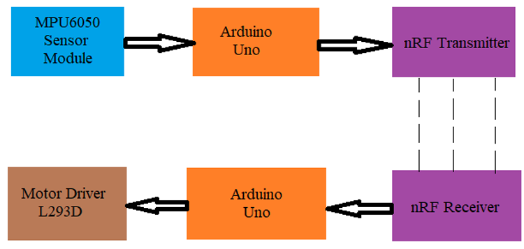
The MPU6050 Accelerometer sensor reads the X Y Z coordinates and sends the coordinates to the Arduino. For this project, we need only X and Y coordinates. Arduino then checks the values of coordinates and sends the data to the nRF Transmitter. The transmitted data is received by the nRF Receiver. The receiver sends the data to the receiver side’s Arduino. Arduino passes the data to the Motor Driver IC and the motor driver turns the motors in the required direction.
Circuit Diagram
This Hand Gesture controlled Robot using Arduino hardware is divided into two sections
1. Transmitter
2. Receiver
Transmitter Circuit for Arduino Gesture Controlled Car
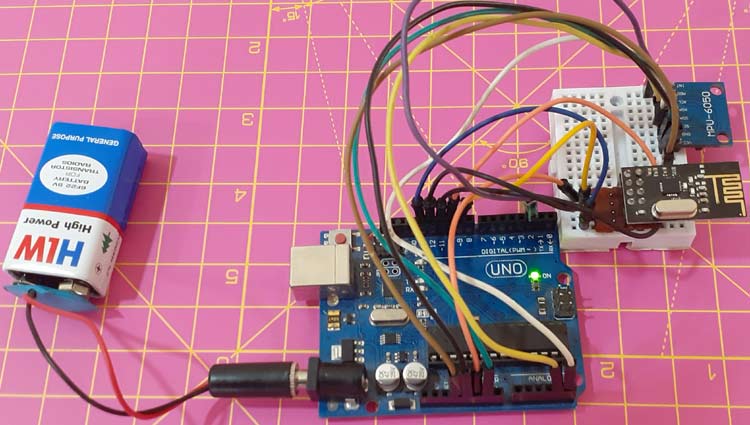
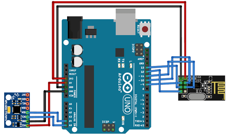
The transmitter section of this project consists of MPU6050 Accelerometer and Gyroscope, nRF24L01Transceiver, and Arduino Uno. The Arduino continuously gets data from the MPU6050 and sends this data to the nRF Transmitter. RF transmitter transmits the data into the environment.
The circuit diagram for the Transmitter section is given below.
|
nRF24L01 |
Arduino Uno |
|
VCC |
3.3V |
|
GND |
GND |
|
CE |
Pin 9 |
|
CSN |
Pin10 |
|
SCK |
Pin 13 |
|
MOSI |
11 |
|
MISO |
12 |
|
MPU6050 |
Arduino Uno |
|
VCC |
5V |
|
GND |
GND |
|
SCL |
Pin A5 |
|
SDA |
Pin A4 |
|
INT |
Pin 2 |
Receiver Circuit for Arduino Gesture Controlled Car
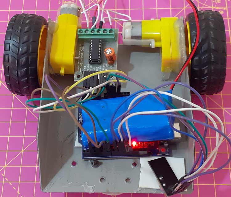
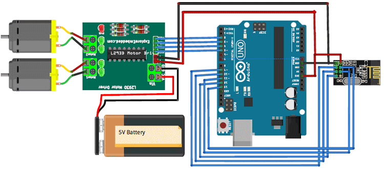
The receiver section of this gesture controlled robot consists of Arduino Uno, nRF24L01 Transceiver, 2 DC motors, and Motor driver module. NRF24L01 receiver receives the data from the transmitter and sends it to Arduino. Then according to received signals, Arduino moves the DC motors. The circuit diagram for the Receiver section is given below.
|
nRF24L01 |
Arduino Uno |
|
VCC |
3.3V |
|
GND |
GND |
|
CE |
Pin 9 |
|
CSN |
Pin10 |
|
SCK |
Pin 13 |
|
MOSI |
11 |
|
MISO |
12 |
|
Motor Driver |
Arduino Uno |
|
VCC |
5V |
|
GND |
GND |
|
INP A1 |
2 |
|
INP A2 |
3 |
|
INP B1 |
4 |
|
INP B2 |
5 |
Program Explanation
Complete code for this Gesture controlled robot using Arduino is given at the end of the document. Here we are explaining the program line by line.
Transmitter Side Program
In this program, Arduino reads the data from MPU6050 and sends it to nRF 24L01 transmitter.
Begin the program by adding the required library files. You can download the library files from the given links.
SPI.h
nRF24L01.h
Wire.h
MPU6050.h
#include <SPI.h>
#include <nRF24L01.h>
#include <RF24.h>
#include "Wire.h"
#include "I2Cdev.h"
#include "MPU6050.h"
Then define the variables for MPU6050 Gyroscope and Accelerometer data. Here only Accelerometer data will be used.
MPU6050 mpu;
int16_t ax, ay, az;
int16_t gx, gy, gz;
Define the Radio pipe addresses for the communication and nRF transmitters CN and CSN pins.
const uint64_t pipeOut = 0xE8E8F0F0E1LL;
RF24 radio(9, 10);
Inside the void setup() function, begin the serial monitor. And also initialize the wire and radio communication. radio.setDataRate is used to set the data transmission rate.
void setup()
{
  Serial.begin(9600);
  Wire.begin();
  mpu.initialize();
 radio.begin();
  radio.setAutoAck(false);
  radio.setDataRate(RF24_250KBPS);
  radio.openWritingPipe(pipeOut);
}
Read the MPU6050 sensor data. Here we are only using X and Y direction accelerometer data.
mpu.getMotion6(&ax, &ay, &az, &gx, &gy, &gz);
data.X = map(ax, -17000, 17000, 0, 255 );
data.Y = map(ay, -17000, 17000, 0, 255);
Finally, transmit the sensor data using radio.write function.
radio.write(&data, sizeof(MyData));
Receiver Side Program
As usual, start the program by including the required library files.
#include <SPI.h>
#include <nRF24L01.h>
#include <RF24.h>
Define the Radio pipe addresses for the communication and nRF transmitters CN and CSN pins.
const uint64_t pipeIn = 0xE8E8F0F0E1LL;
RF24 radio(9, 10);
Define the left and right DC motor pins.
const int IN1 = 2;
const int IN2 = 3;
const int IN3 = 4;
const int IN4 = 5;
Now check if the radio is available or not. If it is, then read the data.
if ( radio.available() ) {
    radio.read(&data, sizeof(MyData));
Now compare the received data and drive the motors according to the conditions.
if (data.Y < 80) { //Reverse
      digitalWrite(IN1, HIGH);
      digitalWrite(IN2, LOW);
      digitalWrite(IN3, LOW);
      digitalWrite(IN4, HIGH);
    }
……………
……………
……………
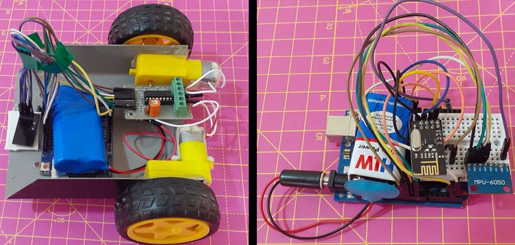
Testing the Hand Gesture controlled Robot using Arduino
Once the hardware is ready, connect both the transmitter and receiver side Arduinos to your laptop and upload the code. Then move the MPU6050 accelerometer to control the robot Car.
The complete working of the Gesture controlled robot can be found in the video given below.
Transmitter Side Program
#include <SPI.h>
#include <nRF24L01.h>
#include <RF24.h>
#include "Wire.h"
#include "I2Cdev.h"
#include "MPU6050.h"
//Define variables for Gyroscope and Accelerometer data
MPU6050 mpu;
int16_t ax, ay, az;
int16_t gx, gy, gz;
const uint64_t pipeOut = 0xE8E8F0F0E1LL;
RF24 radio(9, 10); // CN and CSN pins of nrf
struct MyData {
byte X;
byte Y;
};
MyData data;
void setup()
{
Serial.begin(9600);
Wire.begin();
mpu.initialize();
radio.begin();
radio.setAutoAck(false);
radio.setDataRate(RF24_250KBPS);
radio.openWritingPipe(pipeOut);
}
void loop()
{
mpu.getMotion6(&ax, &ay, &az, &gx, &gy, &gz);
data.X = map(ax, -17000, 17000, 0, 255 ); //Send X axis data
data.Y = map(ay, -17000, 17000, 0, 255); //Send Y axis data
delay(50);
radio.write(&data, sizeof(MyData));
Serial.print("Axis X = ");
Serial.print(data.X);
Serial.print(" ");
Serial.print("Axis X = ");
Serial.println(data.X);
}
Receiver Side Program
#include <SPI.h>
#include <nRF24L01.h>
#include <RF24.h>
const uint64_t pipeIn = 0xE8E8F0F0E1LL;
RF24 radio(9, 10);
// Left & Right motor pins
const int IN1 = 2;
const int IN2 = 3;
const int IN3 = 4;
const int IN4 = 5;
struct MyData {
byte X;
byte Y;
};
MyData data;
void setup()
{
Serial.begin(9600);
radio.begin();
radio.setAutoAck(false);
radio.setDataRate(RF24_250KBPS);
radio.openReadingPipe(1, pipeIn);
radio.startListening();
}
void recvData()
{
if ( radio.available() ) {
radio.read(&data, sizeof(MyData));
if (data.Y < 80) { //Reverse
digitalWrite(IN1, HIGH);
digitalWrite(IN2, LOW);
digitalWrite(IN3, LOW);
digitalWrite(IN4, HIGH);
}
if (data.Y > 145) {//forward
digitalWrite(IN1, LOW);
digitalWrite(IN2, HIGH);
digitalWrite(IN3, HIGH);
digitalWrite(IN4, LOW);
}
if (data.X > 155) {//right turn
digitalWrite(IN1, LOW);
digitalWrite(IN2, HIGH);
digitalWrite(IN3, LOW);
digitalWrite(IN4, HIGH);
}
if (data.X < 80) {//left turn
digitalWrite(IN1, HIGH);
digitalWrite(IN2, LOW);
digitalWrite(IN3, HIGH);
digitalWrite(IN4, LOW);
}
if (data.X > 100 && data.X < 170 && data.Y > 80 && data.Y < 130) { //stop car
digitalWrite(IN1, LOW);
digitalWrite(IN2, LOW);
digitalWrite(IN3, LOW);
digitalWrite(IN4, LOW);
}
}
}
void loop()
{
recvData();
Serial.print("X: ");
Serial.print(data.X);
Serial.print(" ");
Serial.print("Y: ");
Serial.print(data.Y);
Serial.print("\n");
}


