


You may have seen many conventional digital notice boards where one has to update the displayed information by manually changing the message using a keyboard or some other tool. But these notice boards can easily be converted into a wireless notice board, one such way is to use Bluetooth. By integrating the Bluetooth, the information on the LED panel can be updated wirelessly through our smartphone. Here HC05 Bluetooth module is connected to Arduino Uno which receives the data sent from the smartphone application. Then Arduino will process the data and display the information on the LED board.
Arduino and Bluetooth are commonly used in building any IoT based application, you can find some useful Arduino based IoT projects by following the link.
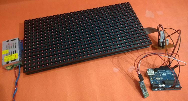
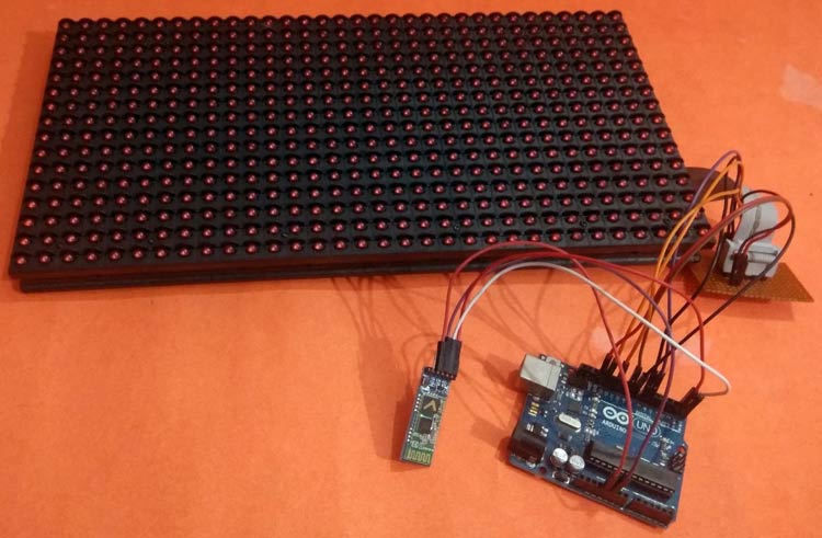
Materials Used
- 32*16 P10 LED module-1
- Arduino UNO-1
- HC05 Bluetooth module -1
- 5V,3 AMP SMPS -1
- 16 Pin FRC connector -1
- Connecting wires
- Jumpers
P10 LED Matrix Display Module
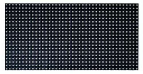
P10 is a 32*16 LED Matrix module which is popular for displaying big advertisements. There are 512 high-intensity LEDs in each unit of the P10 LED Module which consists, 32 LEDs in each row and 16 LEDs in each column.
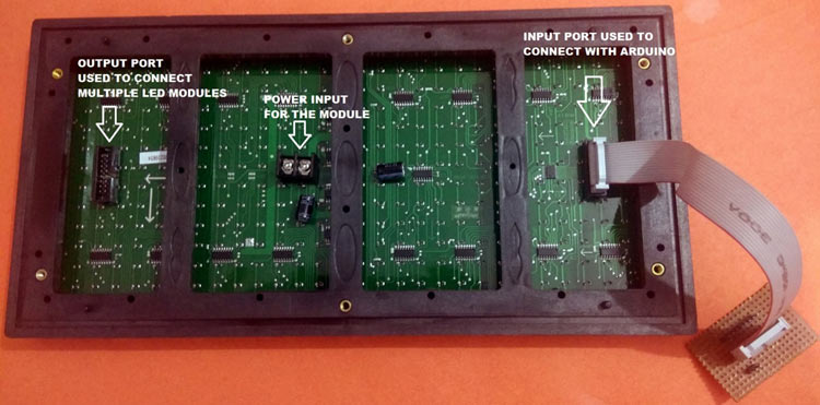
P10 LED modules can be multiplexed to build a bigger size display. There are two ports in a P10 module- input and output port. An input port is used for the incoming data from the Arduino side and the output port is used to connect the module to another LED P10 module.
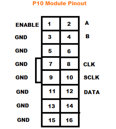
Pin Description of P10 LED Module:
- Enable: This pin is used to control the brightness of the LED panel, by giving a PWM pulse to it.
- A, B: These are called multiplex select pins. They take digital input to select any multiplex rows.
- Shift clock (CLK), Store clock (SCLK) and Data: These are the normal shift register control pins. Here a shift register 74HC595 is used.
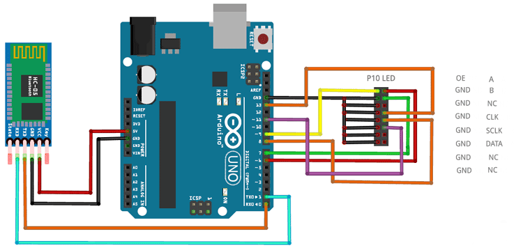
Connection Diagram
Complete circuit diagram for P10 module with Arduino and Bluetooth module is given below:
Programming the Arduino for P10 LED Display Board
Complete code for this Wireless notice board using Bluetooth module and Arduino is given at the end of the tutorial, here we are explaining the code in detail.
First, download and install the DMD.h and TimerOne.h library from the given links and then include all the required libraries in your code. Also, include the “Arial Black font” library for the text font which will be displayed on the LED board.
#include <SPI.h>
#include <DMD.h>
#include <TimerOne.h>
#include "SystemFont5x7.h"
#include "Arial_black_16.h"
In the next step, define the number of rows and columns, here we are using only one module, so ROW value and COLUMN value will be 1.
#define ROW_MODULE 1
#define COLUMN_MODULE 1
DMD p10 (ROW_MODULE, COLUMN_MODULE);
Then define all the variables which will be used throughout the program. Here you can see two Arrays, one for storing the notice board message and the other is for a welcome message (Welcome to IoT Design).
char message[200];
char char_read;
byte pos_index = 0;
int i;
char welcome_screen[] = "Welcome to IoT Design";
A Function p10scan() is written to check the incoming data from the Arduino side through the SPI Terminals. If it receives any data then it will trigger an interrupt pin for doing certain events.
void p10scan()
{
  p10.scanDisplayBySPI();
}
Inside setup(), we have initialized the timer and attached the interrupt to the function p10scan(). First, clear the screen using the function clearScreen(true) to turn off all the pixels on the LED board. Next copy the welcome_screen array to the message array by using strcpy function to display the welcome message until we give any message via Bluetooth application.
void setup()
{
   Timer1.initialize(2000);
   Timer1.attachInterrupt(p10scan);
   p10.clearScreen( true );
   Serial.begin(9600);
   strcpy(message,welcome_screen);
}
Inside the infinite loop, write a code to receive the message sent from the Bluetooth application. So, whenever the function Serial.available() is greater than 0, that means there is some data present at the serial terminal. Then copy the received message to the array.
if(Serial.available())
   {
        for(i=0; i<199; i++)
        {
            message[i] = '\0';
            Serial.print(message[i]);
        }
        pos_index=0;
    }
    while(Serial.available() > 0)
    {
       p10.clearScreen( true );
       if(pos_index < (199))
       {
           char_read = Serial.read();
           message[pos_index] = char_read;
           pos_index++;
       }
   }
To display a string on the LED matrix module in the desired font, use selectFont() function and use drawMarquee() function to print the string “Welcome to IoT Design”.
p10.selectFont(Arial_Black_16);
 p10.drawMarquee(message ,200,(32*ROW_MODULE)-1,0);
Finally to make the text scrolling, shift the whole message from Right to Left directions using a certain time period.
long start=millis();
   long timer_start=start;
   boolean flag=false;
   while(!flag)
   {
     if ((timer_start+30) < millis())
     {
       flag=p10.stepMarquee(-1,0);
       timer_start=millis();
     }
   }
This is how a Wireless Notice board using Bluetooth and Arduino can be built to display the advertisements on P10 LED display board.
Complete code and the demonstration video are given below.
#include <SPI.h>
#include <DMD.h>
#include <TimerOne.h>
#include "SystemFont5x7.h"
#include "Arial_black_16.h"
#define ROW_MODULE 1
#define COLUMN_MODULE 1
DMD p10(ROW_MODULE, COLUMN_MODULE);
char message[200];
char char_read;
byte pos_index = 0;
int i;
char welcome_screen[] = "Welcome to IoT Design";
void p10scan()
{
p10.scanDisplayBySPI();
}
void setup()
{
Timer1.initialize(2000);
Timer1.attachInterrupt(p10scan);
p10.clearScreen( true );
Serial.begin(9600);
strcpy(message,welcome_screen);
}
void loop()
{
if(Serial.available())
{
for(i=0; i<199; i++)
{
message[i] = '\0';
Serial.print(message[i]);
}
pos_index=0;
}
while(Serial.available() > 0)
{
p10.clearScreen( true );
if(pos_index < (199))
{
char_read = Serial.read();
message[pos_index] = char_read;
pos_index++;
}
}
p10.selectFont(Arial_Black_16);
p10.drawMarquee(message ,200,(32*ROW_MODULE)-1,0);
long start=millis();
long timer_start=start;
boolean flag=false;
while(!flag)
{
if ((timer_start+30) < millis())
{
flag=p10.stepMarquee(-1,0);
timer_start=millis();
}
}
}


