


In our previous articles, we have controlled LED with Adafruit IO using Raspberry Pi. Here we will explain How to Control Home Appliances with Adafruit IO dashboard and Raspberry Pi. Adafruit IO is a cloud service using which you can upload, display and monitor your data over the internet, and make your project IoT enabled. You can control motors, read sensor data, and make cool IoT applications over the internet using Adafruit IO. For test and try, with some limitation, Adafruit IO is free to use.
Components Required
- Raspberry Pi
- Lamp
- Realy
- Jumper Wires
- Adafruit IO
Relay
Relay is an electrically operated switch used to control many circuits by one signal. Relay is controlled or triggered by a small current and used to switch larger current. Generally relay has 5 terminals as shown below:
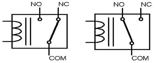
When no voltage is applied to the coil, COM terminal will be connected to NC (normally closed) terminal. And, when a voltage is applied to the coil, an electromagnetic field is generated that attracts the armature and connect COM terminal with NO (normally open) which allows much larger current to flow.
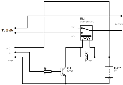
A small Driver circuit that consist a Transistor, Diode and a resistor is used to configure the relay. Where the transistor is used to amplify the current and resistor is used to provide biasing voltage to transistor. In case when the transistor is Off, Diode is used to prevent the relay from reverse current flow. Here, in this project we have used 6V Relay module.
Circuit Diagram
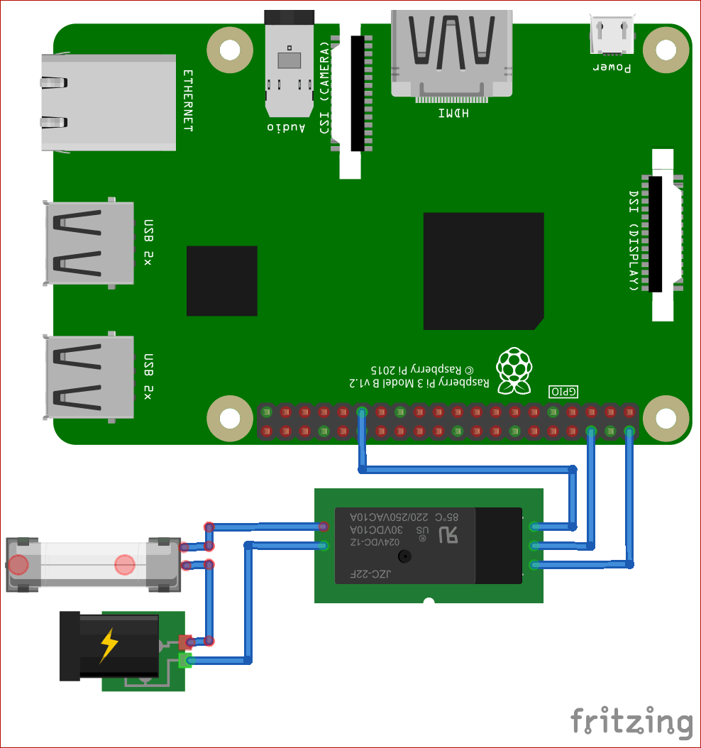
Raspberry Pi’s Vcc is connected to the Relay's Vcc. Connect the Raspberry's GND to the Relay's GND and Connect the Raspberry Pi’s GPIO5 to the Relay's IN.
Step 1 Adafruit IO Setup for Raspberry Pi
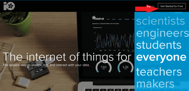
1. For Adafruit IO setup the first thing you will need to do is to sign up to Adafruit IO. To sign up go to Adafruit IO’s site https://io.adafruit.com and click on ‘Get started for Free’ on top right of the screen.
2. After this a window will pop up where you need to fill your details
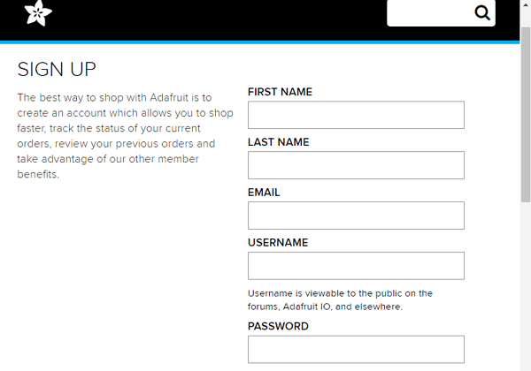
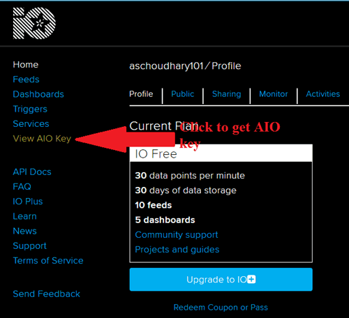
In sign up window fill your details like: your name, mail id, username etc. Then click on save settings and your account is created. To get your AIO key click on ‘View AIO Key’.
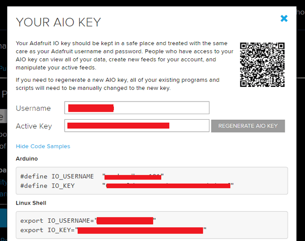
3. A window will pop up with your Adafruit IO AIO Key. Copy this key you'll need it later in your python code.
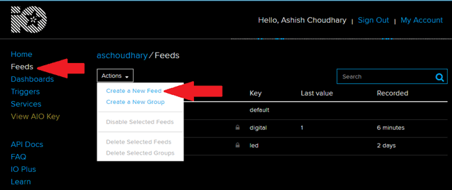
4. Now after this you need to create a feed. To create a feed click on ‘Feed’. Then click on ‘Actions’, you will see some options from them click on ‘Create a New Feed’.
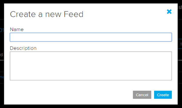
5. After this a new window will open where you need to input:
Name – In name option write a short descriptive name of your feed. You can use Letters, numbers, and spaces.
Description - A long form description of your data. This field is not required, but you can write a description about your data.
6. Click on ‘Create’, you will then be redirected to your new feed.
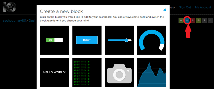
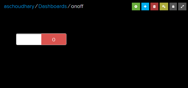
7. Next, to add a new Toggle Block you need to create a dashboard. Creating a Dashboard is same as Feed. So follow the same steps. Now to add block click on ‘Plus sign’ on top right corner of the screen and click on first option.
8. Name the block whatever you like, and set On Text to a value of 1 and Off Text to a value of 0. Make sure you have selected the Digital feed as the data source for the toggle.
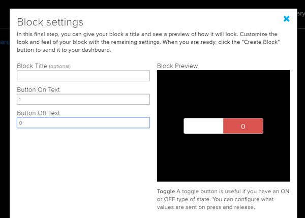
9. When you finished click on ‘Create Block’ to create your block.
Step 2 Raspberry Pi Setup with Adafruit IO
First update your Raspberry Pi using below commands:
sudo apt-get update
sudo apt-get upgrade
And
sudo pip3 install --upgrade setuptools
Now install the Raspberry Pi GPIO library
pip3 install RPI.GPIO
Install Adafruit Blinka library using this command:
pip3 install adafruit-blinka
Then using the following command install the Adafruit IO library
pip3 install adafruit-io
Now, download the adafruit/io-client-python repository by using:
git clone https://github.com/adafruit/io-client-python.git
Now go to the examples folder using:
cd io-client-python/examples/basics/
Now make a folder using
Sudo nano home.py
And put your python code in this folder.
Run your program using this command:
python3 home.py
Python Code
Complete python code for IoT based Home Appliances Control with Adafruit IO and Raspberry Pi is given at the end of this tutorial.
If your code runs successfully you will see the following in the terminal of your Pi.
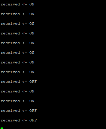
Toggle the button on your Adafruit IO dashboard to change the Lamp state.
So its very easy to integrate Adafruit IO in your IoT project. Also check our other tutorials to control LED and Home Appliances using Raspberry pi from anywhere in the world:
import time
import digitalio
import board
from Adafruit_IO import Client, Feed, RequestError
ADAFRUIT_IO_KEY = 'Your API Key'
# Set to your Adafruit IO username.
# (go to https://accounts.adafruit.com to find your username)
ADAFRUIT_IO_USERNAME = 'Your user name'
aio = Client(ADAFRUIT_IO_USERNAME, ADAFRUIT_IO_KEY)
try: # if we have a 'digital' feed
digital = aio.feeds('digital')
except RequestError: # create a digital feed
feed = Feed(name="digital")
digital = aio.create_feed(feed)
# lamp set up
lamp = digitalio.DigitalInOut(board.D5)
lamp.direction = digitalio.Direction.OUTPUT
while True:
data = aio.receive(digital.key)
if int(data.value) == 1:
print('received <- ON\n')
elif int(data.value) == 0:
print('received <- OFF\n')
# set the lamp to the feed value
led.value = int(data.value)
time.sleep(0.5)


