


There are number of communication technologies available for interaction between IoT devices today, and the most popular ones are Wi-Fi and Bluetooth. But the problem with Wi-Fi and Bluetooth technology is high power consumption. They also have other limitations like limited range, limited access points etc. ESP8266 module is the most popular Wi-Fi module used in IoT devices, using which we have previously built lot of IoT projects.
Cellular networks also have the same problems of high power consumption and both LAN and Cellular network are quite expensive to cover a wide area. The IoT industries introduced lots of technologies, but none of them was ideal for IoT devices, as they needed to transmit information to long distance without using much power, until the LoRa technology was introduced. LoRa Technology can perform very-long range transmission with low power consumption.
In this article, we will learn about LoRa technology and Arduino Lora Communication. Here we will interface SX1278 Lora Module with Arduino and establish LoRa communication between two Arduino Uno boards.
What is LoRa?
LoRa (Long Range) is a wireless technology that offers long-range, low power, and secure data transmission for M2M (Machine to Machine) and IoT applications. LoRa is a spread spectrum modulation technology that is derived from chirp spread spectrum (CSS) technology. LoRa can be used to connect sensors, gateways, machines, devices, etc. wirelessly.
LoRa was introduced by a company called Semtech. LoRa Technologies works in different frequency bands in different countries: In the USA it operates in the 915 MHz band, in Europe region, it operates in the 868 MHz band and in Asia region it operates in the 865 to 867 MHz, 920 to 923 MHz band.
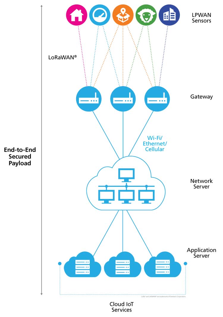
Working of LoRa is more like a cellular communication. LoRa communication block diagram is shown below. The signal from one LoRa Node travels to another Node through a LoRa Gateway. Network server gets signal from LoRa Gateway and sends it to the end-user through Application server.
According to the official information, LoRa can achieve a distance of 715km when there is no obstacle between the Node and Gateway.
Components Required
- 2×Arduino Uno
- 2×LoRa SX1278 Module
- DHT11 Sensor
- LCD 16×2 Module
- Jumper Wires
Circuit Diagram
Circuit diagrams for LoRa transmitting and receiving side are given below. In this project, we are going to send temperature and humidity values from one Arduino to another using LoRa SX1278 module. The DHT11 sensor is connected to transmitting side, Arduino. So this Arduino will get temperature and humidity values from DHT11 and then send it to another Arduino via LoRa SX1278 module. These humidity and temperature values will be printed on LCD connected to second Arduino.
We previously used DHT11 Temperature and Humidity Sensor with Arduino and Raspberry Pi to build Iot based weather stations.
Transmitting Side- Interfacing LoRa with Arduino UNO
On the transmitting side, we will use an Arduino UNO with LoRa module and DHT11 sensor. The interfacing of the Arduino UNO with LoRa and DHT11 is shown below:
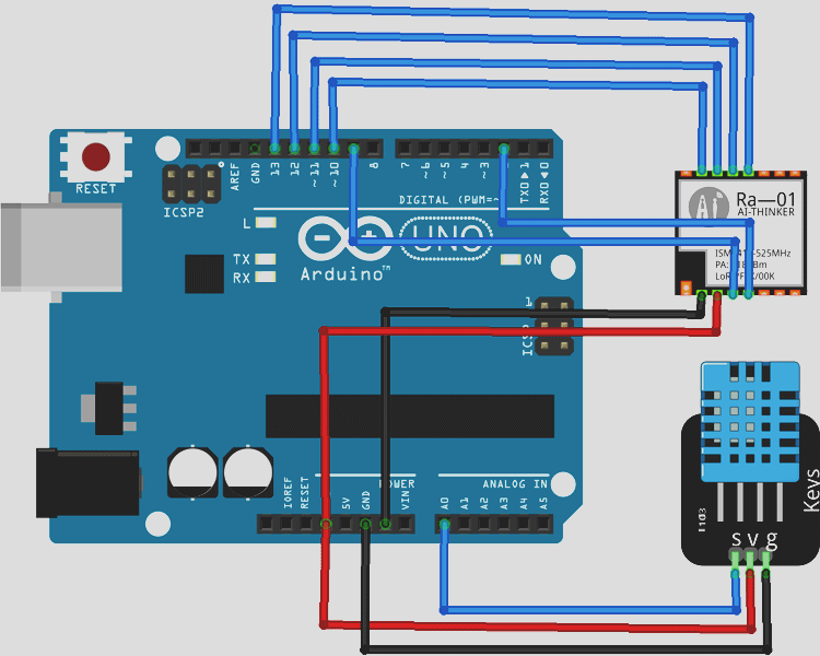
The LoRa module consists of 16 pins, out of these six pins are GPIO pins, and four are Ground pins. This LoRa module operates at 3.3V, and so the 3.3V pin on LoRa is connected to the 3.3v pin on the Arduino UNO board. Complete connections are given in below table. DHT11 sensor is connected to A0 pin of Arduino.
|
LoRa SX1278 Module |
Arduino Uno |
|
3.3V |
3.3V |
|
GND |
GND |
|
NSS |
D10 |
|
DIO0 |
D2 |
|
SCK |
D13 |
|
MISO |
D12 |
|
MOSI |
D11 |
|
RST |
D9 |
|
DHT 11 Sensor |
Arduino Uno |
|
VCC |
3.3V |
|
GND |
GND |
|
DATA |
A0 |
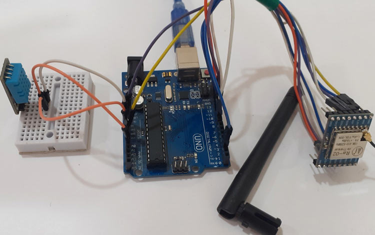
Below is the hardware setup for Arduino Lora Transmitter:
Receiving Side- Interfacing LoRa SX1278 with Arduino UNO
For the Receiving side, we will use an Arduino Uno with LoRa module and 16×2 LCD Display module. The circuit diagram to connect the Arduino with LoRa and LCD module is shown below
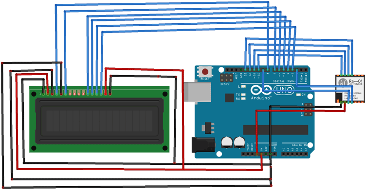
The connections are the same as Trasnsmitter except the LCD module connected with Arduino. Complete connections are given in below table.
|
LoRa SX1278 Module |
Arduino Uno |
|
3.3V |
3.3V |
|
GND |
GND |
|
NSS |
D10 |
|
DIO0 |
D2 |
|
SCK |
D13 |
|
MISO |
D12 |
|
MOSI |
D11 |
|
RST |
D9 |
|
LCD |
Arduino |
|
VSS |
GND |
|
VDD |
5V |
|
VO |
GND |
|
RS |
D8 |
|
RW |
GND |
|
E |
D7 |
|
D4 |
D6 |
|
D5 |
D5 |
|
D6 |
D4 |
|
D7 |
D3 |
|
A |
5V |
|
K |
GND |
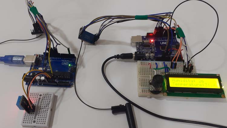
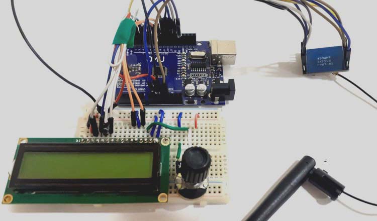
Below is the hardware setup for Arduino Lora Receiver:
Programming Arduino LoRa as Transmitter
Complete program for both Arduinos (Transmitter and Receiver) are given at the end of this tutorial, here we are explaining few important parts of the code.
Start the program by adding the required libraries and initializing the pins. In this code the SPI and LoRa library is used for LoRa module. The DHT11 sensor module is connected to A0 pin of Arduino. You can download the Lora library from here.
#include <SPI.h>
#include <LoRa.h>
#include "DHT.h"
#define DHTPIN A0
Inside the void setup() function we begin the serial monitor. In my case, 433E6 (433 MHz) is my LoRa operating frequency you might have to change it based on the type of module you are using.
void setup() {
  Serial.begin(9600);
  dht.begin();
  while (!Serial);
 if (!LoRa.begin(433E6)) {
    Serial.println("Starting LoRa failed!");
    while (1);
Inside the void loop function, we calculate the temperature and humidity values using DHT.readTemperature() and DHT.readHumidity() functions and begin transmitting the values. On the receiver side, print those values on the 16x2 Display LCD. We have used the keyword “c” to intimate the receiver to print the following information on line 2.
void loop() {
   temp = dht.readTemperature();
   hum = dht.readHumidity();
  LoRa.beginPacket();
  LoRa.print("Humidity: ");
  LoRa.print(hum);
  LoRa.print("c");
  LoRa.pr
Code for LoRa receiver
#include <SPI.h>
#include <LoRa.h>
#include <LiquidCrystal.h>
const int rs = 8, en = 7, d4 = 6, d5 = 5, d6 = 4, d7 = 3; //Mention the pin number for LCD connection
LiquidCrystal lcd(rs, en, d4, d5, d6, d7);//Initialize LCD method
void setup() {
Serial.begin(9600);
lcd.begin(16, 2);
while (!Serial);
Serial.println("LoRa Receiver");
if (!LoRa.begin(433E6)) {
Serial.println("Starting LoRa failed!");
while (1);
}
}
void loop() {
// try to parse packet
int packetSize = LoRa.parsePacket();
if (packetSize) {
// received a paket
Serial.print("Received packet '");
// read packet
while (LoRa.available()) {
char incoming = (char)LoRa.read();
if (incoming == 'c')
{
lcd.setCursor(0, 1);
}
else
{
lcd.print(incoming);
}
}
}
Code for LoRa sender
#include <SPI.h>
#include <LoRa.h>
#include "DHT.h"
#define DHTPIN A0 // what pin we're connected to
#define DHTTYPE DHT11 // DHT 11
DHT dht(DHTPIN, DHTTYPE);
int hum;
float temp; //Stores temperature value
int counter = 0;
void setup() {
Serial.begin(9600);
dht.begin();
while (!Serial);
Serial.println("LoRa Sender");
if (!LoRa.begin(433E6)) {
Serial.println("Starting LoRa failed!");
while (1);
}
}
void loop() {
temp = dht.readTemperature();
hum = dht.readHumidity();
Serial.print("Sending packet: ");
Serial.println(counter);
// send packet
LoRa.beginPacket();
LoRa.print("Humidity: ");
LoRa.print(hum);
LoRa.print("c");
LoRa.print("Temperature:");
LoRa.print(temp);
LoRa.endPacket();
counter++;
delay(5000);
}


