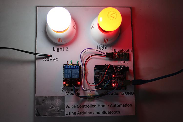
Smart homes have become popular due to their convenience and energy efficiency. An implemented project uses voice commands to wirelessly control home appliances and lights. An Android app performs the speech-to-text conversion and Bluetooth communicates with the microcontroller to execute commands. This eliminates the need for physical interaction with devices. Smart homes can save energy and reduce their carbon footprint by automating tasks and tracking energy usage. Smart technology in homes is an efficient way to make daily tasks easier. Smart home devices can also track energy usage and provide insights for improved efficiency.
Before this, we have built some IoT Home Automation Projects, here are some examples:
- IoT Based Manhole Monitoring System
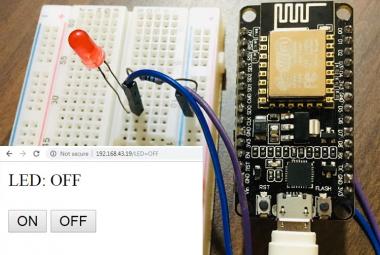
- Create an Android App with Android Studio to control an LED over WiFi using NodeMCU
- Home Automation with Node-RED and Raspberry Pi: Control Lights & Read DHT11 Data
Components Required
- Arduino UNO
- HC-05 Bluetooth Module
- 2-channel Relay Module(5v)
- 2 holders
- 2 Bulb
- 220v Electrical wire with a 2-pin male socket
- Sun board Piece
- Jumper wires
- Nuts & bolts
- And a Smartphone
Bluetooth Module HC-05
It is a widely used module in electronic projects for wireless communication. It uses serial UART communication for data transfer.
The Module can work in two modes:
- Master mode: It can share data with all slaves.
- Slave mode: It receives data from a master Bluetooth.
Here, our Bluetooth module is working as a slave while the smartphone is a master.
HC 05 Pinout
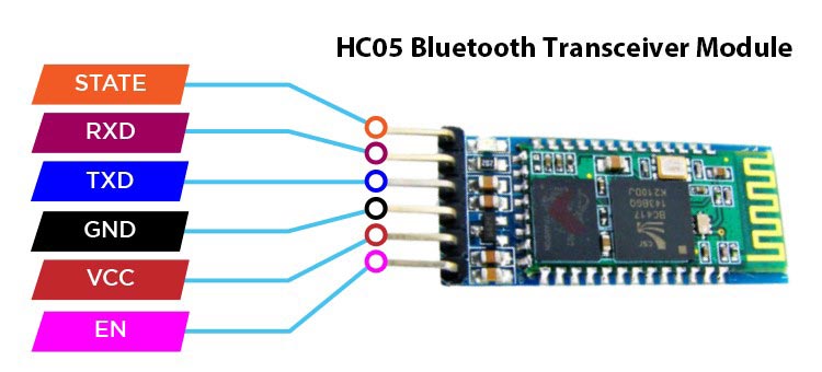
It consists of 6 pins which are STATE, RXD, TXD, GND, VCC, and EN as mentioned on the back of the module.
- STATE pin: This pin defines the state of the module whether it is paired or not with another device.
- RxD pin: This pin uses serial UART communication. This pin is used to send AT command when the module is in command mode.
- TxD pin: This pin uses serial UART communication. This pin is used to push out responses to AT command when the module is in command mode.
- Vcc pin: This pin is used to supply power to the module to make it work. It is typically connected to the 5V pin on the Arduino board. Its voltage range lies between 3.6v to 5v.
- GND pin: This pin is used to connect the module to the ground of the Arduino board.
- EN pin: This pin is used to switch between command and data mode. The module will be in command mode if this pin is set to HIGH. Similarly, the module will be in data mode if this pin is set to LOW.
Relay
It is a switching electro-mechanical device that can be able to switch high Amps of AC- DC power.
Relay Pinout
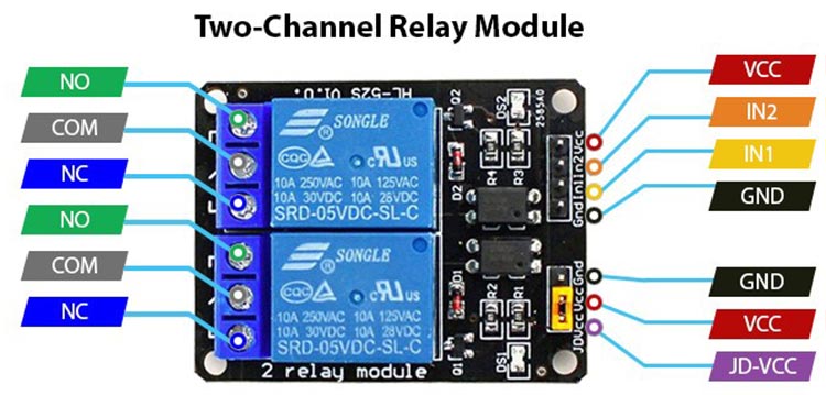
The module has typically four pins:
- Vcc pin: It is used to power up the relay module. It is normally connected to 5v.
- GND pin: It is used to provide ground to the relay module.
- IN1: It is used to control the output of the first relay inside the module.
- IN2: It is used to control the output of the Second relay inside the module.
Also, there are three more pins at the side of the high-voltage terminals of each relay. These are NC (Normally closed), COM(Common), and NO (Normally Open).
Circuit Diagram
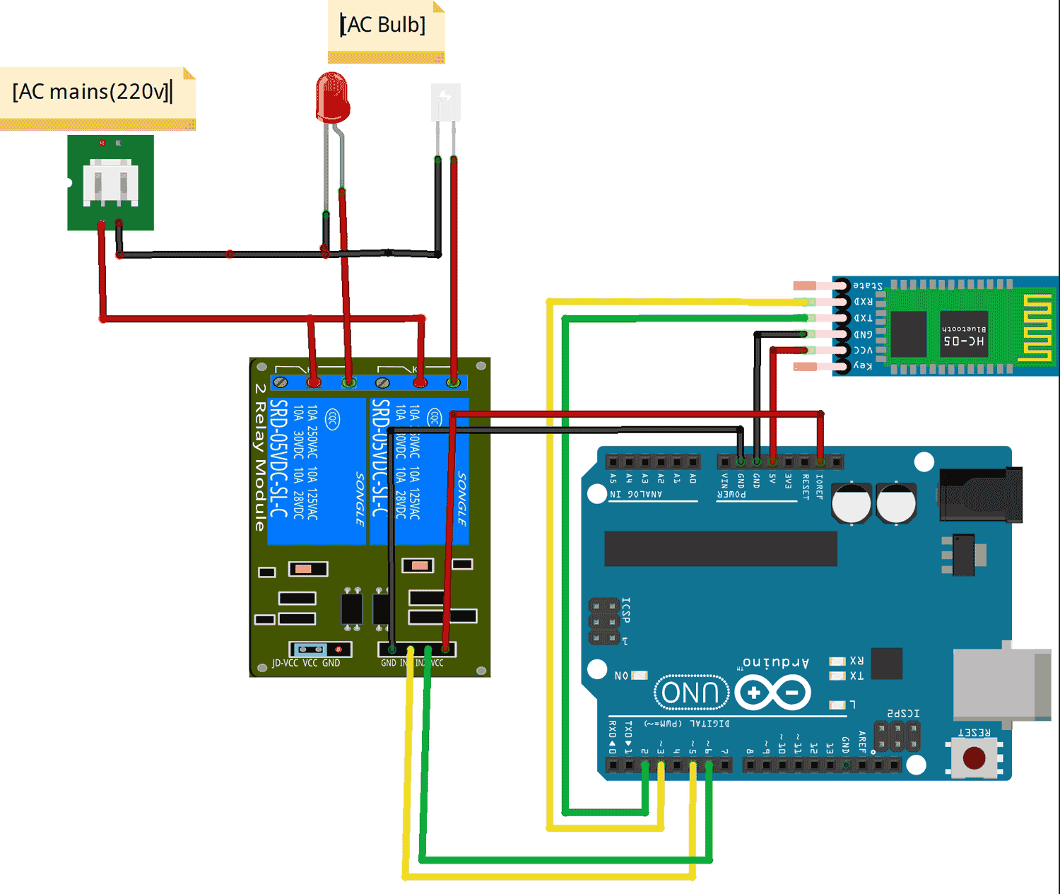
The connections are pretty simple, let's begin.
Bluetooth HC-05: To establish communication between the Arduino and the Bluetooth HC-05 module, pin 3 (Tx defined in code) of the Arduino is connected to the receive pin (RxD) of the Bluetooth module, while pin 2 (Rx) is connected to the transmit pin (TxD). The Bluetooth module is powered by connecting its Vcc and GND pins to the Arduino's respective power and ground pins.
Relay Module: The Arduino pin 5 is connected to IN1 of the relay Module whereas pin 6 is connected to IN2. These input pins are active low, which means that a logic LOW activates the relay and a logic HIGH deactivates it.
The relay module has two LEDs that indicate the status of the relay. When a relay is activated, the corresponding LED lights up. The relay module is powered by connecting its Vcc and GND pins to the Arduino's respective power and ground pins.
On the high-voltage side of the relay module, the COM port of both relays is connected to the live supply of AC. The NO terminal of each relay is connected to each separate bulb, while the Neutral wire is directly connected to both bulbs as shown in the circuit diagram.
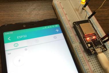
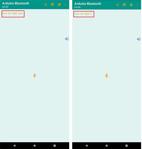
Setting up Voice Command Android App
To use the project first you need to install an app from Playstore called Arduino Bluetooth.
- Download and install the app.
- Give microphone permission and enable Bluetooth.
- Start your project and Pair your device with HC-05.
- Switch to voice mode in the app.
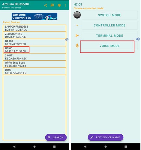
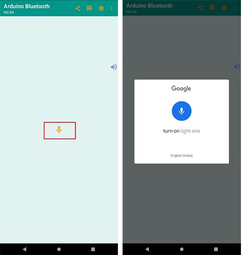
- Tap the microphone icon to begin giving voice commands.
- Speak the correct commands as per your code.
- Enjoy controlling your device with voice prompts.
Arduino Code Explanation
The program reads the Bluetooth module data through serial communication and compares it with defined conditions. If any of the conditions is true, then that task will perform. If any of the condition is not satisfied, it will do nothing.
Firstly, we must include all necessary Libraries for the successful execution of the code. Libraries include SoftwareSerial only. Also, we have defined the necessary variables and objects for further programming.
#include<SoftwareSerial.h>
// Define 2 channel relay pins
const int Light1 = 6; // Relay pin 1 (IN1)
const int Light2 = 5;   // Relay pin 2 (IN2)
/* Create object named bt of the class SoftwareSerial */
SoftwareSerial bt(2, 3); /* (Rx,Tx) */
- We used the Software Serial library to define the Rx & Tx serial communication pins to the Arduino. Other than that, we can directly use Arduino pin (0,1) for Rx and Tx, but it will create a hustle of removing the connection whenever we upload a fresh code.
- Here, we define pin2 as Rx and pin3 as Tx. Always remember that RxD of Bluetooth is connected to Tx of Arduino while TxD is connected to Rx of Arduino.
void setup() {
  bt.begin(9600); /* Define baud rate for software serial communication */
  Serial.begin(9600); /* Define baud rate for serial communication */
  // Set Relay pins as OUTPUT
   pinMode(Light1, OUTPUT);
   pinMode(Light2, OUTPUT);
   digitalWrite(Light1, HIGH);
   digitalWrite(Light2, HIGH);
}
In the setup() function, serial communication is initiated.
- The Bluetooth module can only communicate on the baud rate 9600. Hence, we initialize the BT module.
- Also, we define all Pinmodes.
void loop() {
  String data="";
  char ch;
  while (bt.available()) /* If data is available on serial port */
    { ch = bt.read(); /* Print character received on to the serial monitor */
      data=data+ch;
    }
   Serial.print(data);
  // Control the devices using voice command
    if ((data == "turn on light one")||(data == "turn on light 1"))               // turn on Device1
    {
      digitalWrite(Light1, LOW);
      delay(200);
    }
    else if ((data == "turn off light one")||(data == "turn off light 1"))          // turn off Device1
    {
      digitalWrite(Light1, HIGH);
      delay(200);
    }
    // Control the devices using voice command
    else if ((data == "turn on light two")||(data == "turn on light to")||(data == "turn on light 2")) // turn on Device2
    {
      digitalWrite(Light2, LOW);
      delay(200);
    }
    else if ((data== "turn off light two")||(data == "turn off light to")||(data == "turn off light 2")) // turn off Device2
    {
      digitalWrite(Light2, HIGH);
      delay(200);
    }
}
In the Above loop part, we have done all the processing tasks like reading the serial port, comparing text, and executing the tasks.
- The available data on the serial port is read and stored in the string variable “data”. Further, the stored data is compared with different conditions which we implemented using the IF-Else condition.
- You can change the comparison text according to your ease. Also, you can check the received data on the serial Monitor which was sent by your voice command through your smartphone.
That is all about the code, just upload the code. Be careful about Rx & Tx pins and don’t forget to set the baud rate to 9600 on your serial monitor.
The complete code you will find below in the code section.
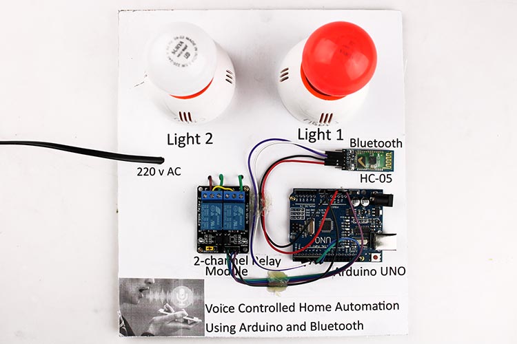
Working of Project
- Power on your project with the uploaded code.
- Open the app and pair your BT module.
- Start sending the voice commands used in your code to control the appliances.
Hope you enjoyed the article and learned something useful from it. If you have any questions, you can leave them in the comment section below.
#include<SoftwareSerial.h>
// DeUfine 2 channel relay pins
const int Light1 = 6; // Relay pin 1 (IN1)
const int Light2 = 5; // Relay pin 2 (IN2)
/* Create object named bt of the class SoftwareSerial */
SoftwareSerial bt(2, 3); /* (Rx,Tx) */
void setup() {
bt.begin(9600); /* Define baud rate for software serial communication */
Serial.begin(9600); /* Define baud rate for serial communication */
// Set Relay pins as OUTPUT
pinMode(Light1, OUTPUT);
pinMode(Light2, OUTPUT);
digitalWrite(Light1, HIGH);
digitalWrite(Light2, HIGH);
}
void loop() {
String data="";
char ch;
while (bt.available()) /* If data is available on serial port */
{ ch = bt.read(); /* Print character received on to the serial monitor */
data=data+ch;
}
Serial.print(data);
// Control the devices using voice command
if ((data == "turn on light one")||(data == "turn on light 1")) // turn on Device1
{
digitalWrite(Light1, LOW);
delay(200);
}
else if ((data == "turn off light one")||(data == "turn off light 1")) // turn off Device1
{
digitalWrite(Light1, HIGH);
delay(200);
}
// Control the devices using voice command
else if ((data == "turn on light two")||(data == "turn on light to")||(data == "turn on light 2")) // turn on Device2
{
digitalWrite(Light2, LOW);
delay(200);
}
else if ((data== "turn off light two")||(data == "turn off light to")||(data == "turn off light 2")) // turn off Device2
{
digitalWrite(Light2, HIGH);
delay(200);
}
}