


The traditional method of taking attendance manually is very time consuming and often times leads to human error. The manual system is also prone to misconduct and the valuable work time gets wasted in organizing and structuring attendance data. This current attendance system can be replaced by a more efficient and effective method by using a smart attendance system using IoT and RFID Technology. RFID is an automated identification and data collection technology. Radiofrequency identification (RFID) is a technology that communicates via electromagnetic waves to exchange data between a terminal and an electronic tag attached to an object, for the purpose of identification and tracking. Some tags can be read from several meters away and beyond the line of sight of the reader
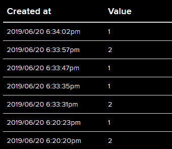
This project is to simplify attendance recording system by using Radio Frequency Identification (RFID) technology. In this project, we are using Arduino Uno, RC522 RFID scanner, and ESP8266 Wi-Fi module. Arduino and RFID scanner scans the RFID cards and then log the data to Adafruit IO cloud platform with the help of ESP8266 Wi-Fi module. This information can be displayed in the Adafruit IO dashboard and can be accessed by the required authorities to view and analyze the attendance over the internet from anywhere at any time.
Components Required
Hardware components
- Arduino Uno
- RFID-RC522
- ESP8266-01
- Jumper Wires
Software apps and online services
- Arduino IDE
- Adafruit IO
Setting up your Adafruit IO account
Adafruit IO is an open data platform that allows you to aggregate, visualize, and analyze live data on the cloud. Using Adafruit IO, you can upload, display, and monitor your data over the internet, and make your project IoT enabled. You can control motors, read sensor data, and make cool IoT applications over the internet using Adafruit IO. For test and try, with some limitation, Adafruit IO is free to use. We have also used Adafruit IO with Raspberry Pi previously.
1. For Adafruit IO setup, the first thing you will need to do is to sign up to Adafruit IO. To sign up go to Adafruit IO’s site https://io.adafruit.com and click on ‘Get started for Free’ on the top right of the screen.

2. After this, a window will pop up where you need to fill your details
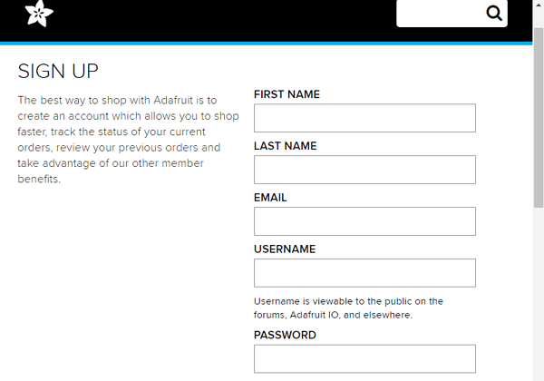
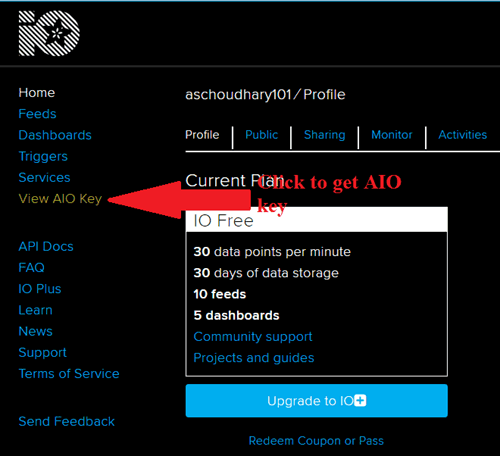
In sign up window fill your details like your name, mail id, username, etc. Then click on save settings, and your account is created. To get your AIO key click on ‘View AIO Key.’
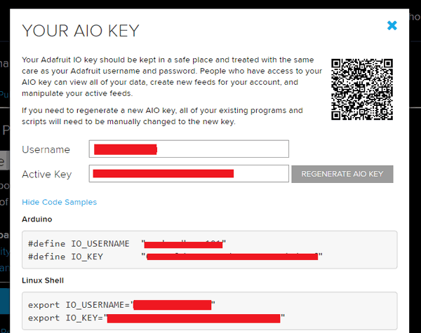
3. A window will pop up with your Adafruit IO AIO Key. Copy this key you'll need it later in your code.
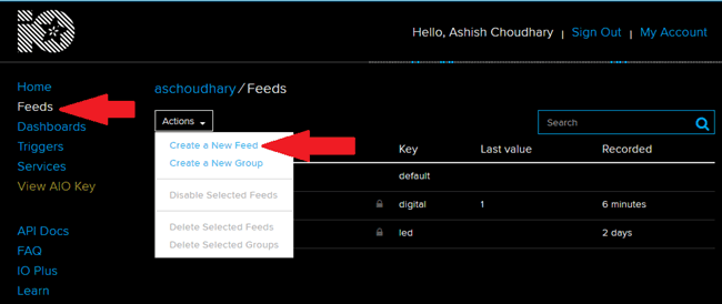
4. Now, after this, you need to create a feed. To create a feed click on ‘Feed.’ Then click on ‘Actions,’ you will see some options from them click on ‘Create a New Feed.’
5. After this a new window will open where you need to input:
Name – In name, option write a short descriptive name of your feed. You can use
Letters, numbers, and spaces.
Description - A long-form description of your data. This field is not required, but you
can write a description of your data.
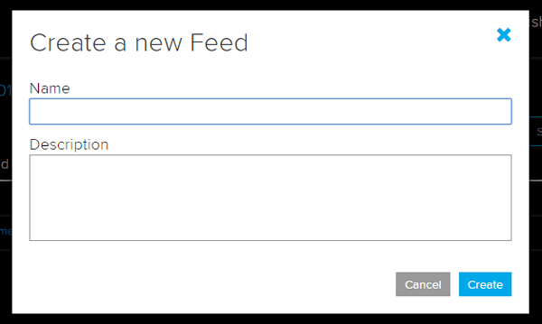
6. Click on ‘Create,’ you will then be redirected to your new feed.
ESP8266-01 Programming
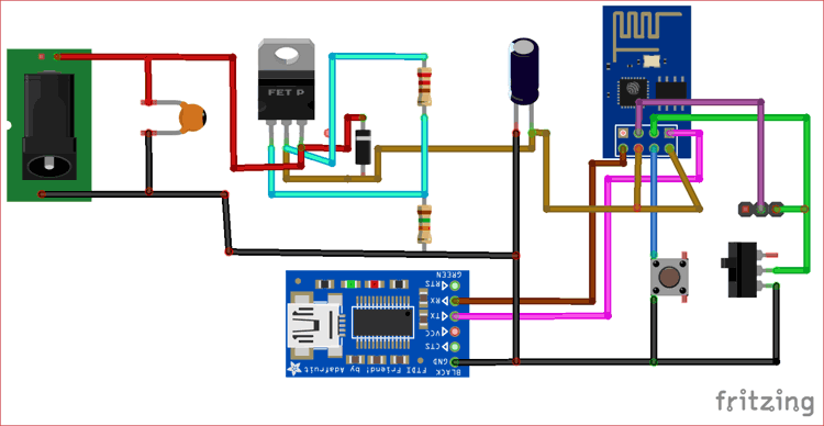
Circuit diagram for programming the ESP8266 using FTDI board is given in below image. Rx, Tx, and GND of the FTDI board are connected with ESP8266. For this project, ESP8266 should be operated both in AT command mode and Programming mode. To change the mode, a toggle switch is used to toggle the ESP8266 between AT command mode, and Programming mode and the push button is used to reset the module.
To put the module in programming mode the GPIO 0 pin of ESP8266 (violet wire) should be connected to ground (green wire) and reset button should be pressed. To put the module in AT command mode the GPIO 0 pin (violet wire) must be left free and reset button should be pressed.
Note that by default the ESP8266-01 module works with AT commands. But when we upload a program to it using Arduino IDE, the default AT command firmware will be override with our Arduino code. To use it with AT command you have to Flash the ESP8266 module with its default firmware.
Programming ESP8266 Using Arduino IDE
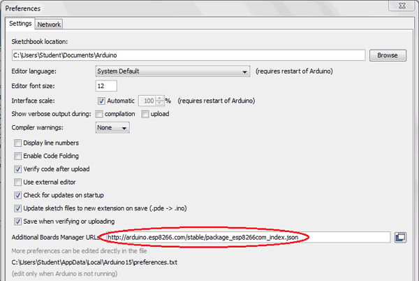
To program ESP8266 with Arduino IDE go to File–>Perferences–>Settings.
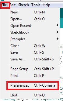
Enter http:// arduino.esp8266.com/stable/package_esp8266com_index.json into ‘Additional Board Manager URL’ field and click ‘Ok.’
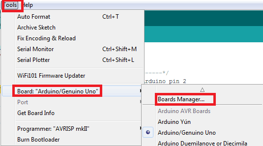
Now go to Tools > Board > Boards Manager.
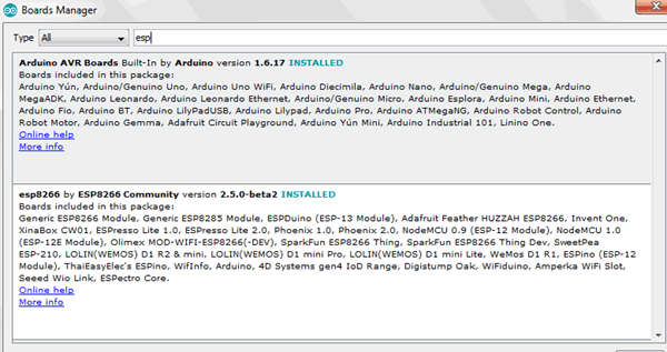
In Boards Manager window, Type esp in the search box, esp8266 will be listed there below. Now select the latest version of the board and click on install.
After installation is complete, go to Tools > Board > Generic ESP8266 Module. Select the correct Port and then upload the code.
Programming ESP8266 for RFID Attendance System
Complete code with a working video is given at the end of this tutorial, here we are explaining the program to understand the working of the project.
Begin the program by adding the required libraries. After this enter the Wifi credential and password with the Adafruit IO username and AIO key that we obtained earlier.
#include <ESP8266WiFi.h>
#include "Adafruit_MQTT.h"
#include "Adafruit_MQTT_Client.h"
#define WLAN_SSID       ""
#define WLAN_PASS       ""
#define AIO_SERVER      "io.adafruit.com"
#define AIO_SERVERPORT  1883
#define AIO_USERNAME    "Username"
#define AIO_KEY         "AIO Key"
Using the setup function, we will begin the serial communication at 11500 baud rate. Then we will connect our Wi-Fi client to the Adafruit IO server.
void setup() {
  Serial.begin(115200);
  Serial.println(F("Adafruit IO Example"));
 Serial.println();
  delay(10);
  Serial.print(F("Connecting to "));
  Serial.println(WLAN_SSID);
 WiFi.begin(WLAN_SSID, WLAN_PASS);
  while (WiFi.status() != WL_CONNECTED) {
    delay(500);
    Serial.print(F("."));
  }
  // connect to adafruit io
  connect();
}
Inside the void loop function, ESP will read the data from the serial and then publish it to the Adafruit IO server.
void loop() {
 // ping adafruit io a few times to make sure we remain connected
  if(! mqtt.ping(3)) {
    // reconnect to adafruit io
    if(! mqtt.connected())
      connect();
  }
  if ( Serial.available() ) { // Update and send only after 1 seconds
   char a = Serial.read();
   ID = a;
   if (! Attendance.publish(ID)) {                     //Publish to Adafruit
      Serial.println(F("Failed"));
    } else {
      Serial.println(F("Sent!"));
    }
   }
}
Once your code is ready, check if the ESP8266 is working or not. Use the FTDI module to upload the code to ESP8266 by keeping it in programming mode. Once the code is uploaded connect it back to AT command mode and press the reset button. Then open serial monitor and you should see that it is connected to Wi-Fi and Adafruit IO.
Circuit Diagram
The complete circuit diagrams for the RFID Smart Attendance system is shown below. The Circuit Diagram was created using Fritzing software.
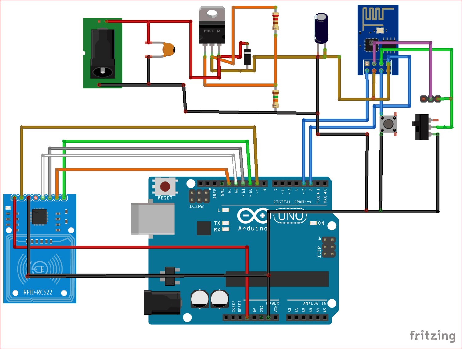
The connection between Arduino and RFID are shown in below table:
|
Pin |
Wiring to Arduino Uno |
|
SDA |
Digital 10 |
|
SCK |
Digital 13 |
|
MOSI |
Digital 11 |
|
MISO |
Digital 12 |
|
IRQ |
Unconnected |
|
GND |
GND |
|
RST |
Digital 9 |
|
3.3V |
3.3V |
Replace the FTDI board with Arduino and RFID-RC522 as shown in above image. The RFID scanner is powered by the 3.3V pin of Arduino and the ESP is powered by LM317 Voltage regulator which regulates 3.3V when powered by a 12V DC adapter. The Arduino UNO module is powered by USB port.
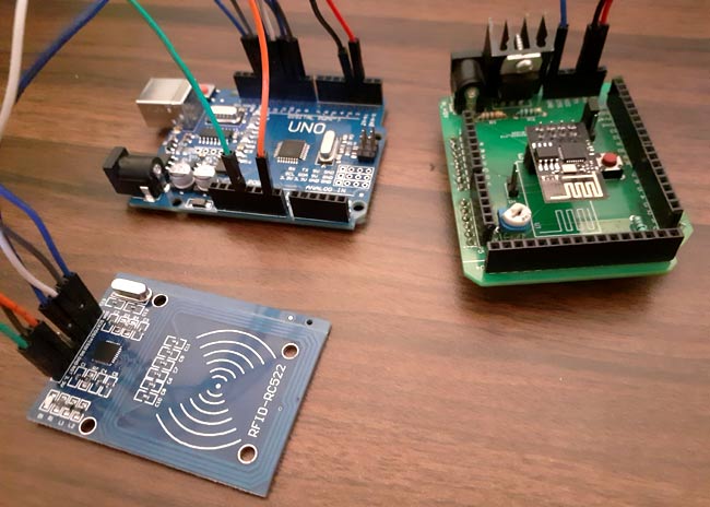
For making the circuit, I have built a PCB for the ESP8266 and LM317 Voltage regulator section by referring to IoT Arduino Wi-Fi Shield by CircuitDigest. But you can also build the complete circuit on a breadboard and things should work fine. My hardware with the connection made looks like this below.
Arduino Uno Program
MFRC522 library is used for the RFID scanner. SDA and RST pins are connected with 10 and 9 pin of Arduino as shown in circuit diagram. You can download the library as zip file from below link and add it to your Arduino IDE.
Download MFRC522 RFID Library for Arduino
#include <SPI.h>
#include <MFRC522.h>
#include "SoftwareSerial.h"
#define SS_PIN 10
#define RST_PIN 9
MFRC522 mfrc522(SS_PIN, RST_PIN);   // Create MFRC522 instance.
SoftwareSerial ser(2,3); // RX, TX
Inside the setup function, we initialize the Serial communication at 9600 and software serial at 115200 baud rate. We have also opened communication with MFRC522.
void setup()
{
  Serial.begin(9600);   // Initiate a serial communication
  ser.begin (115200);
  SPI.begin();      // Initiate  SPI bus
  mfrc522.PCD_Init();   // Initiate MFRC522
  Serial.println("Approximate your card to the reader...");
  Serial.println();
}
Inside the void loop function, we will check if a new card is present, and if a new card is present, then it will check the UID of the card. For a valid card, it will print the UID of the card on the serial monitor; otherwise, it will print ‘unauthorized card.’
void loop()
{
  // Look for new cards
  if ( ! mfrc522.PICC_IsNewCardPresent())
  {
    return;
  }
  // Select one of the cards
  if ( ! mfrc522.PICC_ReadCardSerial())
  {
    return;
  }
  //Show UID on serial monitor

  String content= "";
  byte letter;
  for (byte i = 0; i < mfrc522.uid.size; i++)
  {
     content.concat(String(mfrc522.uid.uidByte[i] < 0x10 ? " 0" : " "));
     content.concat(String(mfrc522.uid.uidByte[i], HEX));
  }
  Serial.println();
  Serial.print("Message : ");
  content.toUpperCase();
  if (content.substring(1) == "60 4E 07 1E" ) //change here the UID of the card/cards that you want to give access
  {
    Serial.println("1");
    ser.write(1);
    Serial.println();

    delay(3000);
Now upload the complete Arduino code given below to the UNO board and connect it with ESP which already has a code running in it. After uploading the code scan the card, for every valid card, it will print the card UID on serial monitor and send the card details to the Adafruit IO.
This is how you can build an IoT based attendance system and connect it to the internet to monitor the attendance over the internet. The complete working of the project can be found at the video linked to the bottom of this page.
Arduino Code:
#include <SPI.h>
#include <MFRC522.h>
#include "SoftwareSerial.h"
#define SS_PIN 10
#define RST_PIN 9
MFRC522 mfrc522(SS_PIN, RST_PIN); // Create MFRC522 instance.
SoftwareSerial ser(2,3); // RX, TX
void setup()
{
Serial.begin(9600); // Initiate a serial communication
ser.begin (115200);
SPI.begin(); // Initiate SPI bus
mfrc522.PCD_Init(); // Initiate MFRC522
Serial.println("Approximate your card to the reader...");
Serial.println();
}
void loop()
{
// Look for new cards
if ( ! mfrc522.PICC_IsNewCardPresent())
{
return;
}
// Select one of the cards
if ( ! mfrc522.PICC_ReadCardSerial())
{
return;
}
//Show UID on serial monitor
String content= "";
byte letter;
for (byte i = 0; i < mfrc522.uid.size; i++)
{
content.concat(String(mfrc522.uid.uidByte[i] < 0x10 ? " 0" : " "));
content.concat(String(mfrc522.uid.uidByte[i], HEX));
}
Serial.println();
Serial.print("Message : ");
content.toUpperCase();
if (content.substring(1) == "60 4E 07 1E" ) //change here the UID of the card/cards that you want to give access
{
Serial.println("1");
ser.write(1);
Serial.println();
delay(3000);
}
if (content.substring(1) == "69 A9 81 5A" ) //change here the UID of the card/cards that you want to give access
{
Serial.println("2");
ser.write(2);
Serial.println();
delay(3000);
}
}
ESP8266 Code:
#include <ESP8266WiFi.h>
#include "Adafruit_MQTT.h"
#include "Adafruit_MQTT_Client.h"
// WiFi parameters
#define WLAN_SSID "Wi-Fi Name"
#define WLAN_PASS "Password"
// Adafruit IO
#define AIO_SERVER "io.adafruit.com"
#define AIO_SERVERPORT 1883
#define AIO_USERNAME "Username"
#define AIO_KEY "AIO Key" // Obtained from account info on io.adafruit.com
// Create an ESP8266 WiFiClient class to connect to the MQTT server.
WiFiClient client;
// Setup the MQTT client class by passing in the WiFi client and MQTT server and login details.
Adafruit_MQTT_Client mqtt(&client, AIO_SERVER, AIO_SERVERPORT, AIO_USERNAME, AIO_KEY);
Adafruit_MQTT_Publish Attendance = Adafruit_MQTT_Publish(&mqtt, AIO_USERNAME "/feeds/feed name");
char ID;
/*************************** Sketch Code ************************************/
void setup() {
Serial.begin(115200);
Serial.println(F("Adafruit IO Example"));
// Connect to WiFi access point.
Serial.println(); Serial.println();
delay(10);
Serial.print(F("Connecting to "));
Serial.println(WLAN_SSID);
WiFi.begin(WLAN_SSID, WLAN_PASS);
while (WiFi.status() != WL_CONNECTED) {
delay(500);
Serial.print(F("."));
}
Serial.println();
Serial.println(F("WiFi connected"));
Serial.println(F("IP address: "));
Serial.println(WiFi.localIP());
// connect to adafruit io
connect();
}
// connect to adafruit io via MQTT
void connect() {
Serial.print(F("Connecting to Adafruit IO... "));
int8_t ret;
while ((ret = mqtt.connect()) != 0) {
switch (ret) {
case 1: Serial.println(F("Wrong protocol")); break;
case 2: Serial.println(F("ID rejected")); break;
case 3: Serial.println(F("Server unavail")); break;
case 4: Serial.println(F("Bad user/pass")); break;
case 5: Serial.println(F("Not authed")); break;
case 6: Serial.println(F("Failed to subscribe")); break;
default: Serial.println(F("Connection failed")); break;
}
if(ret >= 0)
mqtt.disconnect();
Serial.println(F("Retrying connection..."));
delay(5000);
}
Serial.println(F("Adafruit IO Connected!"));
}
void loop() {
// ping adafruit io a few times to make sure we remain connected
if(! mqtt.ping(3)) {
// reconnect to adafruit io
if(! mqtt.connected())
connect();
}
if ( Serial.available() ) { // Update and send only after 1 seconds
char a = Serial.read();
ID = a;
if (! Attendance.publish(ID)) { //Publish to Adafruit
Serial.println(F("Failed"));
} else {
Serial.println(F("Sent!"));
}
}
}


