


After the COVID-19 outbreak, the contactless temperature measurement devices are getting very popular and most of them use the infrared temperature sensor. This device measures the temperature of the person without any physical contact. Today we will also use NodeMCU and Arduino IDE to interface MLX90614 infrared temperature sensor.
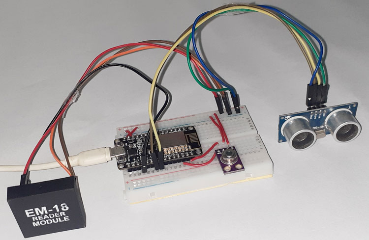
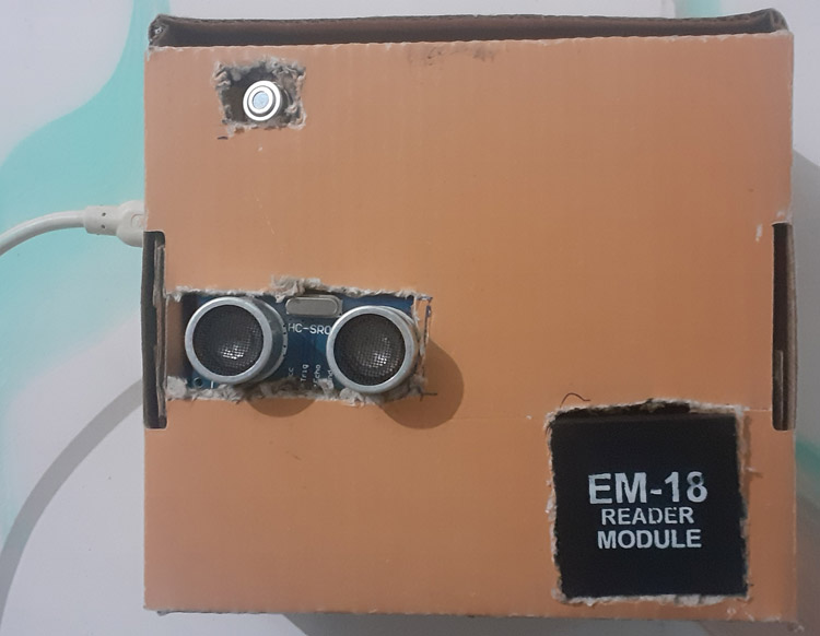
So in this tutorial, we are going to build an IoT Based Smart Employee Temperature Screening system using NodeMCU, MLX90614 Infrared Thermometer, EM18 RFID Reader, and Ultrasonic Sensor. It can measure employee’s body temperature with a non-contact infrared temperature sensor and send the Name and Temperature of that employee to a webpage that can be monitored from anywhere using the internet. The webpage stores the time, Name of the person, and temperature in a table. The Ultrasonic Sensor is used to measure the distance between the sensor and person so that the MLX90614 sensor can measure the temperature when the distance between the sensor and person is less than 20cm for better accuracy.
Components Required
- NodeMCU ESP8266
- EM18 RFID Module
- MLX90614 Infrared Thermometer
- Ultrasonic Sensor
- Breadboard
- Jumper Wires
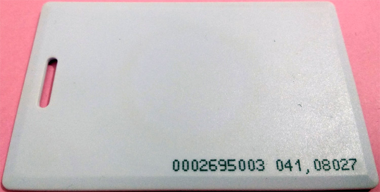
EM18 RFID Reader Module
The EM18 RFID Reader Module is a low cost, low power consumption, small size & easy to use device ideal to develop an RFID system. This module is used for reading 125 kHz tags and directly connects to any microcontroller or PC through UART and an RS232 converter. It can provide output through UART/Wiegand26.
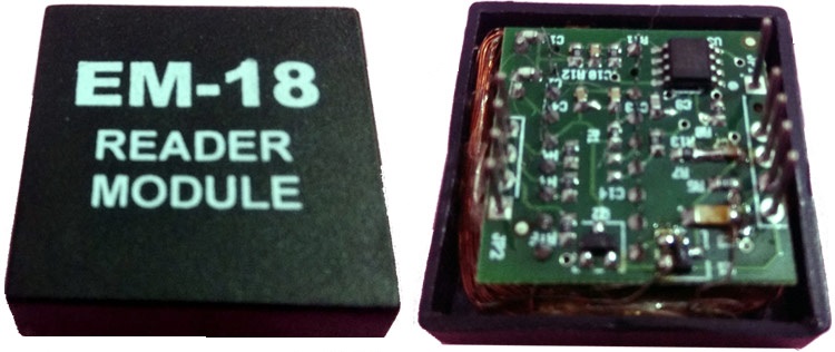
The Reader module comes with an on-chip antenna and can be powered up with a 5V power supply. When you scan the RFID card on the reader module, the transponder inside the card transfers all the information, such as a specific ID in the form of an RF signal to the RFID Module. This reader module also has a BUZ pin that can be used to connect a Buzzer to detect a valid RFID card.
We previously used the same EM18 RFID module for building Smart Shopping Cart.
MLX90614 Infrared Temperature Sensor
Here we have interfaced with a Contactless Temperature Sensor with NodeMCU, named MLX90614. It is an infrared thermometer designed for non-contact temperature sensing. It comes factory calibrated with a digital SM Bus output which gives complete access to the temperature measured in the maximum temperature range with a resolution of 0.02°C and it can be used to measure the temperature of a particular object ranging from -70° C to 382.2°C with an accuracy of about 0.5C at room temperature.
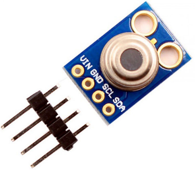
It has two devices embedded in it, one is the infrared thermopile detector (sensing unit) and the other is a signal conditioning application processor. It works based on Stefan-Boltzmann law which states that any object that isn't below absolute zero (0°K) emits light in the infrared spectrum that is directly proportional to its temperature. The sensing unit of the sensor uses the emitted light to measure the temperature of the object.
Circuit Diagram
Circuit Diagram for Infrared Thermometer using ESP8266 NodeMCU is given below:
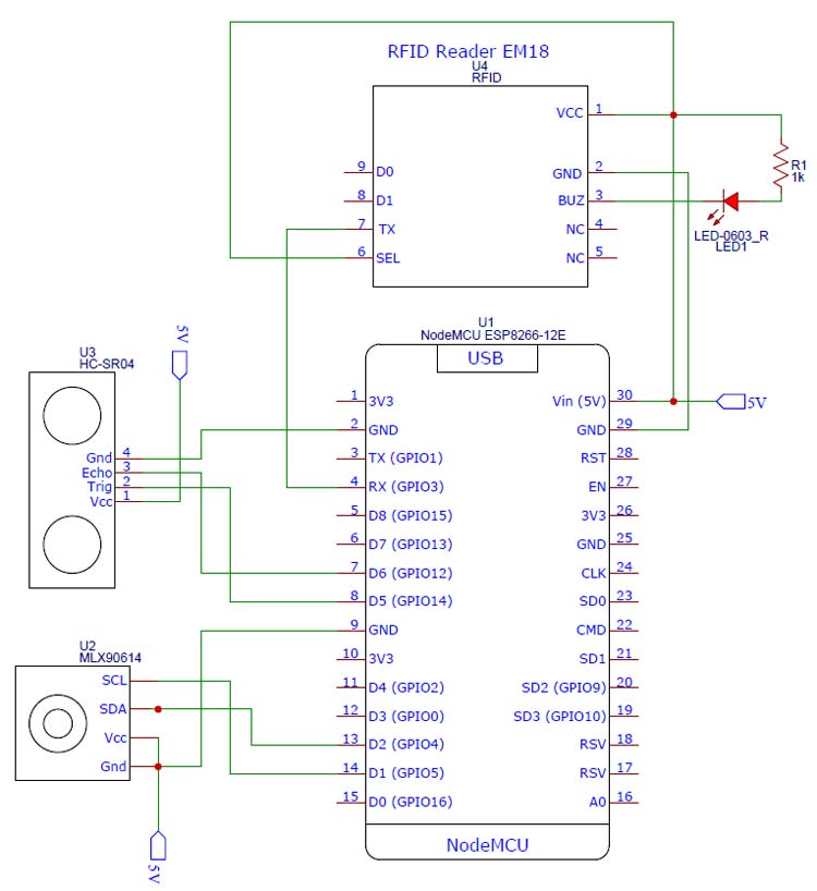
As shown in the circuit diagram, the connections are very simple since we have used them as modules, we can directly build them on a breadboard. The LED connected to the BUZ pin of the EM18 Reader module turns high when someone scans the tag. The RFID module sends data to the controller in serial; hence the transmitter pin of the RFID module is connected to the Receiver pin of NodeMCU. The connections are further classified in the table below:
|
NodeMCU |
EM18 RFID Module |
|
Vin |
Vcc |
|
GND |
GND |
|
Vin |
SEL |
|
Rx |
Tx |
|
NodeMCU |
MLX90614 |
|
Vin |
Vcc |
|
GND |
GND |
|
D1 |
SCL |
|
D2 |
SDA |
|
NodeMCU |
Ultrasonic Sensor (HCSR-04) |
|
Vin |
Vcc |
|
GND |
GND |
|
D5 |
Trig |
|
D6 |
Echo |
Programming NodeMCU
Complete code for this infrared temperature screening project can be found at the end of the page. Here the same program will be explained in small snippets.
NodeMCU Code
This part of the code will read the Ultrasonic sensor, MLX90614, and RFID module and send this data to the webserver. Before programming the NodeMCU, install the required libraries from the given links:
Start the code by including all the required libraries. Here the Wire library is used to communicate using I2C protocol and the Adafruit_MLX90614.h library which is used to read the MLX90614 sensor data.
#include <Wire.h>
#include <Adafruit_MLX90614.h>
#include <ESP8266WiFi.h>
#include <WiFiClient.h>
#include <ESP8266WebServer.h>
After that, enter your Wi-Fi name and Password.
const char* ssid = "Wi-Fi Name";
const char* pass = "Password";
Then in the next lines, we defined the pins where the ultrasonic sensor is connected. We have connected the trig pin to D5 and Echo pin to D6
const int trigPin = 5;
const int echoPin = 6;
After that, define the variables to store the RFID module, ultrasonic sensor, and MLX90614 sensor data and card ID.
char tag[] ="180088FECCA2";
char input[12];
long duration;
int distance;
String RfidReading;
float TempReading;
The handleRoot() function is executed when we open the Webpage in our browser using the NodeMCU IP address.
void handleRoot()
{
 String s = MAIN_page;
server.send(200, "text/html", s);
}
Inside the void setup() function, initialize the baud rate and MLX90614 sensor using begin() function and also initialize Webpage using the server.begin() function. Then connect the module with the Wi-Fi using the Wi-Fi name and password. Also, set the Trig and Echo pins as output and input pins.
Serial.begin(9600);
pinMode(trigPin, OUTPUT);
pinMode(echoPin, INPUT);
mlx.begin();
WiFi.begin(ssid, pass);
server.on("/", handleRoot);
server.begin();
To learn more about the ultrasonic sensor and its Trig and Echo pin, follow our previous Ultrasonic sensor based projects.
Inside the void loop() function, calculate the distance between the person and the sensor and if the distance is less than or equal to 20cm, then call the reader() function to scan the tag.
void loop()
{
digitalWrite(trigPin, LOW);
delayMicroseconds(2);
digitalWrite(trigPin, HIGH);
delayMicroseconds(10);
digitalWrite(trigPin, LOW);
duration = pulseIn(echoPin, HIGH);
distance = duration * 0.0340 / 2;
if (distance <= 20){
reader();
}
The void reader() function will be called when the distance is less than 20 CM, inside this function, we compare the scanned card data with the predefined tag ID. If the tag ID matches the scanned card, then read the temperature of the person and send the temperature and name of the person to WebServer.
if(flag == 1)
{
temp_read();
String data = "{\"Name\":\""+ String(RfidReading) +"\", \"Temperature\":\""+ String(TempReading) +"\"}";
server.send(200, "text/plane", data);
}
Inside the temp_read() function, read the MLX90614 sensor data in Celsius and store it in the ‘TempReading’ variable.
voidtemp_read()
{
 TempReading = mlx.readObjectTempC();
 Serial.println(TempReading);
}
HTML Code for Webpage
The <!DOCTYPE html > tag is used to tell the web browser that which version of html we are using to write the html code.
<!doctype html>
The code written between the <html></html> tags will be read by the browser. The <head></head> tag is used to define the title, header line, and style of the web page. The data written in the <title></title> is the name of the tab in the browser. The <style></style> tag is used to style the table and the header lines.
<html>
<head>
<title>Data Logger</title>
<h1 style="text-align:center; color:red;">Iot Design Pro</h1>
<style>
canvas
{
 -moz-user-select: none;
 ……………………..
 ……………………..
 ……………………..
 </style>
 </head>
The <script></script> tag is used to include the jQuery. The jQuery is the JavaScript library. The getData() function inside the <script> tag is used to get the data from NodeMCU and update the data table.
functiongetData()
{
…………..
…………..
The XMLHttpRequestobject is used to request data from the webserver. All browsers have a built-in XMLHttpRequest object to request data from a server. Using the XMLHttpRequest, we can update a web page without reloading the page, request data from the server, receive data from a server, and can send data to a server. Here we are using this object to get the temperature and Name of the person from the NodeMCU and update the data table without refreshing the web page.
varxhttp = new XMLHttpRequest();
xhttp.onreadystatechange = function()
{
if (this.readyState == 4 &&this.status == 200)
{
var time = new Date().toLocaleTimeString();
var txt = this.responseText;
varobj = JSON.parse(txt);
Nvalues.push(obj.Name);
Tvalues.push(obj.Temperature);
timeStamp.push(time);
timeStamp.push(time);
The open() and send() methods of the XMLHttpRequest object are used to send a request to a server. The syntax for xhttp.open() is given below:
xhttp.open(method, URL, async)
Where:
method is the type ofrequest (GET or POST)
URL is the server location
async is used to define asynchronous or synchronous, where true is asynchronous and false is synchronous
xhttp.open("GET", "readData", true);
xhttp.send();
Testing the Infrared Thermometer
Once the hardware and the program are ready, upload the program into your NodeMCU. Now open serial monitor with 9600 baud rate and get the IP address of NodeMCU. The ultrasonic sensor continuously calculates the distance. When the calculated distance between you and sensor is less than 20 cm, scan your card and if your card is authorized, the MLX sensor will read your temperature. To check the data on the webpage, enter your IP address in the web browser, and your Webpage will look like this:
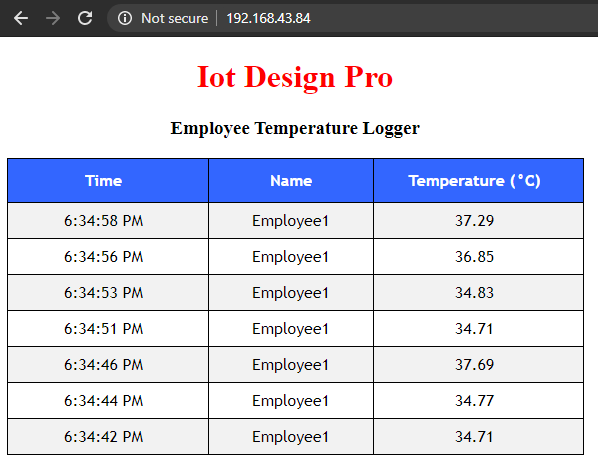
This is how a temperature-based attendance system can be built easily which can not only authorize the employee based on the RFID card but can also log the temperature of the person.
#include <ESP8266WiFi.h>
#include <WiFiClient.h>
#include <ESP8266WebServer.h>
#include <Wire.h>
#include <Adafruit_MLX90614.h>
const char *ssid = "Galaxy-M20"; // Enter your WiFi Name
const char *pass = "ac312124"; // Enter your WiFi Password
ESP8266WebServer server(80); //Server on port 80
Adafruit_MLX90614 mlx = Adafruit_MLX90614();
char tag[] ="180088FECCA2"; // Replace with your own Tag ID
char input[12]; // A variable to store the Tag ID being presented
int count = 0; // A counter variable to navigate through the input[] character array
boolean flag = 0; // A variable to store the Tag match status
const int trigPin = D5;
const int echoPin = D6;
long duration;
int distance;
String RfidReading;
float TempReading;
const char MAIN_page[] PROGMEM = R"=====(
<!doctype html>
<html>
<head>
<title>Data Logger</title>
<h1 style="text-align:center; color:red;">Iot Design Pro</h1>
<h3 style="text-align:center;">Employee Temperature Logger</h3>
<style>
canvas{
-moz-user-select: none;
-webkit-user-select: none;
-ms-user-select: none;
}
/* Data Table Styling*/
#dataTable {
font-family: "Trebuchet MS", Arial, Helvetica, sans-serif;
border-collapse: collapse;
width: 100%;
text-align: center;
}
#dataTable td, #dataTable th {
border: 1px solid #000000;
padding: 8px;
}
#dataTable tr:nth-child(even){background-color: #f2f2f2;}
#dataTable tr:hover {background-color: #ddd;}
#dataTable th {
padding-top: 12px;
padding-bottom: 12px;
text-align: center;
background-color: #3366ff;
color: white;
}
</style>
</head>
<body>
<div>
<table id="dataTable">
<tr><th>Time</th><th>Name </th><th>Temperature (°C)</th></tr>
</table>
</div>
<br>
<br>
<script>
var Tvalues = [];
var Nvalues = [];
var timeStamp = [];
setInterval(function() {
// Call a function repetatively with 5 Second interval
getData();
}, 1000); //5000mSeconds update rate
function getData() {
var xhttp = new XMLHttpRequest();
xhttp.onreadystatechange = function() {
if (this.readyState == 4 && this.status == 200) {
//Push the data in array
var time = new Date().toLocaleTimeString();
var txt = this.responseText;
var obj = JSON.parse(txt);
Nvalues.push(obj.Name);
Tvalues.push(obj.Temperature);
timeStamp.push(time);
//Update Data Table
var table = document.getElementById("dataTable");
var row = table.insertRow(1); //Add after headings
var cell1 = row.insertCell(0);
var cell2 = row.insertCell(1);
var cell3 = row.insertCell(2);
cell1.innerHTML = time;
cell2.innerHTML = obj.Name;
cell3.innerHTML = obj.Temperature;
}
};
xhttp.open("GET", "reader", true); //Handle readData server on ESP8266
xhttp.send();
}
</script>
</body>
</html>
)=====";
void handleRoot() {
String s = MAIN_page; //Read HTML contents
server.send(200, "text/html", s); //Send web page
}
void setup()
{
Serial.begin(9600); // Initialise Serial Communication with the Serial Monitor
pinMode(trigPin, OUTPUT);
pinMode(echoPin, INPUT);
mlx.begin();
WiFi.begin(ssid, pass); //Connect to your WiFi router
Serial.println("");
// Wait for connection
while (WiFi.status() != WL_CONNECTED) {
delay(500);
Serial.print(".");
}
//If connection successful show IP address in serial monitor
Serial.println("");
Serial.print("Connected to ");
Serial.println(ssid);
Serial.print("IP address: ");
Serial.println(WiFi.localIP()); //IP address assigned to your ESP
server.on("/", handleRoot); //Which routine to handle at root location. This is display page
server.on("/reader", reader); //This page is called by java Script AJAX
server.begin(); //Start server
Serial.println("HTTP server started");
}
void loop()
{
server.handleClient();
digitalWrite(trigPin, LOW);
delayMicroseconds(2);
digitalWrite(trigPin, HIGH);
delayMicroseconds(10);
digitalWrite(trigPin, LOW);
duration = pulseIn(echoPin, HIGH);
distance = duration * 0.0340 / 2;
// Serial.println("Distance");
//Serial.println(distance);
if (distance <= 20){
reader();
}
delay(1000);
}
void reader()
{
if(Serial.available())// Check if there is incoming data in the RFID Reader Serial Buffer.
{
count = 0; // Reset the counter to zero
while(Serial.available() && count < 12)
{
input[count] = Serial.read(); // Read 1 Byte of data and store it in the input[] variable
count++; // increment counter
delay(5);
}
if(count == 12) //
{
count =0; // reset counter varibale to 0
flag = 1;
while(count<12 && flag !=0)
{
if(input[count]==tag[count])
flag = 1; // everytime the values match, we set the flag variable to 1
else
flag= 0;
count++; // increment i
RfidReading = "Employee1";
}
}
if(flag == 1) // If flag variable is 1, then it means the tags match
{
//Serial.println("Access Allowed!");
Serial.println(RfidReading);
temp_read();
String data = "{\"Name\":\""+ String(RfidReading) +"\", \"Temperature\":\""+ String(TempReading) +"\"}";
server.send(200, "text/plane", data);
}
else
{
// Serial.println("Access Denied"); // Incorrect Tag Message
}
for(count=0; count<12; count++)
{
input[count]= 'F';
}
count = 0; // Reset counter variable
}
}
void temp_read()
{
TempReading = mlx.readObjectTempC();
Serial.println(TempReading);
// Serial.print(",");
//Serial.print("Ambient ");
//Serial.print(mlx.readAmbientTempC());
//Serial.print(" C");
// Serial.print("Target ");
// Serial.print(mlx.readObjectTempC());
// Serial.print(" C");
// delay(1000);
}


