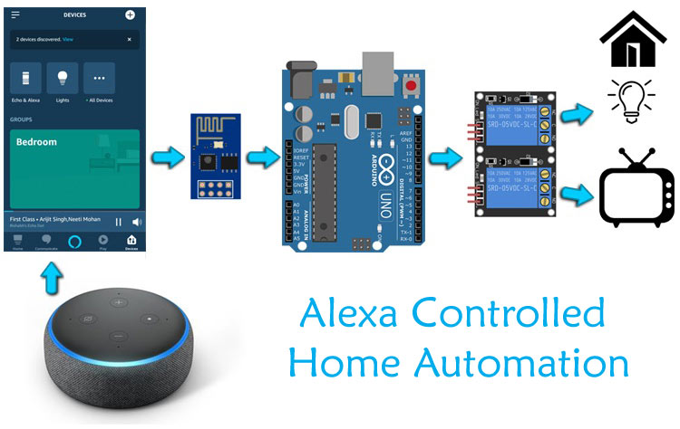
In previous tutorial, we built an Alexa controlled Home Automation system using NodeMCU. It was easy to build and implement. But sometimes we need more number of pins to control more appliances, in that case we can use some microcontroller having more GPIO pins with ESP8266 board. Here we will be using Arduino Uno and ESP8266 to build an IoT based Home automation System.
So in this tutorial we will learn how to control home appliances using Amazon Echo Dot Speaker with voice command. It is not that we are super lazy to toggle loads with switches, but in the age of IoT where everything is becoming “Smart”, we should also build a Smart Home Automation System. IoT based Home automation is very popular nowadays and we have previously done many IoT Home Automation Projects using different controllers like Raspberry Pi, ESP8266, Arduino etc.
Materials Required
1. Arduino Uno
2. Amazon Alexa dot speaker
3. ESP8266-01
4. Jumper Wires
5. Breadboard or Zero PCB
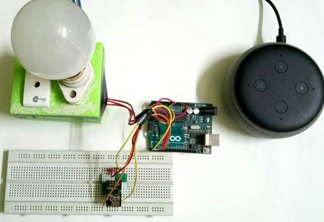
As already explained in previous tutorial that there are various ways to control home appliances using Alexa and the most popular method is by using Third party services like ThingSpeak, IFTTT and Webhooks. But these methods require configuration on every platform and this makes the task little cumbersome and time taking. Also, coding part need some calculations for getting characters and decoding them. For invoking Alexa in this method need some extra phrase like to turn on the bulb, we have to say that “Alexa, Alexa trigger turn on the bulb”. As you can see we have to say “Alexa trigger” on every invocation, this sounds very odd. So because of this much complexity we will use our previous method i.e. by using fauxmoESP library.
FauxmoESP library is available only for ESP boards and it doesn’t support Arduino boards. Now, how to implement it in Arduino? Don’t worry we have a method to implement this. Here we will not use the ESP8266 module in AT mode but will use it in programming mode. So, we will upload the fauxmoESP code in this module and send a different character using serial communication whenever there is a change in state received (0 or 1) from Alexa. These characters will be received on Arduino board just like it receives data from Bluetooth module when it is interfaced with Arduino.
Installing Libraries for IoT Alexa Home automation
As we will create multiple virtual connections environment on ESP so we need to install fauxmoESP along with Asynchronous TCP library.
1. For ESP8266 download the Asynchronous TCP library from this link and for ESP32 download it from this link.
2. Then download fauxmoESP library from this link .
3. Now, unzip these files in libraries folder in your Arduino directory which can be found in Documents folder. Also, rename these folders as oseperez-fauxmoesp-50cbcf3087f to xoseperez_fauxmoesp and ESPAsyncTCP-master to ESPAsyncTCP.
4. There is an example code in fauxmoESP for controlling appliances we have to modify this example. Open Arduino IDE and go to Examples -> FauxmoESp -> fauxmoESP_Basic.
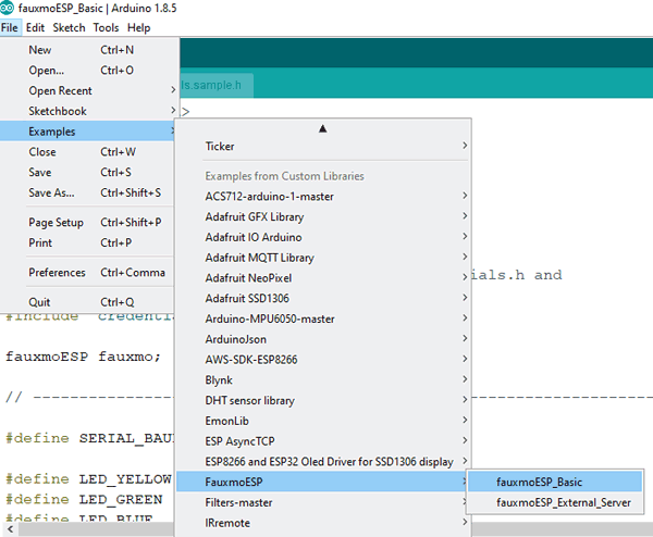
Before starting with the coding part, make sure you have installed ESP board files. If you don’t have board files then follow our previous tutorials on getting started with ESP using Arduino IDE.
Code and Working Explanation
Complete code with a working video for this Arduino based Alexa controlled Home appliances is given at the end of this tutorial, here we are explaining the code for ESP8266 and Arduino separately to understand the working of the project.
ESP8266 Programming Part
This part will remain same as we have done in previous tutorial. But here are some modifications because here the data will be sent to Arduino using serial communication.
First, we include important header files for ESP board and fauxmoESP.
#include <Arduino.h>
#include <ESP8266WiFi.h>
#include "fauxmoESP.h"
Then Define baud rate of 115200 and Wi-Fi-SSID and Password. Also, make an instance for fauxmoESP as fauxmo so that we can use this in our code.
#define SERIAL_BAUDRATE 115200
#define WIFI_SSID "*******"
#define WIFI_PASS "*******"
fauxmoESP fauxmo;
Make a separate function for Wi-Fi setup so that it can be called in void setup function. Make the WiFi mode as station mode and pass the SSID and Password in WiFi.begin() function. Wait for the connection to establish. Also, note that do not use Serial.print or println() unnecessarily because it will send this data to Arduino. So, avoid using it.
void wifiSetup() {
  WiFi.mode(WIFI_STA);
  WiFi.begin(WIFI_SSID, WIFI_PASS);
  while (WiFi.status() != WL_CONNECTED) {
..
..
}
In void setup() function, pass the baud rate to serial.begin function and call the wifisetup function.
void setup() {
  Serial.begin(SERIAL_BAUDRATE);
  wifiSetup();
Now, fauxmoESP has to create its own webserver, for this we pass true in createserver function and set port number as 80. If you make false in enable function then it will prevent the devices from being discovered and switched.
  fauxmo.createServer(true);
  fauxmo.setPort(80);
fauxmo.enable(true);
Add devices using fauxmo.addDevice() function. The argument will be the name of your device that you will use to ask Alexa to switch it on/off.
  fauxmo.addDevice(bedroom_light);
  fauxmo.addDevice(tv);
Now, make a function to handle the command received from Alexa. In this function we will compare the string with the device name and if it is matched then send a character to Arduino using Serial.print or Serial.write.
  fauxmo.onSetState([](unsigned char device_id, const char * device_name, bool state, unsigned char value) {
    if ( (strcmp(device_name, bedroom_light) == 0) ) {
      if (state) {
Serial.print("a");
      } else {
        Serial.print("b");
      }
    }
Similarly, do the same for second device but send different character to Arduino this time.
In void loop() function, just check for the incoming packets from Alexa server using fauxmo.handle function and it will take the actions using onSetstate() function .
void loop() {
  fauxmo.handle();
..
}
Complete code for ESP8266 is given at the end of the tutorial. Use FTDI module or Arduino Uno board to program ESP8266-01. We will use Arduino board to program it. Upload a blank sketch or BareMinimum example code in Arduino board and make the connection as shown in the circuit diagram below. Learn more about programming ESP8266 using FTDI module here.
Arduino Programming Part
Arduino code for Alexa Home Automation is very simple. You have to just check for the incoming data using Serial.available() function, when this data match with the condition given in if statements then trigger the relay.
void loop() {
   if(Serial.available() > 0)
  {
    data = Serial.read();
    Serial.print(data);
    Serial.print("\n");
    if(data == 'a')
      digitalWrite(5, HIGH);
    else if(data == 'b')
      digitalWrite(5, LOW);
  }
Similarly, for other relay.
}
Circuit diagram
First, to program the ESP8266 using Arduino board, make the following connections and choose Board as Generic ESP8266 and select correct port number. Finally, Hit the upload button.
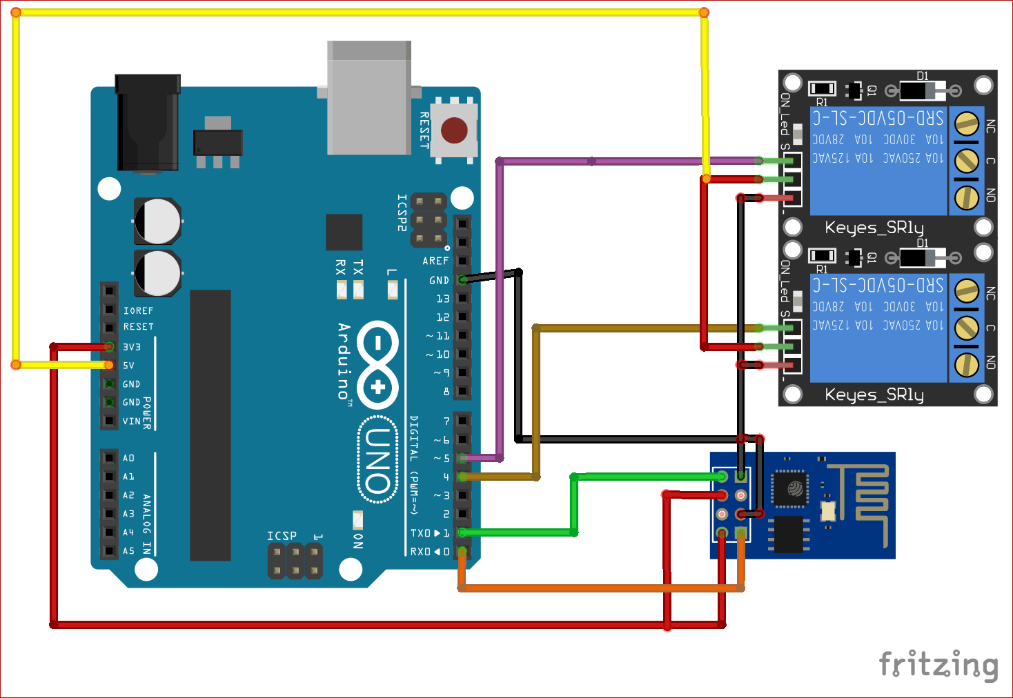
After programming the module, just remove Rx Tx wires from Arduino and upload the Arduino part code.
Then make the connection again but with slight changes.
Connect Rx of ESP8266 -> Tx of Arduino
Connect Tx of ESP8266 -> Rx of Arduino
Remove GPIO 0 of Esp8266 from the GND.
All connections remains same except above changes.
Now, we are done with the coding and hardware part. Its time to test our Home automation system. Also, note that the Wi-Fi network should remain same for both the ESP8266 and Amazon echo dot i.e. they have to share same Wi-Fi.
Testing the Arduino based Alexa Home Automation System
Now, try saying Alexa, Discover Devices. Alexa will respond like Starting discovering… I found two devices, try saying “Alexa, turn on Bedroom light”.
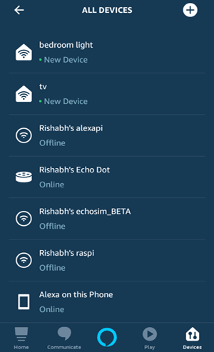
Alternatively, you can discover these devices in your Alexa app. Tap on + sign and then discover devices. You should see two devices namely Bedroom light and TV.
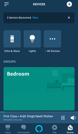
Now we are ready to test our IoT Alexa Home Automation System. So just try saying Alexa, turn on Bedroom light and the Relay one should be turned on.
Now say Alexa, turn off Bedroom light and relay one should turned off. Try giving commands to turn on/off the TV.

You can see the response and state of appliances in serial monitor.
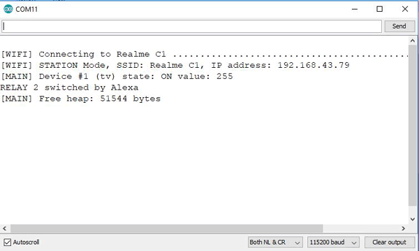
Also note that, fauxmoESP library has some bug and it is under improvement phase. So, sometimes Alexa is unable to discover devices.
So this is how a IoT based Alexa controlled Home Automation System can be made using Arduino.
Find the complete programs and demonstration Video are below. Also check other Iot based Home Automation Projects
ESP8266 Code:
#include <Arduino.h>
#include <ESP8266WiFi.h>
#include "fauxmoESP.h"
#define SERIAL_BAUDRATE 115200
#define WIFI_SSID "********"
#define WIFI_PASS "*******"
#define app1 "bedroom light"
#define app2 "tv"
fauxmoESP fauxmo;
void wifiSetup() {
WiFi.mode(WIFI_STA);
WiFi.begin(WIFI_SSID, WIFI_PASS);
while (WiFi.status() != WL_CONNECTED) {
delay(100);
}
WiFi.SSID().c_str(), WiFi.localIP().toString().c_str());
}
void setup() {
Serial.begin(SERIAL_BAUDRATE);
wifiSetup();
fauxmo.createServer(true); // not needed, this is the default value
fauxmo.setPort(80); // This is required for gen3 devices
fauxmo.enable(true);
fauxmo.addDevice(app1);
fauxmo.addDevice(app2);
fauxmo.onSetState([](unsigned char device_id, const char * device_name, bool state, unsigned char value) {
device_id, device_name, state ? "ON" : "OFF", value);
if ( (strcmp(device_name, app1) == 0) ) {
if (state) {
Serial.print("a");
} else {
Serial.print("b");
}
}
if ( (strcmp(device_name, app2) == 0) ) {
if (state) {
Serial.print("c");
} else {
Serial.print("d");
}
}
});
}
void loop() {
fauxmo.handle();
static unsigned long last = millis();
if (millis() - last > 5000) {
last = millis();
}
}
Arduino Code:
char data;
void setup() {
Serial.begin(115200);
pinMode(4, OUTPUT);
pinMode(5, OUTPUT);
}
void loop() {
if(Serial.available() > 0)
{
data = Serial.read();
Serial.print(data);
Serial.print("\n");
if(data == 'a')
digitalWrite(4, HIGH);
else if(data == 'b')
digitalWrite(4, LOW);
else if(data == 'c')
digitalWrite(5, LOW);
else if(data == 'd')
digitalWrite(5, HIGH);
}
}


