


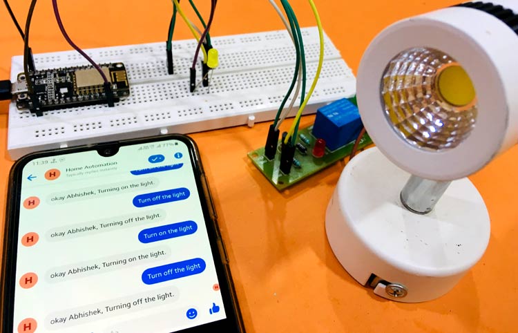
Facebook is one of the most widely used social media application, it is not only used for social networking but also for messaging, video calls, voice calls, market place etc. These features of Facebook can be really helpful in building any IoT based project. Like here we will use Facebook to control the devices in our home remotely. You just need to send a text message to a chatbot which can control lights in your home from any part of the world. We will use ESP8266 NodeMCU hardware and few online applications to build this project.
We previously build few IoT based Home automation projects using different microcontrollers:
- IoT Home Automation using Blynk App using ESP32
- Home Automation with MIT App Inventor and ESP8266
- IoT Based Home Appliances Control with Adafruit IO and Raspberry Pi
- Control Home Appliances with ARTIK Cloud and Raspberry Pi
- Google Assistant Based Home Appliance Control using ESP32 and Adafruit IO
Before going into the details we first learn about the things involved in this project.
ESP8266 NodeMCU
ESP8266 NodeMCU is an open source IoT platform. It includes firmware which runs on the low cost Wi-Fi enabled ESP8266 Wi-Fi SoC from Espressif Systems, and hardware which is based on the ESP-12 module. It has GPIO, SPI, I2C, ADC, PWM AND UART pins for communication and controlling other peripherals attached to it. On board NodeMCU has CP2102 IC which provides USB to TTL functionality.
MQTT
MQTT stands for Message Query Telemetry Transport. MQTT is a TCP/IP based publish and subscribe protocol which is designed for lightweight machine to machine interactions with IOT devices. These devices act as the client who communicates to the server known as broker. A broker is a server which allows clients to send short messages to the broker and receive messages if they are subscribed to certain topic. It acts as a server that handles all the information of the devices that are connected to the server. A client can be either publisher (sending data from device to the server) or subscriber (getting data from the server to the device) of information simultaneously.
Facebook Messenger
Facebook Messenger is a messaging app and a platform which was developed by Facebook. People generally use it to send text, share photos/videos and even make voice or video calls. Regular chats and voice/video chats can be started between individuals or in groups.
Chatfuel
Chatfuel is the leading bot platform for creating AI chatbots for Facebook. People can create AI chat bots which can be used to trigger any event from remote distance. A simple text from you on messenger can add AI features in your projects.
IFTTT
IFTTT stands for IF THIS THAN THAT. It is a free web-based service that allows connecting to web services, applications and devices such as Google, Facebook, Adafruit, Webhooks, Telegram, etc. to automate the tasks. Applets help to combine two services using a trigger and an action. It simply means if something is triggered in one web service then an action will take place in other web service.
Adafruit IO
Adafruit IO is a server by Adafruit Industries. It is a platform for interacting with IOT devices using HTTP and MQTT protocols which helps to store and view data and also helps in controlling the devices.
Working of Facebook Controlled Home Appliances
In this project we will control a home appliance like a lamp using Facebook messenger. On typing certain keywords on the messenger you will be able to control devices in your house. The message will be sent to one chatbot which will trigger respective AI block in the Chatfuel. That block is linked to some JSON API which will send a POST request to the IFTTT. IFTTT will help to link Webhooks and Adafruit to send and store the data to the Adafruit with the help of Webhooks. Webhooks will create an event which will have unique trigger key to trigger the event. The data sent to Adafruit will trigger the toggle button in the dashboard. Adafruit acts as the server for NodeMCU and sends the data to it which in result activate or deactivate the lamp with the help of MQTT.
Circuit Diagram
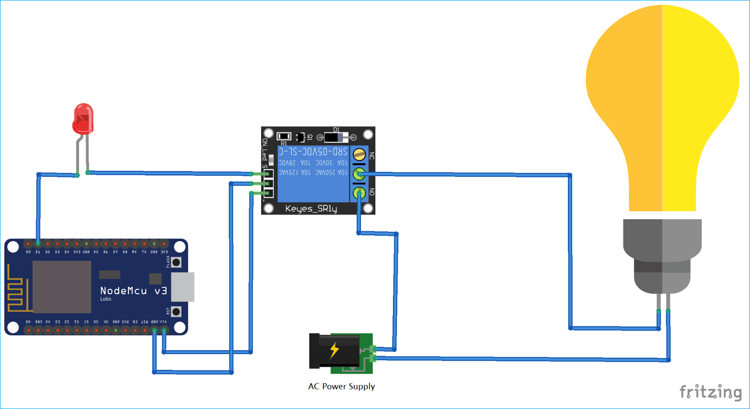
Components Required
- ESP8266 NodeMCU
- Micro USB cable
- Jumper wires
- LED
- Relay
- Lamp or Bulb with bulb holder
- AC power supply
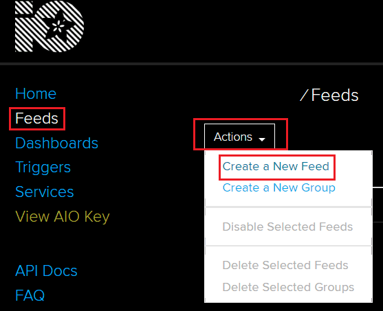
Setup of Adafruit IO for controlling Home Appliances
Open https://io.adafruit.com/ and Click on Get Started for Free. Enter the details and create a new account. After this you will be redirected to the Adafruit IO Homepage. Click on Feeds on left top corner. Now in the Feeds page, click on Action button and then click on Create a New Feed and give some name to the feed. Here we named it “OnOff” name to my Feed.
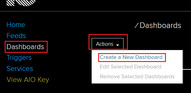
After creating the Feed, Click on the Dashboards in left corner. Now in the Dashboard click on the Actions and then Select Create a New Dashboard. Now give a name to your Dashboard and click on Create, here I gave “Home Automation” name to my Dashboard.
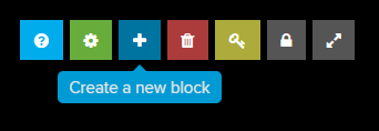
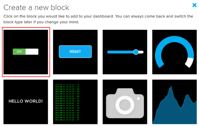
Then click on your newly created dashboard. In your dashboard page you have to create a new block for On/Off toggle button. Click on the plus button in the dashboard page to create a new block and then select the first “Toggle Button”.
Next you will be asked to select the feed for this button as this button will help us feed the data. Tick the checkbox of the Feed (Here my feed is OnOff) and click on Next Step.
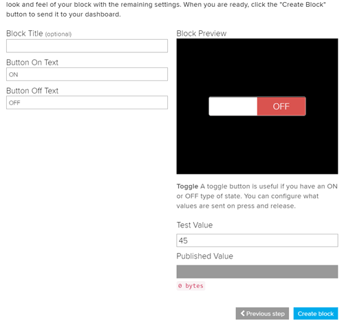
Now give the name for toggle button ON and OFF and Click on Create Block. Now a toggle button will be created on your dashboard which will help us to send the data to our feed.
Setup of IFTTT to Trigger Adafruit Toggle button
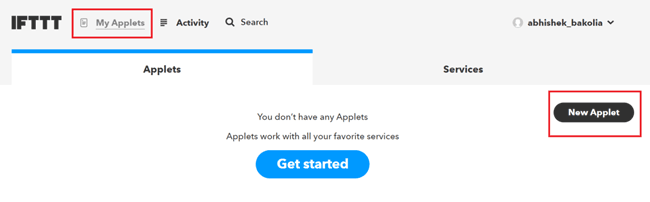
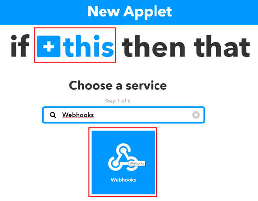
Step 1:- Go to https://ifttt.com/ and sign in with Facebook or Google. After signing in click on My Applets on the top and then click on New Applets.
Step 2:- Then click on “+ this” and search for Webhooks in Choose a service section.
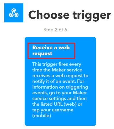
Step 3:- Now click on Receive a web request
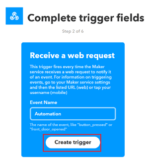
Step 4:- Type any Event Name (“Automation” in my case) then click on trigger (“Automation” in my case).
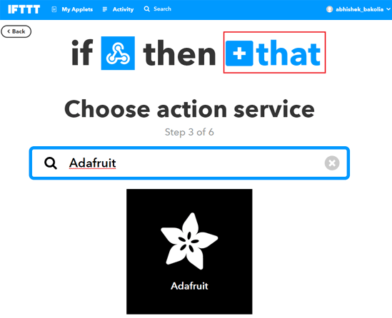
Step 5:- In next page click on “+ that” as mentioned in red box. Search for Adafruit and give the login credentials.
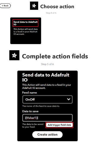
Step 6:- Click on Send data to Adafruit IO. Select the Feed Name created before in Setup of Adafruit IO section. Select value1 by clicking on add ingredient in Data to save and click on Create Action and then click on Finish.
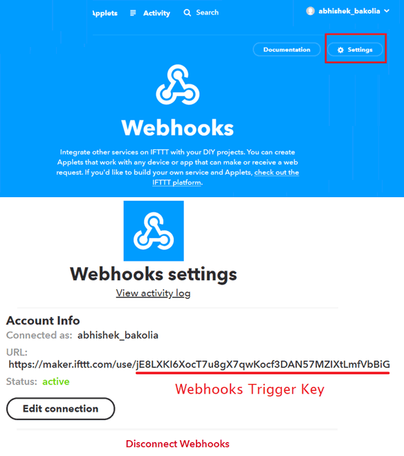
Step 7:- Now go to Webhooks settings and copy the URL in a notepad. This URL contains the Webhooks key with mixed characters which will help to connect Chatfuel to IFTTT.
Setup of Chatfuel with Facebook
Step 1:- Go to https://chatfuel.com/ and click on login with your Facebook Id. After successfully logging it will direct you to the Dashboard page. Click on Create from Template and then My First Bot. Then connect My First Bot to a facebook page that can be created from https://www.facebook.com/pages/creation/.

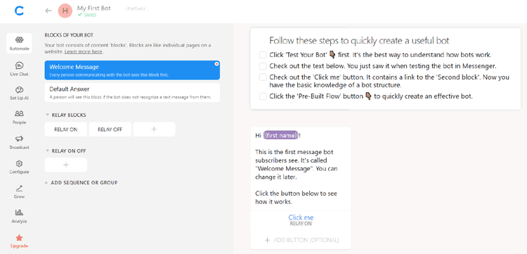
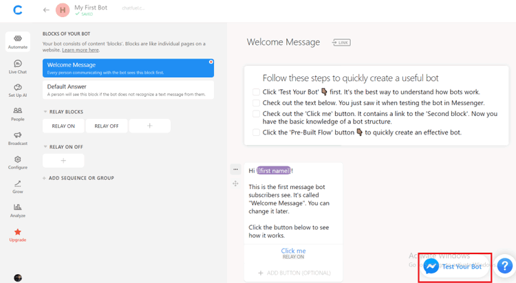
Step 2:- Make a page with any name (“Home Automation” in my case) and connect it to your new bot. After connection you will be directed to your bot page with a welcome message. You can edit this welcome message according to your wish.
Step 3:- Now create two new blocks (here Relay ON and Relay OFF). Then click on Relay ON and select the Text from Add Element. Write the text you want to display on when the user call for the relay on block. Do the same for Relay OFF block.
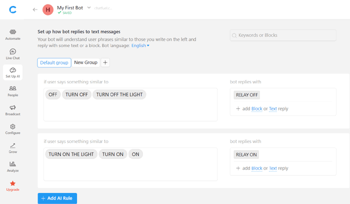
Step 4:- Click on Set Up AI in the left and click on Add AI Rule and Click on Default group. Select the RELAY ON in the bot replies with section. Now add texts in if user says something similar to section. These texts will help to trigger the blocks. Do the same for RELAY OFF button.
Step 5:- Now we have to add JSON API for both RELAY ON and RELAY OFF blocks to link chatfuel with IFTTT. You can test your chatbox by clicking on TEST YOUR BOT and the welcome text will be send to your messenger account.
Chatfuel with IFTTT
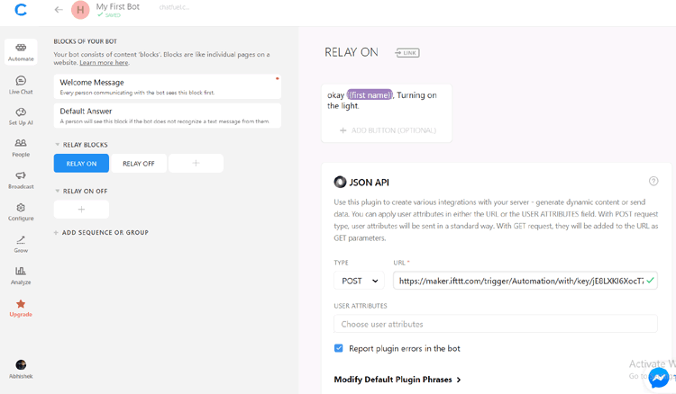
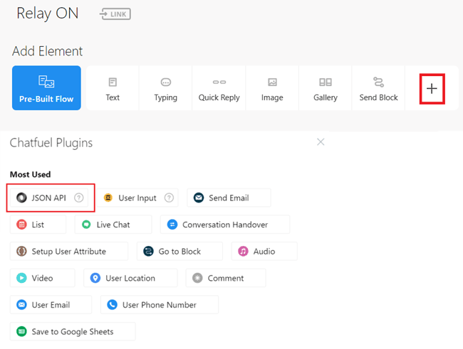
Step 1:- Now we have to make two URLs for both RELAY ON and RELAY OFF buttons. Go to Chatfuel, Select Relay ON and Click on + sign in Add Elements and Select JSON API from Chatfuel Plugins.
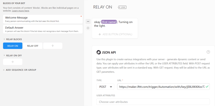
Step 2:- Set type as POST and copy URL1 from below and change the event name and key according to your IFTTT account or you can directly get the URL from your IFTTT account. Do the same for RELAY OFF block.
RELAY ON Block:
RELAY OFF Block:
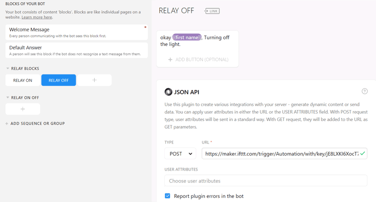
Step 3:- Here are the two URLs which are copied in the JSON API section of RELAY ON and RELAY OFF. This URL contains Event name and Webhooks trigger key. “Automation” is the event name we created in the Webhooks and “jE8LXKI6XocT7u8gX7qwKocf3DAN57MZIXtLmfVbBiG” is the trigger key. Value1=1 is for Relay ON and Value1=0 is for Relay OFF blocks.
Step 4:-Now Chatfuel is ready and is connected to IFTTT.
Step 5:- Make the connections as given in the circuit diagram and upload the Code in the NodeMCU. Wait for some time till it gets connected to Wi-Fi and MQTT broker. Click on Test your bot in Chatfuel, this will direct you to your messenger website where you can test your bot by typing “turn on the relay” or “turn off the relay”. You will get a reply in the messenger with values changing of the toggle button in the real time in your Adafruit dashboard. You will also able to see the change in the state of led as well as lamp or bulb with a tickle sound of the relay.
Code Explanation
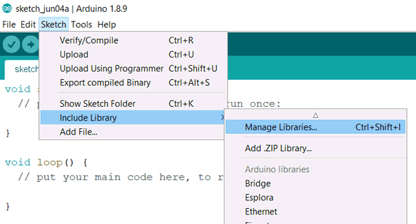
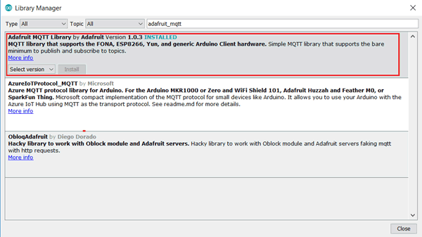
Complete code for this ESP8266 based Facebook home automation is given at the end along with a demonstration video. But before start writing the code, first we need “Adafruit_MQTT.h” library by Adafruit for MQTT connection of NodeMCU with the Adafruit IO server. We can download this library directly from Arduino IDE. Open the Adruino IDE, go to Sketch -> Include Library -> Manage Libraries. Search for “adafruit_mqtt” in Library Manger. Install the latest version as selected in the red box.
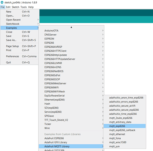
Installing of this library comes with the many in built examples. For this Home Automation project we will use mqtt_esp8266 example. Go to File -> Examples -> Adrafruit MQTT Library -> mqtt_esp8266. Now we will edit the code given in mqtt_esp8266.
Now first include all the required libraries.
#include <ESP8266WiFi.h>
#include "Adafruit_MQTT.h"
#include "Adafruit_MQTT_Client.h"
Replace SSID and password given in code with you Wi-Fi SSID and password.
#define WLAN_SSID   "CircuitLoop"
#define WLAN_PASS   "circuitdigest101"
To connect our client ESP8266 to Adafruit server we will need Adafruit Server link, Adafruit Server port, Adafruit username and Adafruit key. AIO SERVER is “io.adafruit.com” and the port used is 8883 for SSL. In the Setup of Adafruit section I have mentioned procedure to get your Adafruit username and key. All these variables are passed to Adafruit_MQTT_Client mqtt function which helps to establish MQTT connection. Change the feed name given in the Adafruit_MQTT_Subscribe function with the feed name in your Adafruit.
WiFiClient client;
#define AIO_SERVER      "io.adafruit.com"
#define AIO_SERVERPORT  1883                   // use 8883 for SSL
#define AIO_USERNAME        "abhi220897"
#define AIO_KEY             "200c7dcc313b478c99a8cf2d03dc36e3"
Adafruit_MQTT_Client mqtt(&client, AIO_SERVER, AIO_SERVERPORT, AIO_USERNAME, AIO_KEY);
Adafruit_MQTT_Subscribe onoffbutton = Adafruit_MQTT_Subscribe(&mqtt, AIO_USERNAME "/feeds/onoff");
In void setup() function, D1 pin of the NodeMCU is set as the output data pin for the relay. Baud rate of 115200 is set for the displaying data on the serial monitor. Wi-Fi connection is established by passing Wi-Fi credentials in WiFi.begin() function and IP address is printed on the serial monitor on successful connection. MQTT subscription is set up for onoff feed.
#define led D1
void setup() {
  pinMode(led, OUTPUT);
  digitalWrite(led, LOW);
  Serial.begin(115200);
  delay(10);
  Serial.println(F("Adafruit MQTT demo"));
// Connect to WiFi access point.
Serial.println(); Serial.println();
Serial.print("Connecting to ");
Serial.println(WLAN_SSID);
WiFi.begin(WLAN_SSID, WLAN_PASS);
while (WiFi.status() != WL_CONNECTED) {
    delay(500);
    Serial.print(".");
  }
Serial.println();
Serial.println("WiFi connected");
 Serial.println("IP address: ");
Serial.println(WiFi.localIP());
 mqtt.subscribe(&onoffbutton);
}
In void loop(), MQTT_connect() ensures MQTT connection remains alive and connects automatically if gets disconnected. The while waits for incoming subscription packets and when it receives any data String response it converts the response to 1 or 0 and check in if-else statement. If the data received is 1 then we set the D1 pin as high else set it low.
void loop() {
  MQTT_connect();
  Adafruit_MQTT_Subscribe *subscription;
  while ((subscription = mqtt.readSubscription(5000))) {
 if (subscription == &onoffbutton) {
      Serial.print(F("Got: "));
      Serial.println((char *)onoffbutton.lastread);
      String response = (char*)onoffbutton.lastread;
      if (response == "1"){
      digitalWrite(led, HIGH);
      }
      else {
        digitalWrite(led, LOW);
      }
    }
  }
}
Below is the Function for MQTT connection:
void MQTT_connect() {
  int8_t ret;
  // Stop if already connected.
  if (mqtt.connected()) {
    return;
  }
  Serial.print("Connecting to MQTT... ");
  uint8_t retries = 3;
  while ((ret = mqtt.connect()) != 0) { // connect will return 0 for connected
       Serial.println(mqtt.connectErrorString(ret));
       Serial.println("Retrying MQTT connection in 5 seconds...");
       mqtt.disconnect();
       delay(5000);  // wait 5 seconds
       retries--;
       if (retries == 0) {
         // basically die and wait for WDT to reset me
         while (1);
       }
  }
  Serial.println("MQTT Connected!");
}
Finally Connect any home appliance with a Relay module at the D1 port and upload the code given below in the NodeMCU. After connection of NodeMCU with Wi-Fi you can turn on and off the home appliance by toggling the button in your dashboard in Arduino IO.
#include <ESP8266WiFi.h>
#include "Adafruit_MQTT.h"
#include "Adafruit_MQTT_Client.h"
/************************* WiFi Access Point *********************************/
#define WLAN_SSID "CircuitLoop"
#define WLAN_PASS "circuitdigest101"
/************************* Adafruit.io Setup *********************************/
#define AIO_SERVER "io.adafruit.com"
#define AIO_SERVERPORT 1883 // use 8883 for SSL
#define AIO_USERNAME "abhi220897"
#define AIO_KEY "200c7dcc313b478c99a8cf2d03dc36e3"
#define led D1
// Create an ESP8266 WiFiClient class to connect to the MQTT server.
WiFiClient client;
// Setup the MQTT client class by passing in the WiFi client and MQTT server and login details.
Adafruit_MQTT_Client mqtt(&client, AIO_SERVER, AIO_SERVERPORT, AIO_USERNAME, AIO_KEY);
// Setup a feed called 'onoff' for subscribing to changes.
Adafruit_MQTT_Subscribe onoffbutton = Adafruit_MQTT_Subscribe(&mqtt, AIO_USERNAME "/feeds/onoff");
void MQTT_connect();
void setup() {
pinMode(led, OUTPUT);
digitalWrite(led, LOW);
Serial.begin(115200);
delay(10);
Serial.println(F("Adafruit MQTT demo"));
// Connect to WiFi access point.
Serial.println(); Serial.println();
Serial.print("Connecting to ");
Serial.println(WLAN_SSID);
WiFi.begin(WLAN_SSID, WLAN_PASS);
while (WiFi.status() != WL_CONNECTED) {
delay(500);
Serial.print(".");
}
Serial.println();
Serial.println("WiFi connected");
Serial.println("IP address: "); Serial.println(WiFi.localIP());
// Setup MQTT subscription for onoff feed.
mqtt.subscribe(&onoffbutton);
}
uint32_t x=0;
void loop() {
// Ensure the connection to the MQTT server is alive (this will make the first
// connection and automatically reconnect when disconnected). See the MQTT_connect
// function definition further below.
MQTT_connect();
// this is our 'wait for incoming subscription packets' busy subloop
// try to spend your time here
Adafruit_MQTT_Subscribe *subscription;
while ((subscription = mqtt.readSubscription(5000))) {
if (subscription == &onoffbutton) {
Serial.print(F("Got: "));
Serial.println((char *)onoffbutton.lastread);
String response = (char*)onoffbutton.lastread;
if (response == "1"){
digitalWrite(led, HIGH);
}
else {
digitalWrite(led, LOW);
}
}
}
}
// Function to connect and reconnect as necessary to the MQTT server.
// Should be called in the loop function and it will take care if connecting.
void MQTT_connect() {
int8_t ret;
// Stop if already connected.
if (mqtt.connected()) {
return;
}
Serial.print("Connecting to MQTT... ");
uint8_t retries = 3;
while ((ret = mqtt.connect()) != 0) { // connect will return 0 for connected
Serial.println(mqtt.connectErrorString(ret));
Serial.println("Retrying MQTT connection in 5 seconds...");
mqtt.disconnect();
delay(5000); // wait 5 seconds
retries--;
if (retries == 0) {
// basically die and wait for WDT to reset me
while (1);
}
}
Serial.println("MQTT Connected!");
}


