


Have you ever thought of controlling your Arduino board remotely without using any shield or module like ESP8266 and Bluetooth? Yes, it is possible with the help of the Blynk App and its server. Blynk is a very popular IoT platform to build IoT projects like:
- IoT Controlled LED using Blynk and ESP8266 (Node MCU)
- IoT based Temperature and Humidity Monitoring using BLYNK, ESP8266, and DHT11 Sensor
- IoT Home Automation using Blynk App using ESP32
- IoT based Home Automation using Blynk App and Raspberry Pi
- IoT Controlled LED using ESP32 with Blynk App
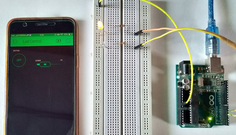
Here in this project, we will control two LEDs remotely using the Blynk app. Both the LEDs will be connected with Arduino, one LED will be made on and off, and another LED’s brightness will be controlled using Blynk App.
What is Blynk?
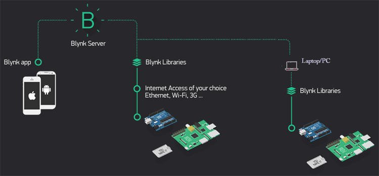
Blynk is an IoT platform that allows us to quickly build projects for controlling and monitoring the data using Android and iOS devices. We can create a project dashboard and add widgets like buttons, displays, sliders, etc. for controlling microcontrollers and other peripherals. Using these widgets, we can control the devices and can monitor the sensor data on the phone screen.
We have previously covered the Blynk app with other IoT-based Microcontrollers, follow the link to find them all.
Features of Blynk:
1. You can add a notifications service using the Blynk app without using any third-party platform like IFTTT. For example, you can post the data on Twitter and get the e-mail when something reaches its threshold. This can be possible just by configuring the Blynk app.
2. In IoT projects, the hardware part is easy as compare to the software part. But using Blynk, the software part also becomes easier than the hardware. There is very less coding required and all the code is included in its library. Blynk is perfect for building simple projects.
3. Most of the microcontroller available in the market is supported by Blynk and these microcontrollers can be controlled using Blynk app via Wi-fi, BLE, USB, GSM, and Ethernet.
4. You can create your own local Blynk server to control the appliances locally just by using few steps and can control easily using the Blynk app.
5. One of the most interesting features of Blynk is the use of virtual pins. Virtual Pin is a concept invented by Blynk to provide the exchange of any data between hardware and the Blynk mobile app. These pins are different from Digital and Analog pins, they don’t have any physical properties.
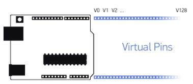
So, if you want any data from the virtual pin, the Blynk app will send the data to a defined virtual pin and then this data can be accessed on MCU pins. Also, the data can be sent from the Blynk app to any virtual pin, and then the data can be easily accessed on the app.
In this project, we will also use a virtual pin to control Arduino.
Materials Required
- Arduino Uno
- Arduino Uno USB cable
- Two LEDs
- Jumper Wires
- Breadboard
Circuit Diagram
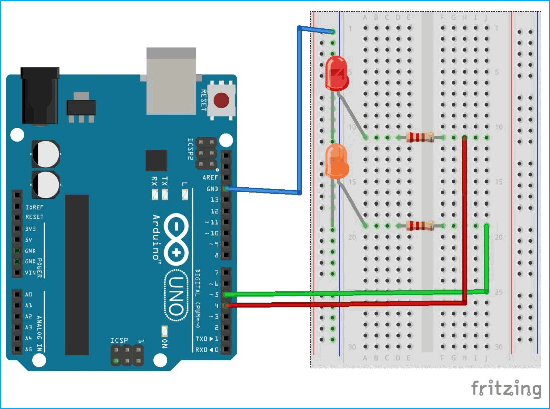
The circuit diagram is very simple, just connect one LED to PWM pin (5) and the other LED to digital pin 4 of Arduino Uno.
Now, let's start by installing Blynk App and Libraries.
Installing and Configuring Blynk App to control LED
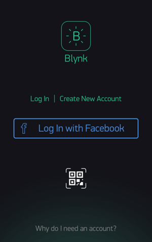
1. Download the Blynk app from the play store. It is available for both Android and iOS users. Open the app and create an account by entering your e-mail ID and password.
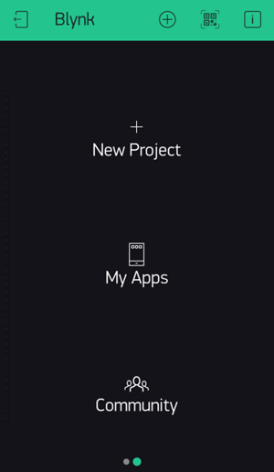
2. Now, we will create a New Project. So, tap on New Project.
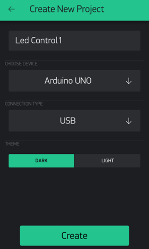
3. Give a Project name and Choose the Device as Arduino UNO and Connection Type as USB because we are using serial communication to talk with Arduino and Blynk Server. Now, click on Create as shown below.
4. After Creating the Project, you will receive an Auth Token on registered mail id. This token will be used in the Code. Complete code is given at the end of this tutorial.
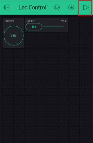
5. Now an empty dashboard will be shown where we will place all the required widgets i.e. buttons, displays, sliders, etc. Tap on + sign. All the available widgets are shown here. You can explore all the widgets and can use them according to your requirements.
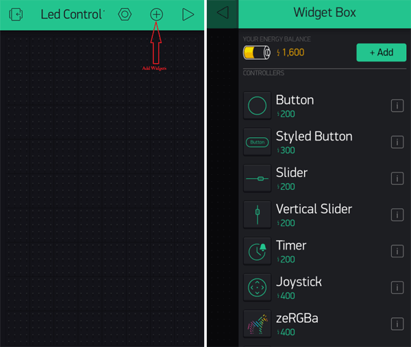
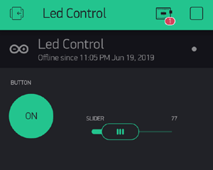
In this tutorial, we will toggle an LED and control the brightness of other LEDs. So, we need a button and a slider to control the brightness.
Select the Button Widget and type of slider (H or V) by tapping on it.
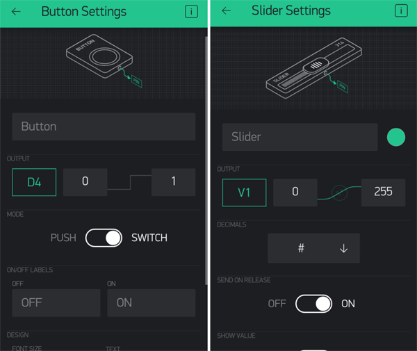
6. Now, set the properties of both widgets. Tap on the button on the dashboard. Choose Output on D4 and mode as Switch then go back to dashboard and tap on the slider. Choose Output pin on Virtual pin V1 and all properties remain the same.
Now we are ready with the Blynk app. Let's Start programming Arduino board for working with the Blynk app, for this there is a library available for Arduino.
Installing Blynk Library in Arduino
Before start writing the code for Arduino Uno, we will first install the Blynk Library in Arduino IDE:
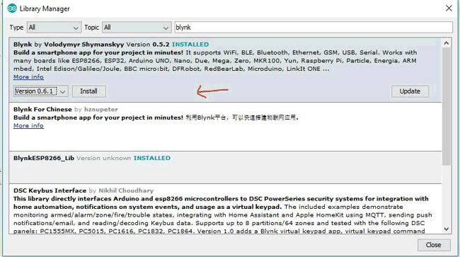
1. To install the library, Go to Sketch -> Include Libraries -> Manage Libraries. Then search for Blynk and install the latest version as shown below.
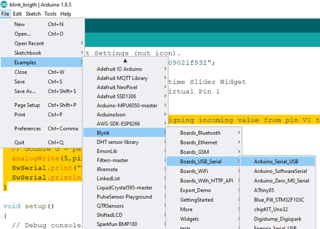
2. Now, we will modify an example code. So, open Examples->Blynk->Boards_USB_Serial->Arduino_Serial_USB.
Let’s see the given code and try to understand it.
Programming Arduino for Blynk App
Complete code with a demonstration video is given at the end of this tutorial. Here we have explained the code step-by-step.
1. First, declare macros using #define as required in the code. Here macro BLYNK_PRINT is defined as DebugSerial for printing purpose.
#define BLYNK_PRINT DebugSerial
2. Now, include header files for software serial and Blynk functions and make a instance for Software serial as DebugSerial.
#include <SoftwareSerial.h>
SoftwareSerial DebugSerial(2, 3);    // RX, TX
#include <BlynkSimpleStream.h>
3. Store that auth token in the char array.
char auth[] = "YourAuthToken";
4. In setup() function, initialize software serial, inbuilt serial and Blynk with baud rate 9600. Function blynk.begin() takes two arguments namely Serial and auth token.
void setup()
{
DebugSerial.begin(9600);
Serial.begin(9600);
Blynk.begin(Serial, auth);
}
5. In void loop() function, there should be very minimum code so that Blynk can work without any interrupt or loss of data. This is because when you put something in void loop function like getting sensor reading from MCU or from the smartphone, it executes million times and this data uploads on the Blynk server which means the Blynk cloud will flooded with tons of messages and server will consider this as Spams so the Blynk cloud will automatically terminate the connection. Also, avoid using the delay function in the loop because it completely stops the functioning of MCU and the connection will close in this situation also.
The best choice for getting the sensor data from Arduino is by using the timers. Initialize the timers in the setup function and define a function to perform the task.
There will be a bare minimum function required - Blynk.run() and timer function can handle all the tasks of getting the data and sending it to the server. But in this tutorial, we are not sending any data so timers are not required.
void loop()
{
  Blynk.run();
}
6. The code for toggling the LED is inbuilt in the Blynk.run() function but we have to make a function for getting the slider value from a smartphone. There are two functions for sending and receiving the data which are BLYNK_READ() and BLYNK_WRITE(). These functions take virtual pins as an input argument to read and write the data. Therefore we have to use the BLYNK_WRITE function to write the data on virtual pin V1 from the Blynk app.
Now, assign the incoming value from pin V1 to a variable, param.asInt() function returns the received value as integer. If the received value is not integer you can use float, double or string.
param.asFloat();  // get value as a Float
param.asDouble(); // get value as a Double
param.asStr();    // get value as a String
Then put this value in the PWM pin of Arduino using the analogWrite() function.
BLYNK_WRITE(V1)
{
int pinValue = param.asInt();
analogWrite(5,pinValue);
}
That’s it. We have done with the coding part. Now, plug-in your Arduino board using a USB cable and check the COM port of your board in Device manager.
Script for Internet Connection:
Here we are not using any module with Arduino board but a working internet connection is needed to send and receive data over the cloud so there is a script included in the Blynk library that can access our laptop/PC internet connection. Therefore, this script takes the data from the Arduino board through serial communication and uploads the data on Blynk cloud using the laptop internet connection. We have to run this script to start the operation.
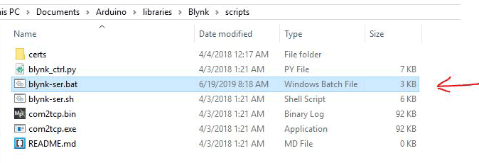
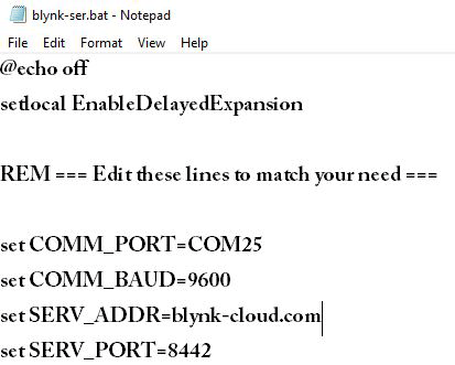
This script can be found in the Arduino directory which is in the Documents folder, Go to Libraries -> Blynk -> Scripts. There is a file named blynk-ser.bat which is the required script. Edit this script with the COM port of the Arduino board and Blynk cloud port number.
Open the script using notepad and replace the following things. You have to replace only with your COM port and save the file, all other things remain the same.
set COMM_PORT= COM(port_no.)       //e.g. COM25
set COMM_BAUD=9600
set SERV_ADDR=blynk-cloud.com
set SERV_PORT=8442
Testing - Controlling the Arduino Remotely using Blynk App
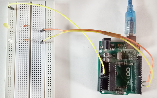
Now, we are all set to control the Arduino GPIO pin with Blynk app. Make sure you have connected both the LEDs and have a working internet connection in your laptop and smartphone.
For running the project, double click on the script and it will start executing. Now, open the app. Tap on the play button in the upper right corner.
Then tap on the LED button to turn on the LED and again tap on it to turn the LED off.
Similarly, move the slider to vary the brightness of the LED.
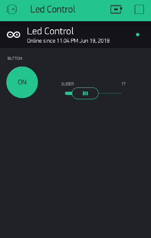
If you see a red dot on the board icon in the app, it means there is no internet connection on either side so check the internet connection and try again.
This is how easily an Arduino board can be controlled remotely using Blynk app. Check the complete code and demo video below.
#define BLYNK_PRINT DebugSerial
#include <SoftwareSerial.h>
SoftwareSerial DebugSerial(2, 3); // RX, TX
#include <BlynkSimpleStream.h>
char auth[] = "YourAuthToken";
BLYNK_WRITE(V1)
{
int pinValue = param.asInt();
analogWrite(5,pinValue);
}
void setup()
{
DebugSerial.begin(9600);
Serial.begin(9600);
Blynk.begin(Serial, auth);
}
void loop()
{
Blynk.run();
}


