


It’s been almost three years since Amazon released the Amazon ECHO voice controlled speakers and the popularity of the speaker has continued to soar because of astounding performance of the Alexa Voice Service, and the fact that the platform was opened up to developers has led to the development of Alexa compatible devices by top electronics manufacturers and the birth of several Alexa/Amazon echo based tech start-ups.
There are many Alexa enabled smart lightings are available in the market but they are a little bit costly, so here in this tutorial we learn to build our own Alexa controlled Light using ESP12E NodeMCU. In this Alexa controlled home automation project, we will emulate the WeMo switch by using ESP module.
WeMo is the name of series of IoT products developed by Belkin company, it mainly include WeMo switch which can be controlled from anywhere over internet. So connecting any AC appliance with WeMo switch makes that device IoT enabled. IoT based Home automation is very popular nowadays and we have previously done many IoT Home Automation Projects using different controllers like Raspberry Pi, ESP8266, Arduino etc.
Materials Required
- NodeMCU ESP-12E (ESP8266 can also be used)
- Relay Modules
- AC Bulb
- Jumper Wires
Circuit Diagram
Connections for this Amazon Echo controlled Home Automation is shown below:

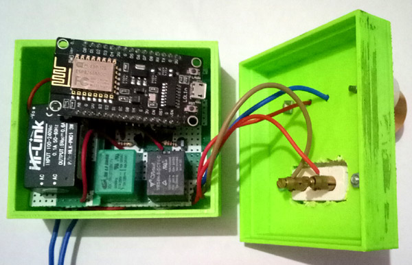
Here two relay modules are connected to NodeMCU to control two Home appliances. A 5v power supply from an adaptor or 5v AC to DC converter can be used to power the circuit. I am using HiLink 5v SMPS to provide power.
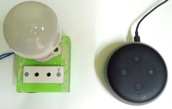
The whole setup is assembled in a 3D printed box to give it a smart appliance board look. There is a bulb holder and a socket to plug an appliance like TV. The assembled box is shown in the image below.
Ways to control NodeMCU with Amazon Echo Dot
There are several methods from which we can control our ESP. They are listed below with features
- Using Amazon Alexa Skills: This method is for developers who knows how to create an skill and it requires knowledge of AWS services. It’s a complex and time consuming method.
- Using Third Party Services: This method is very popular and we have used this many times. Using third party services like IFTTT we can trigger any action whenever we receive commands from Alexa. This method is easy but requires integration of two services like Amazon Alexa + Webhooks.
- Using already built skills: There are some Smart home skills which are already available in Alexa skill store. Sinric is one of them which is used to make any appliance a custom Alexa enabled Smart home device. Library for the ESP boards are available on github and with some configuration on Sinric website we can control our appliances using Alexa. But the code for ESP boards is little difficult to understand for the beginners but it is easy to use.
- Using virtual switch emulation libraries: Alexa has built in support for some home appliances like Phillips Hue and Belkin WeMo. So some developers emulated these platforms and developed their own version of Phillips hue or WeMo by spoofing the response to behave like a supported device such as the WeMo.
Here in this tutorial we are using this virtual switch emulation technique so lets see this method in detail.
WeMo Switch Emulation using Amazon Alexa Echo Dot
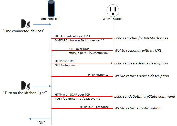
The WeMo devices use UPnP (Universal Plug and Play protocol) to send and receive data over the network. We can easily track this communication between device and Wi-Fi network using Wireshark network tool. Wireshark is used to collect packets while the communication takes place between WeMo device and Echo dot speaker. Developer found that Device Detection Function starts with the Echo searching for WeMo devices using UPnP. Then the device responds to the Echo with the device’s URL using HTTP over UDP. Echo requests the device to send the description of itself in HTTP format.
Now, Echo detects the device and establishes a connection. The Echo and the WeMo connects over the HTTP and issues a “SetBinaryState” (On/OFF) command. Then WeMo takes that command and sends a confirmation via HTTP. The complete flow chart emulating a WeMo switch using Alexa is given below
Now, this information can be used to set up our own WeMo virtual cloud. So, a script was made in the same way to emulate the Phillips or WeMo devices by developers and can be used with any ESP device.
FauxmoESP library is one of them which is easy to use and emulates Phillips devices. Using this library we can make many virtual devices and control our appliances using Alexa.
So here we are using virtual switch emulation technique as it is easy to implement and need less coding.
Downloading and Installing Required Libraries for WeMo Emulation
As we will create multiple virtual connections environment on ESP so we need to install fauxmoESP along with Asynchronous TCP library.
1. For ESP8266 download the Asynchronous TCP library from this link and for ESP32 download it from this link.
2. Then download fauxmoESP library from this link .
3. Now, unzip these files in libraries folder in your Arduino directory which can be found in Documents folder. Also, rename these folders as oseperez-fauxmoesp-50cbcf3087f to xoseperez_fauxmoesp and ESPAsyncTCP-master to ESPAsyncTCP.
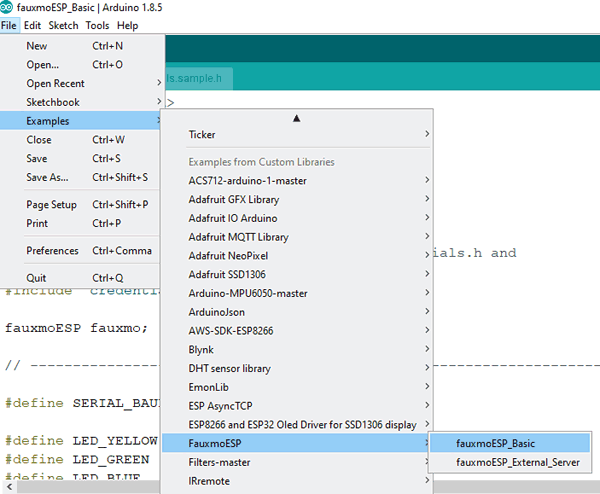
4. There is an example code in fauxmoESP for controlling appliances we have to modify this example. Open Arduino IDE and go to Examples -> FauxmoESp -> fauxmoESP_Basic.
Before starting with the coding part, make sure you have installed ESP board files. If you don’t have board files then follow our previous tutorials on getting started with ESP using Arduino IDE.
Code and working Explanation
Complete code with a working video for this Alexa controlled Home appliances is given at the end of this tutorial, here we are explaining the complete program to understand the working of the project.
First, include important header files for ESP board and fauxmoESP. There different header files for ESP8266 and ESP32 but in this example code both libraries are included so this code will work for both the boards. Also, define pin number for the relays.
#include <Arduino.h>
#ifdef ESP32
  #include <WiFi.h>
//  #define RELAY_PIN_1 12
//  #define RELAY_PIN_2 14
#else
  #include <ESP8266WiFi.h>
  #define RELAY_PIN_1 4
  #define RELAY_PIN_2 14
#endif
#include "fauxmoESP.h"
Define baud rate of 115200 and Wi-Fi-SSID and Password. Also, make an instance for fauxmoESP as fauxmo so that we can use this in our code.
#define SERIAL_BAUDRATE 115200
#define WIFI_SSID "*******"
#define WIFI_PASS "*******"
fauxmoESP fauxmo;
Make a separate function for Wi-Fi setup so that it can be called in void setup function. Make the WiFi mode as station mode and pass the SSID and Password in WiFi.begin() function. Wait for the connection to establish and display the IP of ESP.
void wifiSetup() {
  WiFi.mode(WIFI_STA);
  Serial.printf("[WIFI] Connecting to %s ", WIFI_SSID);
  WiFi.begin(WIFI_SSID, WIFI_PASS);
  while (WiFi.status() != WL_CONNECTED) {
    Serial.print(".");
..
..
}
In void setup() function, pass the baud rate to serial.begin function and call the wifisetup function.
void setup() {
  Serial.begin(SERIAL_BAUDRATE);
  Serial.println();
  wifiSetup();
Make relay pins high or low by default.
  pinMode(RELAY_PIN_1, OUTPUT);
  digitalWrite(RELAY_PIN_1, HIGH);
  pinMode(RELAY_PIN_2, OUTPUT);
  digitalWrite(RELAY_PIN_2, HIGH);
Now, fauxmoESP has to create its own webserver, for this pass true in createserver function, enable function and set port number as 80. If you make false in enable function then it will prevent the devices from being discovered and switched.
  fauxmo.createServer(true);
  fauxmo.setPort(80);
fauxmo.enable(true);
Add devices using fauxmo.addDevice() function. The argument will be the name of your device that you will used to ask Alexa to switch it on/off.
  fauxmo.addDevice(bedroom_light);
  fauxmo.addDevice(tv);
Now, make a function when a command is received from Alexa. In this function we will compare the string with the device name when it is matched then change the state of AC appliance according to the command given.
  fauxmo.onSetState([](unsigned char device_id, const char * device_name, bool state, unsigned char value) {
    if ( (strcmp(device_name, bedroom_light) == 0) ) {
      if (state) {
        digitalWrite(RELAY_PIN_1, LOW);
      } else {
        digitalWrite(RELAY_PIN_1, HIGH);
      }
    }
}
Similarly, do for the second AC Appliance.
In void loop() function, just check for the incoming packets from Alexa server using fauxmo.handle function and it will take the actions using onSetstate() function .
void loop() {
  fauxmo.handle();
..
}
That’s it.
Finally upload the complete code (given at the end) in NodeMCU after connecting the circuit as per the circuit diagram shown above. Also, note that the Wi-Fi network should remain same for both the NodeMCU and Amazon echo dot.
Select the correct board and port number from Tools menu and hit the upload button. You can open serial monitor in Arduino IDE to see whats happening inside the code. Make the baud rate 115200 in serial monitor.
Testing the Alexa Home Automation System
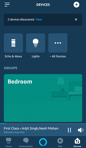
Now, try saying Alexa, Discover Devices. Alexa will respond like Starting discovering… I found two devices, try saying “Alexa, turn on Bedroom light”.
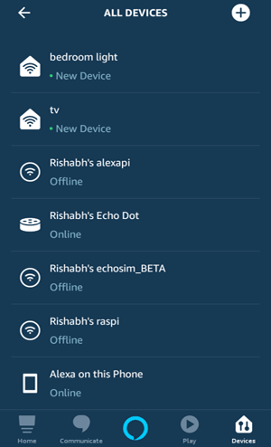
Alternatively, you can discover these devices in your Alexa app. Tap on + sign and then discover devices. You should see two devices namely Bedroom light and TV.
Now we are ready to test our IoT Alexa Home Automation System. So just try saying Alexa, turn on Bedroom light and the Relay one should be turned on.
Now say Alexa, turn off Bedroom light and relay one should turned off. Try giving commands to turn on/off the TV.
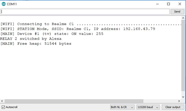
You can see the response and state of appliances in serial monitor.
So this is how a IoT based Alexa controlled Home Automation System can be made by emulating WeMo Switch using ESP12E NodeMCU.
Find the complete program and demonstration Video are below. Also check other Iot based Home Automation Projects.
#include <Arduino.h>
#ifdef ESP32
#include <WiFi.h>
#define RELAY_PIN_1 12
#define RELAY_PIN_2 14
#else
#include <ESP8266WiFi.h>
//#define RF_RECEIVER 5
#define RELAY_PIN_1 4
#define RELAY_PIN_2 14
#endif
#include "fauxmoESP.h"
#define SERIAL_BAUDRATE 115200
#define WIFI_SSID "*******"
#define WIFI_PASS "*********"
#define app1 "bedroom light"
#define app2 "tv"
fauxmoESP fauxmo;
void wifiSetup() {
// Set WIFI module to STA mode
WiFi.mode(WIFI_STA);
Serial.printf("[WIFI] Connecting to %s ", WIFI_SSID);
WiFi.begin(WIFI_SSID, WIFI_PASS);
while (WiFi.status() != WL_CONNECTED) {
Serial.print(".");
delay(100);
}
Serial.println();
Serial.printf("[WIFI] STATION Mode, SSID: %s, IP address: %s\n", WiFi.SSID().c_str(), WiFi.localIP().toString().c_str());
}
void setup() {
// Init serial port and clean garbage
Serial.begin(SERIAL_BAUDRATE);
Serial.println();
// Wi-Fi connection
wifiSetup();
pinMode(RELAY_PIN_1, OUTPUT);
digitalWrite(RELAY_PIN_1, HIGH);
pinMode(RELAY_PIN_2, OUTPUT);
digitalWrite(RELAY_PIN_2, HIGH);
fauxmo.createServer(true);
fauxmo.setPort(80);
fauxmo.enable(true);
fauxmo.addDevice(app1);
fauxmo.addDevice(app2);
fauxmo.onSetState([](unsigned char device_id, const char * device_name, bool state, unsigned char value) {
Serial.printf("[MAIN] Device #%d (%s) state: %s value: %d\n", device_id, device_name, state ? "ON" : "OFF", value);
if ( (strcmp(device_name, app1) == 0) ) {
Serial.println("RELAY 1 switched by Alexa");
if (state) {
digitalWrite(RELAY_PIN_1, LOW);
} else {
digitalWrite(RELAY_PIN_1, HIGH);
}
}
if ( (strcmp(device_name, app2) == 0) ) {
Serial.println("RELAY 2 switched by Alexa");
if (state) {
digitalWrite(RELAY_PIN_2, LOW);
} else {
digitalWrite(RELAY_PIN_2, HIGH);
}
}
});
}
void loop() {
fauxmo.handle();
static unsigned long last = millis();
if (millis() - last > 5000) {
last = millis();
Serial.printf("[MAIN] Free heap: %d bytes\n", ESP.getFreeHeap());
}
}


