


The fall detection system is very useful for elderly people. It can notify the concerned person or family member whenever it detects any fall and can reduce the risk of delayed medical attention. This has led to the development of many different types of automated fall detection systems. Nowadays, you can find fall detectors in smartwatches, fitness trackers, and other types of wearables.
So in this tutorial, we are going to build a fall detection device using NodeMCU and MPU6050 sensor module. MPU6050 sensor module features a gyroscope and an accelerometer. The gyroscope is used to determine the orientation and the accelerometer provides information about the angular parameter such as the three-axis data. To detect the fall, we will compare the acceleration magnitude with the threshold value. If the fall is detected, the device will send an SMS to the concerned person. NodeMCU is used here as a microcontroller and Wi-Fi module to connect with IFTTT to send SMS.
Components Required
- NodeMCU ESP8266
- MPU6050 Accelerometer
- Buzzer
- Connecting Wires
Circuit Diagram
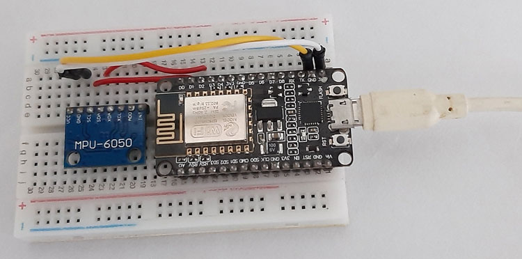
Circuit Diagram for IoT based Fall Detector using NodeMCU is given below.
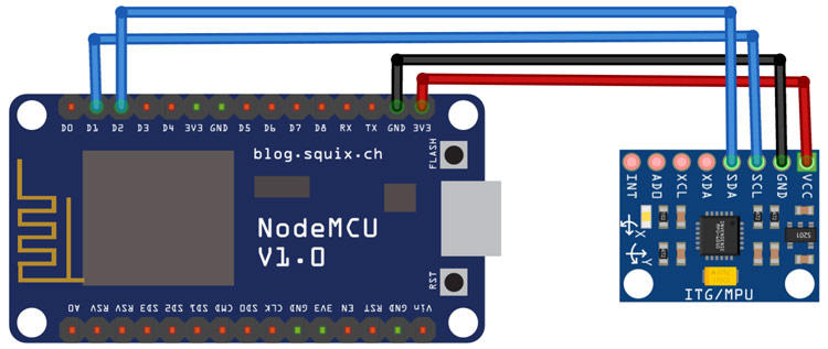
The MPU6050 works on the I2C protocol, so we only need two wires to interface NodeMCU and MPU6050. The SCL and SDA pins of MPU6050 are connected to D1 and D2 pins of NodeMCU, while VCC and GND pins of MPU6050 are connected to 3.3V and GND of NodeMCU. We previously used MPU6050 to build gesture controlled robot.
MPU6050 Sensor Module
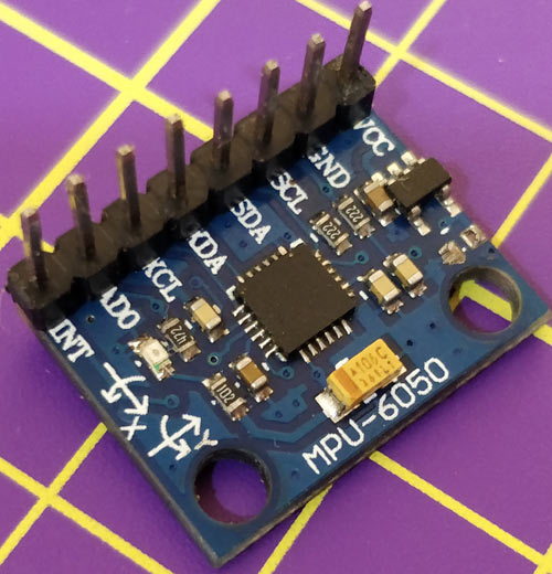
The MPU6050 sensor module is complete 6-axis (3-axis Accelerometer and 3-axis Gyroscope) Micro-Electro-Mechanical Systems (MEMS) that is used to measure acceleration, velocity, orientation, displacement, and many other motion-related parameters. Apart from this, it also has an additional on-chip Temperature sensor.
The MPU6050 module is small in size and has low power consumption, high repetition, high shock tolerance, and low user price points. The MPU6050 comes with an I2C bus and Auxiliary I2C bus interface and can easily interfere with other sensors such as magnetometers and microcontrollers.
IFTTT Setup for Fall Detector
IFTTT (If This Then That) is a web-based service by which we can create chains of conditional statements, called applets. Using these applets, we can send Emails, Twitter, Facebook notifications. Here in this project, we are using IFTTT to send message notifications when the device detects a fall.
To use the IFTTT, sign in to your IFTTT account if you already have one or create an account.
Now search for ‘Webhooks’ and click on the Webhooks in Services section.

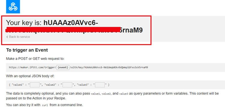
Now, in the Webhooks window, click on ‘Documentation’ in the upper right corner to get the private key.
Copy this key. It will be used in the program.
After getting the private key, now create an applet using Webhooks and Email services. To create an applet, click on your profile and then click on ‘Create.’

Now, in the next window, click on the ‘This’ icon.

Now search for Webhooks in the search section and click on ‘Webhooks.’

Now choose ‘Receive a Web Request’ trigger and in the next window, enter the event name as fall_detect and then click on create a trigger.
Now to complete the applet, click on ‘That’ to create a reaction for the fall_detect event.

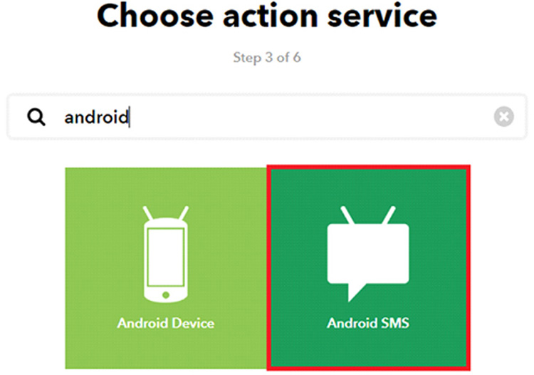
Here we are reacting to fall_detect event by sending a message. For that search for ‘Android device’ in the search section and choose ‘Android SMS.’
Now, it will ask you to enter the phone number and message body. Enter the Mobile Number and the message body and then click on ‘create action’ to complete the process.

Now we will create another applet to play a specific song when the fall is detected.
For this, follow the same procedure as above but instead of ‘Android SMS’, click on ‘Android Device’ and then click on ‘Play a Specific Song’
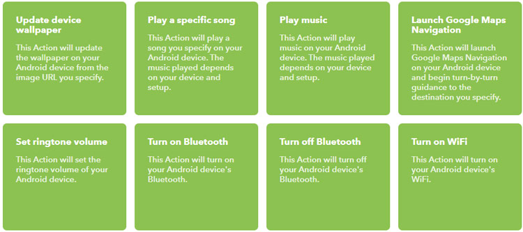
In the next step, enter the song name and then click on Create.
Code Explanation
The complete code for Fall Detector using NodeMCU is given at the end of the page. Here we are explaining some important parts.
As usual, start the code by including all the required libraries. The Wire.h library allows you to communicate with I2C / TWI devices while ESP8266.h library provides NodeMCU specific Wi-Fi routines that we are calling to connect to the network.
#include <Wire.h>
#include <ESP8266WiFi.h>
In the next lines, enter the Wi-Fi Name and password and IFTTT account credentials.
const char *ssid =
"Galaxy-M20"; // Enter your Wi-Fi Name
const char *pass = "ac312124"; // Enter your Wi-Fi Password
void send_event(const char *event);
const char *host = "maker.ifttt.com";
const char *privateKey = "hUAAAz0AVvc6-NW1UmqWXXv6VQWmpiGFxx3sV5rnaM9";
Inside the void setup(), initialize the baud rate, the wire library, and the data transmission through the power management register.
Serial.begin(115200);
pinMode(buzzer, OUTPUT);
Wire.begin();
Wire.beginTransmission(MPU_addr);
Wire.write(0x6B);
Wire.write(0);
Now inside the void loop(), read the MPU6050 sensor data. 2050, 77, 1947 are values for calibration of an accelerometer. Same for gyroscope, add the calibration values in the original values.
ax = (AcX-2050)/16384.00;
ay = (AcY-77)/16384.00;
az = (AcZ-1947)/16384.00;
gx = (GyX+270)/131.07;
gy = (GyY-351)/131.07;
gz = (GyZ+136)/131.07;
After getting the accelerometer and gyroscope values, calculate the amplitude vector of the accelerometer values.
float Raw_Amp = pow(pow(ax,2)+pow(ay,2)+pow(az,2),0.5);
 int Amp = Raw_Amp * 10; // Mulitiplied by 10 bcz values are between 0 to 1
 Serial.println(Amp);
This program first checks if the accelerometer values exceed the lower threshold, if yes, then it waits for 0.5 seconds and checks for the higher threshold. If the accelerometer values exceed the higher threshold, then it checks for the gyroscope values to calculate the change in orientation. If there is a sudden change in orientation, then it waits for 10 seconds and checks if the orientation remains the same. If yes, then it activates the Fall Detector alarm.
if (Amp<=2 && trigger2==false)
{                          //if amplitude breaks lower threshold (0.4g)
   trigger1=true;
   Serial.println("TRIGGER 1 ACTIVATED");
   }
 if (trigger1==true)
{
   trigger1count++;
   if (Amp>=12)
{                         //if AM breaks upper threshold (3g)
     trigger2=true;
     Serial.println("TRIGGER 2 ACTIVATED");
     trigger1=false; trigger1count=0;
     }
 }
 if (trigger2==true)
{
   trigger2count++;
   angleChange = pow(pow(gx,2)+pow(gy,2)+pow(gz,2),0.5); Serial.println(angleChange);
   if (angleChange>=30 && angleChange<=400)
{                        //if orientation changes by between 80-100 degrees
     trigger3=true; trigger2=false; trigger2count=0;
     Serial.println(angleChange);
     Serial.println("TRIGGER 3 ACTIVATED");
       }
   }
 if (trigger3==true)
{
    trigger3count++;
    if (trigger3count>=10)
{
       angleChange = pow(pow(gx,2)+pow(gy,2)+pow(gz,2),0.5);
                       //delay(10);
       Serial.println(angleChange);
       if ((angleChange>=0) && (angleChange<=10))
{                     //if orientation changes remains between 0-10 degrees
           fall=true; trigger3=false; trigger3count=0;
           Serial.println(angleChange);
             }
       else
{                    //user regained normal orientation
          trigger3=false; trigger3count=0;
          Serial.println("TRIGGER 3 DEACTIVATED");
       }
     }
  }
 if (fall==true)
{                  //in event of a fall detection
   Serial.println("FALL DETECTED");
   send_event("fall_detect");
   fall=false;
   }
Inside the mpu_read loop(), read all the six registers for the X, Y, and Z axes of Accelerometer and Gyroscope.
AcX=Wire.read()<<8|Wire.read(); // 0x3B (ACCEL_XOUT_H) & 0x3C (ACCEL_XOUT_L) AcY=Wire.read()<<8|Wire.read(); // 0x3D (ACCEL_YOUT_H) & 0x3E (ACCEL_YOUT_L)
AcZ=Wire.read()<<8|Wire.read(); // 0x3F (ACCEL_ZOUT_H) & 0x40 (ACCEL_ZOUT_L)
GyX=Wire.read()<<8|Wire.read(); // 0x43 (GYRO_XOUT_H) & 0x44 (GYRO_XOUT_L)
GyY=Wire.read()<<8|Wire.read(); // 0x45 (GYRO_YOUT_H) & 0x46 (GYRO_YOUT_L)
GyZ=Wire.read()<<8|Wire.read(); // 0x47 (GYRO_ZOUT_H) & 0x48 (GYRO_ZOUT_L)
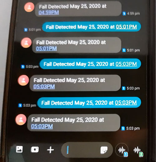
Testing the IoT Fall Detector
Once your code and hardware are ready, upload the code. To test the project, take the MPU6050 in your hands and pretend to be walking slowly and then suddenly trip on a ledge as shown in the video given below. If the magnitude exceeds the threshold value, the device will activate the fall detection alarm and send a message to the registered number.
The complete code and working video are given at the end of the project.
#include <Wire.h>
#include <ESP8266WiFi.h>
const int MPU_addr=0x68; // I2C address of the MPU-6050
int16_t AcX,AcY,AcZ,Tmp,GyX,GyY,GyZ;
float ax=0, ay=0, az=0, gx=0, gy=0, gz=0;
boolean fall = false; //stores if a fall has occurred
boolean trigger1=false; //stores if first trigger (lower threshold) has occurred
boolean trigger2=false; //stores if second trigger (upper threshold) has occurred
boolean trigger3=false; //stores if third trigger (orientation change) has occurred
byte trigger1count=0; //stores the counts past since trigger 1 was set true
byte trigger2count=0; //stores the counts past since trigger 2 was set true
byte trigger3count=0; //stores the counts past since trigger 3 was set true
int angleChange=0;
// WiFi network info.
const char *ssid = "Galaxy-M20"; // Enter your WiFi Name
const char *pass = "ac312124"; // Enter your WiFi Password
void send_event(const char *event);
const char *host = "maker.ifttt.com";
const char *privateKey = "hUAAAz0AVvc6-NW1UmqWXXv6VQWmpiGFxx3sV5rnaM9";
void setup(){
Serial.begin(115200);
Wire.begin();
Wire.beginTransmission(MPU_addr);
Wire.write(0x6B); // PWR_MGMT_1 register
Wire.write(0); // set to zero (wakes up the MPU-6050)
Wire.endTransmission(true);
Serial.println("Wrote to IMU");
Serial.println("Connecting to ");
Serial.println(ssid);
WiFi.begin(ssid, pass);
while (WiFi.status() != WL_CONNECTED)
{
delay(500);
Serial.print("."); // print ... till not connected
}
Serial.println("");
Serial.println("WiFi connected");
}
void loop(){
mpu_read();
ax = (AcX-2050)/16384.00;
ay = (AcY-77)/16384.00;
az = (AcZ-1947)/16384.00;
gx = (GyX+270)/131.07;
gy = (GyY-351)/131.07;
gz = (GyZ+136)/131.07;
// calculating Amplitute vactor for 3 axis
float Raw_Amp = pow(pow(ax,2)+pow(ay,2)+pow(az,2),0.5);
int Amp = Raw_Amp * 10; // Mulitiplied by 10 bcz values are between 0 to 1
Serial.println(Amp);
if (Amp<=2 && trigger2==false){ //if AM breaks lower threshold (0.4g)
trigger1=true;
Serial.println("TRIGGER 1 ACTIVATED");
}
if (trigger1==true){
trigger1count++;
if (Amp>=12){ //if AM breaks upper threshold (3g)
trigger2=true;
Serial.println("TRIGGER 2 ACTIVATED");
trigger1=false; trigger1count=0;
}
}
if (trigger2==true){
trigger2count++;
angleChange = pow(pow(gx,2)+pow(gy,2)+pow(gz,2),0.5); Serial.println(angleChange);
if (angleChange>=30 && angleChange<=400){ //if orientation changes by between 80-100 degrees
trigger3=true; trigger2=false; trigger2count=0;
Serial.println(angleChange);
Serial.println("TRIGGER 3 ACTIVATED");
}
}
if (trigger3==true){
trigger3count++;
if (trigger3count>=10){
angleChange = pow(pow(gx,2)+pow(gy,2)+pow(gz,2),0.5);
//delay(10);
Serial.println(angleChange);
if ((angleChange>=0) && (angleChange<=10)){ //if orientation changes remains between 0-10 degrees
fall=true; trigger3=false; trigger3count=0;
Serial.println(angleChange);
}
else{ //user regained normal orientation
trigger3=false; trigger3count=0;
Serial.println("TRIGGER 3 DEACTIVATED");
}
}
}
if (fall==true){ //in event of a fall detection
Serial.println("FALL DETECTED");
send_event("fall_detect");
fall=false;
}
if (trigger2count>=6){ //allow 0.5s for orientation change
trigger2=false; trigger2count=0;
Serial.println("TRIGGER 2 DECACTIVATED");
}
if (trigger1count>=6){ //allow 0.5s for AM to break upper threshold
trigger1=false; trigger1count=0;
Serial.println("TRIGGER 1 DECACTIVATED");
}
delay(100);
}
void mpu_read(){
Wire.beginTransmission(MPU_addr);
Wire.write(0x3B); // starting with register 0x3B (ACCEL_XOUT_H)
Wire.endTransmission(false);
Wire.requestFrom(MPU_addr,14,true); // request a total of 14 registers
AcX=Wire.read()<<8|Wire.read(); // 0x3B (ACCEL_XOUT_H) & 0x3C (ACCEL_XOUT_L)
AcY=Wire.read()<<8|Wire.read(); // 0x3D (ACCEL_YOUT_H) & 0x3E (ACCEL_YOUT_L)
AcZ=Wire.read()<<8|Wire.read(); // 0x3F (ACCEL_ZOUT_H) & 0x40 (ACCEL_ZOUT_L)
Tmp=Wire.read()<<8|Wire.read(); // 0x41 (TEMP_OUT_H) & 0x42 (TEMP_OUT_L)
GyX=Wire.read()<<8|Wire.read(); // 0x43 (GYRO_XOUT_H) & 0x44 (GYRO_XOUT_L)
GyY=Wire.read()<<8|Wire.read(); // 0x45 (GYRO_YOUT_H) & 0x46 (GYRO_YOUT_L)
GyZ=Wire.read()<<8|Wire.read(); // 0x47 (GYRO_ZOUT_H) & 0x48 (GYRO_ZOUT_L)
}
void send_event(const char *event)
{
Serial.print("Connecting to ");
Serial.println(host);
// Use WiFiClient class to create TCP connections
WiFiClient client;
const int httpPort = 80;
if (!client.connect(host, httpPort)) {
Serial.println("Connection failed");
return;
}
// We now create a URI for the request
String url = "/trigger/";
url += event;
url += "/with/key/";
url += privateKey;
Serial.print("Requesting URL: ");
Serial.println(url);
// This will send the request to the server
client.print(String("GET ") + url + " HTTP/1.1\r\n" +
"Host: " + host + "\r\n" +
"Connection: close\r\n\r\n");
while(client.connected())
{
if(client.available())
{
String line = client.readStringUntil('\r');
Serial.print(line);
} else {
// No data yet, wait a bit
delay(50);
};
}
Serial.println();
Serial.println("closing connection");
client.stop();
}


