


LEDs are used in almost every decorative lightings, but most of them only produce a single color. So to create a beautiful light pattern, multiple colors LED strips are used, which are, not only consumes more power but also hard to manage. Today we are using the new generation LED- NeoPixel, which can produce 16.8 million colors. NeoPixels are programmable, and with the right programming, it can create many beautiful lighting patterns. Here a NodeMCU and Blynk app will be used to control the color and brightness of NeoPixel LED strip over the internet. Blynk is a smartphone application, using which we can control any IoT based Application through our smartphone.
Components Required
- WS2812b LED Strip- 1 metre
- 5V,2 AMP Power supply
- ESP8266 NodeMCU
- LED Strip connectors
WS2812 NeoPixel LED Strip Working
![]()
WS2812 LED strips are addressable and programmable Flexible LED strips which are very useful in creating the custom lighting effects. These LED Strips are powered by a 5050 RGB LED with a WS2812 LED driver inbuilt within it. Each LED consumes 60mA current and can be powered from a 5V DC supply. It has a single input data pin which can be fed from the digital pins of Microcontrollers.
Features:
- Individually addressable RGB LEDs
- 16.8 million colors per pixel
- Single-wire digital control
- Operating Voltage: 5V DC
- Current Requirement: 60mA per LED
- Flexible LED structure
- 5050 RGB LED with WS2812 driver
Connection diagram:
Circuit diagram for NeoPixel NodeMCU is given below:
![]()
Below image shows the setup for NeoPixel ESP8266
![]()
Blynk Application Setup for controlling NeoPixel
Blynk is an application that runs over Android and IOS devices to control any IoT based application using Smartphones. We previously used Blynk with NodeMCU and Raspberry Pi to control an LED and also build a weather station using the Blynk app. It allows you to create your Graphical user interface for IoT application. Here we will set up the Blynk application to control NeoPixel LED over Wi-Fi using NodeMCU ESP8266.
So first download and install the Blynk Application from Google Play store (IOS users can download from App Store) and sign-up using your Email id and Password.
Creating a new Project:
After successful installation, open the application and click on “New Project”. Then it will pop up a new screen, where we need to set the parameters like Project name, Board and connection type. For this NeoPixel ESP8266 project select the device as NodeMCU and connection type as Wi-Fi and click on “Create”.
After the successful creation of the Project, we will get an Authenticate ID on registered mail. Save the Authenticate ID for future reference.
![]()
Creating the GUI:
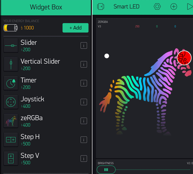
Open the project in Blynk, click on the “+” sign to add the widgets to control the NeoPixel. In our case, we need an RGB Color Picker which is listed as “zeRGBa” and a slider that will be used for brightness control of the LED strip.
Setting the Parameter in Widgets:
After dragging the widgets, they now set their parameters which are used to send the color and brightness values to NodeMCU.
Click on ZeRGBa, to go into ZeRGBa setting and set the Output option to “Merge” and set the pin to “V3” which is shown in the image below. Similarly, in Slider settings, set the output pin to “V2.”
![]()
Programming NodeMCU to control NeoPixel using Wi-Fi
After successful completion of the Blynk application setup, now upload the code in NodeMCU using Arduino IDE.
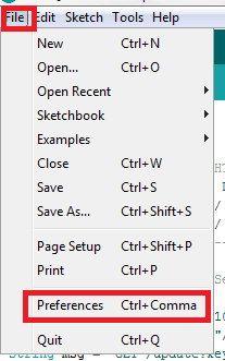
To program NodeMCU with Arduino IDE go to File–>Perferences–>Settings.
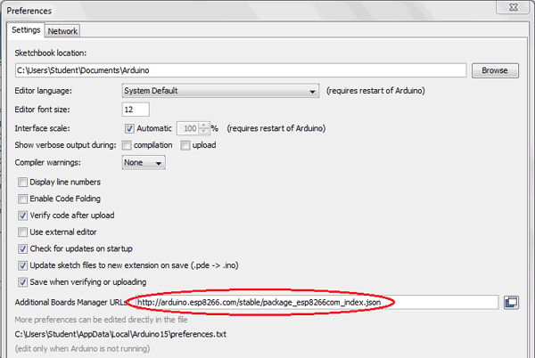
Enter https:// arduino.esp8266.com/stable/package_esp8266com_index.json into the ‘Additional Board Manager URL’ field and click ‘Ok’.
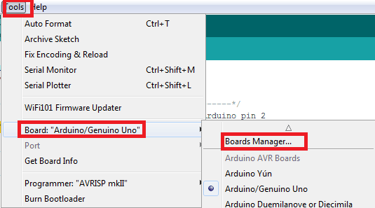
Now go to Tools > Board > Boards Manager.
In Boards Manager window, Type esp in the search box, esp8266 will be listed there below. Now select the latest version of the board and click on install.
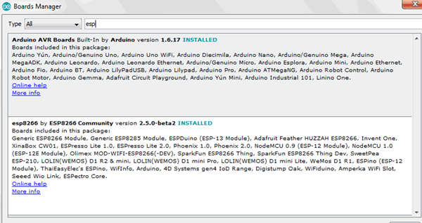
After installation is complete, go to Tools >Board >and select NodeMCU 1.0(ESP-12E Module). Now you can program NodeMCU with Arduino IDE.
Complete code along with the video is given at the end. The step-wise explanation of the code is shown below.
First of all, including all the required libraries. Open Arduino IDE, then go to the tab Sketch and click on the option Include Library-> Manage Libraries. Then search for Blynk in the search box and then download and install the Blynk package for ESP8266.
For including FastLED.h library, download the library from here and include it using Include ZIP Library option.
#define BLYNK_PRINT Serial
#include <BlynkSimpleEsp8266.h>
#define FASTLED_ESP8266_RAW_PIN_ORDER
#include "FastLED.h"
Now, define all the parameters like the number of LEDs used, LED type and color order in the code. Also, define the data PIN D1 where the data input pin of RGB LED is connected. Then, define your Wi-Fi user name and password in ssid[] and pass[] an array. Inside auth[] array, write the Blynk authenticate ID which we saved earlier.
#define NUM_LEDS1 60
#define LED_TYPE    WS2812
#define COLOR_ORDER GRB
CRGB leds1[NUM_LEDS1];
char auth[] = "XXXXaL9U92cXXXXXXXXXXXX";
char ssid[] = "admin";
char pass[] = "12345678";
#define PIN1 D1
Inside setup() function, initialize the serial communication using Serial.begin and connect to the Blynk cloud using Blynk.begin. Also, set the LED type and number of LEDs using FastLED.addLeds.
void setup()
{
  Serial.begin(9600);
  Blynk.begin(auth, ssid, pass);
  FastLED.addLeds<LED_TYPE, PIN1, COLOR_ORDER>(leds1, NUM_LEDS1).setCorrection( TypicalLEDStrip );
}
Inside infinite loop (), we have used Blynk.run () to check the incoming commands from Blynk GUI and executes the operations accordingly.
void loop()
{
  Blynk.run();
}
Here BLYNK_WRITE function is written to check for incoming data at V3 and V2 Virtual terminal, then assign them in three different variables. The variable r, g, b here represents the value of Red, Green and Blue code of the selected color. Similarly, here data is used for storing the brightness value of the LED. Then these values are sent to the function static1 which is used for driving the LED strip.
BLYNK_WRITE (V3)
{
  r = param[0].asInt();
  g = param[1].asInt();
  b = param[2].asInt();
  static1(r, g, b,data);
}

BLYNK_WRITE(V2)
{
data = param.asInt();
static1(r, g, b,data);
}
Static1 () function is used to drive the LED strip and to control the brightness of the LED strip. And FastLED.setBrightness is used to set the brightness of the LED. Similarly FastLED.show function is used for driving the LED as per the required color.
void static1(int r, int g, int b,int brightness)
{
  FastLED.setBrightness(brightness);
  for (int i = 0; i < NUM_LEDS1; i++ )
  {
    leds1[i] = CRGB(r, g, b);
  }
  FastLED.show();
}
After uploading the complete code into NodeMCU using Arduino IDE, you can control the color and brightness of NeoPixels LED strips from the Blynk mobile app, as shown in the picture below.
![]()
![]()
Find below the complete code and working video for this ESP8266 NeoPixel Wi-Fi control.
#define BLYNK_PRINT Serial
#include <BlynkSimpleEsp8266.h>
#define FASTLED_ESP8266_RAW_PIN_ORDER
#include "FastLED.h"
#define NUM_LEDS1 60
#define LED_TYPE WS2812
#define COLOR_ORDER GRB
CRGB leds1[NUM_LEDS1];
char auth[] = "fu0oXXXX9U92cXXXXXXX";
char ssid[] = "admin";
char pass[] = "12345678";
#define PIN1 D1
int data=255;
int r,g,b;
void setup()
{
Serial.begin(9600);
Blynk.begin(auth, ssid, pass);
FastLED.addLeds<LED_TYPE, PIN1, COLOR_ORDER>(leds1, NUM_LEDS1).setCorrection( TypicalLEDStrip );
}
BLYNK_WRITE(V3)
{
r = param[0].asInt();
g = param[1].asInt();
b = param[2].asInt();
static1(r, g, b,data);
}
void loop()
{
Blynk.run();
}
BLYNK_WRITE(V2)
{
data = param.asInt();
static1(r, g, b,data);
}
void static1(int r, int g, int b,int brightness)
{
FastLED.setBrightness(brightness);
for (int i = 0; i < NUM_LEDS1; i++ )
{
leds1[i] = CRGB(r, g, b);
}
FastLED.show();
}


