


Here we are building an IoT water level monitoring system using a float level sensor and NodeMCU ESP8266 to monitor the level of water and publish it on a web-server. This system will turn on the water pump automatically if the water level goes low and turn off the water pump when the water level reaches to full capacity. The user can also manually override the control of the pump from the webserver. If you are new to ESP8266, then learn creating the ESP8266 based webserver before proceeding further. Also, check other ESP8266 based IoT Projects here.
Float Sensor
A Float sensor or Float Switch Sensor is a device that is used to sense the level of liquid within the tank. The main purpose of this Water Float Switch is to open or close the circuit as the level of a liquid rises or falls. Most of the float switches are in the “normally closed” position. That means the two wires coming from the top of the switch complete a circuit when the float is at its bottom position (for eg, when a tank is empty). A float switch uses a magnetic reed switch to open or close the circuit. The reed is enclosed in a glass tube, which is cemented into a plastic or stainless steel stem with epoxy.
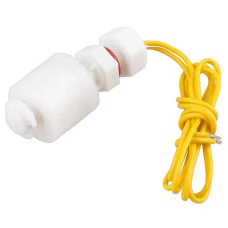
This Magnetic Float Sensor encases a sealed magnet, which moves up and down along the length of the stem as the fluid level rise or fall. When the magnet comes close to the two contacts, it allow the current to pass through and when the magnet moves away, the contacts separate and demagnetize, hence breaks the circuit. A properly used float switch can deliver millions of ON/OFF cycles, for years of operation. Failures are normally due to overloading, caused by frequently spiking voltage. The float switch can be used to actuate a pump, an alarm, an indicator, or other devices. Since the current that the switch can carry is much little (0.5A), a relay must be used when it is connected to a load. The switch can be easily converted from normally open to normally close by inverting the float.
Programing NodeMCU with Arduino IDE
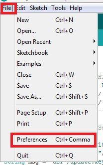
To program NodeMCU with Arduino IDE go to File–>Perferences–>Settings.
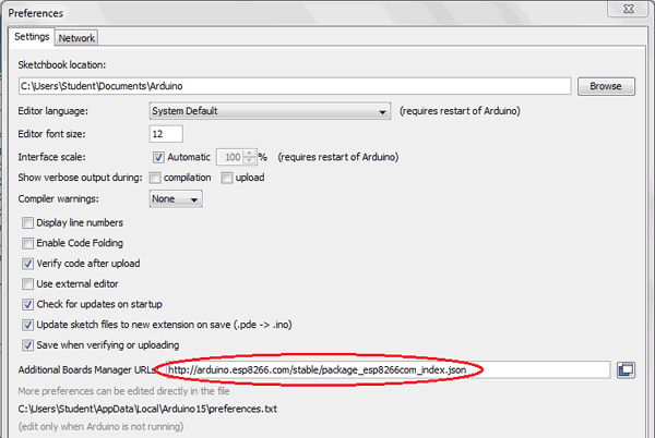
Enter http:// arduino.esp8266.com/stable/package_esp8266com_index.json into ‘Additional Board Manager URL’ field and click ‘Ok’.
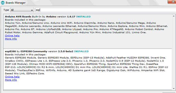
Now go to Tools > Board > Boards Manager.
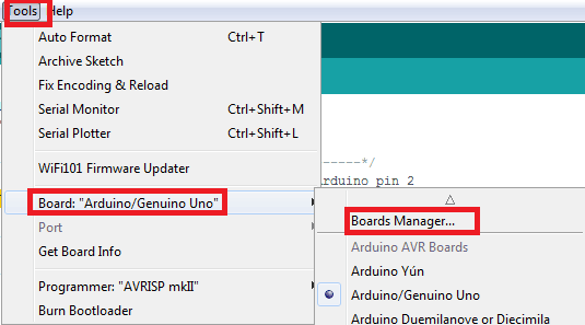
In Boards Manager window, Type esp in the search box, esp8266 will be listed there below. Now select latest version of board and click on install.
After installation is complete, go to Tools >Board >and select NodeMCU 1.0(ESP-12E Module). Now you can program NodeMCU with Arduino IDE.
Required Components
- ESP8266 NodeMCU
- Float Sensor
- Relay module
- LED
- Connecting wires
- Arduino IDE
Circuit Diagram
Below is the circuit diagram for the Automatic Water Level Monitoring System:
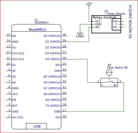
Here a water level float switch is used to determine the level of water inside the tank. The float switch consists of two wires. One wire of the float switch is connected to the D4 pin (GPIO2) of the NodeMCU, and the other wire is connected to the ground. The value of the float sensor is read by the NodeMCU. If the value is “HIGH” means the tank is full and if the value is “LOW” the tank is empty. A relay module is connected to the D1pin (GPIO5), which is connected to the switch of the water pump. When the water level is low the switch is turned ON automatically, and when the water level is high the switch is turned OFF.
Code Explanation
Complete program for this Wireless Water Level Monitoring System is given at the end of this article. Copy and upload the program into NodeMCU and open the serial monitor. In the serial monitor, you will be able to see some information like whether the WiFi is connected or not. If it is connected you will get the local IP address, here it is 192.168.1.23( This may be different for you). Note down the one that displayed on your serial monitor.
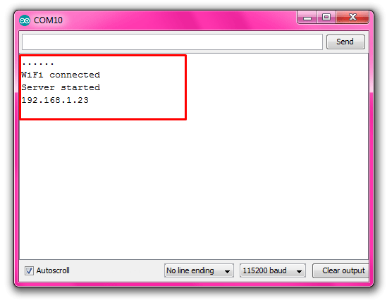
Note: If the serial monitor is blank and not displaying anything then press the RESET button on the NodeMCU board
Now after uploading the code open a webpage on your computer (just open a page in Google Chrome, Firefox or any browser) and type the IP address that we have collected from the serial monitor in the address bar and click ENTER on your keyboard. Now you will be able to see the water level, and you can also control the pump ON/OFF from the webserver. The webpage should look like below:
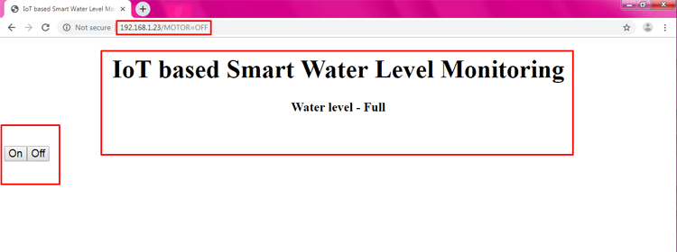
You can customize the appearance of the webpage by changing the HTML part in the below-given code. Also, check the demonstration video given below.
#include <ESP8266WiFi.h>
int FloatSensor = 2; //D4 pin of NodeMCU
int buttonState ; //reads pushbutton status
const char* ssid = "Onlilo_SP"; //ssid of your wifi
const char* password = "@rduin0un0"; //password of your wifi
String level;
int relay = 5; // D1 pin of NodeMCU
WiFiServer server(80);
void setup()
{
Serial.begin(115200);
Serial.println();
Serial.print("Connecting to ");
Serial.println(ssid);
WiFi.begin(ssid, password); //connecting to wifi
while (WiFi.status() != WL_CONNECTED)// while wifi not connected
{
delay(500);
Serial.print("."); //print "...."
}
Serial.println("");
Serial.println("WiFi connected");
server.begin();
Serial.println("Server started");
Serial.println(WiFi.localIP()); // Print the IP address
pinMode(FloatSensor, INPUT_PULLUP); //Arduino Internal Resistor 10K
pinMode(relay, OUTPUT); // set relay pin as output
digitalWrite(relay, LOW);
delay(4000);
}
void loop()
{
int value ;
buttonState = digitalRead(FloatSensor); // read the value of float sensor
if (buttonState == HIGH) // if the value is HIGH
{ // the level is high
Serial.println( "WATER LEVEL - HIGH");
level = "Full";
digitalWrite(relay, LOW); // turn OFF the relay
//value = LOW;
}
else
{
Serial.println( "WATER LEVEL - LOW" ); // if the value is LOW
level = "Empty"; // the level is low
digitalWrite(relay, HIGH); // turn ON the relay
//value = HIGH;
}
WiFiClient client = server.available(); // Check if a client has connected
if (!client)
{
return;
}
String request = client.readStringUntil('\r');
Serial.println(request);
client.flush();
// Match the request
if (request.indexOf("/MOTOR=ON") != -1)
{
digitalWrite(relay, HIGH); // if request is ON, turn ON the relay.
value = HIGH;
}
if (request.indexOf("/MOTOR=OFF") != -1)
{
digitalWrite(relay, LOW); // if request is OFF, turn OFF the relay.
value = LOW;
}
delay(100);
// Prepare the response
String s = "HTTP/1.1 200 OK\r\nContent-Type: text/html\r\n\r\n <!DOCTYPE html> <html> <head> <title>IoT based Smart Water Level Monitoring</title> <style>";
s += "a:link {background-color: YELLOW;text-decoration: none;}";
s += "table, th, td </style> </head> <body> <h1 style=";
s += "font-size:300%;";
s += " ALIGN=CENTER> IoT based Smart Water Level Monitoring</h1>";
s += "<p ALIGN=CENTER style=""font-size:150%>";
s += "<b>Water level - </b><b>";
s += level;
s += "</b></p>";
s += "<br><br>";
s += "<a href=\"/MOTOR=ON\"\"><button><ALIGN=CENTER style=""font-size:150%>On </button></a>";
s += "<a href=\"/MOTOR=OFF\"\"><button><ALIGN=CENTER style=""font-size:150%>Off </button></a><br />";
s += "</body> </html> \n";
client.print(s); // all the values are send to the webpage
delay(100);
}


