


Robotic Arms have been used by industries to perform complicated and tedious jobs ever since its introduction in 1962. From assembly lines to paint shops these robotic arms are used extensively in Automotive Manufacturing Industries. Recently with the advancement of technology and advent of Internet of thins (IoT), Robotic arms have also started to plunge in the Medical Applications allowing doctors to perform surgeries remotely by controlling the robotic arm wirelessly. In this project we will build an IoT based Wireless Robotic Arm using NodeMCU.
The 3D printed robotic arm position can be controlled from any Internet enabled smart phone by using an application called Blynk which is available for free for both Android and IOS users. We have previously used Blynk with NodeMCU and with Raspberry Pi to control GPIO connected appliances.
3D printing your Robotic ARM
As mentioned earlier the robotic arm used in this project is 3D printed, if you do not have a printer you can used any Robotic Arm or build a crude one using cardboards. The 3D printed Robotic Arm design is taken from this link on Thingiverse. This link also has complete detailed video showing the procedure of making and assembling this 3D printed Robotic Arm.
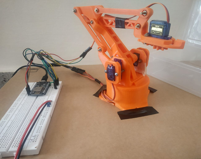
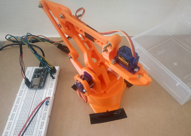
This is the image of my 3D printed Robotic Arm after assembling with 4 Towerpro SG90 Servo Motors. I have simply used nuts and bolts to put to-gather the complete robotic arm. Again all information is available at thingiverse.
Setting up Blynk Application for Robotic Arm
Blynk is an IoT platform that allows us to quickly build projects for controlling and monitoring the data using Android and iOS devices. We can create project dashboard and add widgets like button, display, sliders, etc. for controlling microcontrollers and other peripherals. Using these widgets we can control the devices and can monitor the sensor data on the phone screen. Follow the below steps to install Blynk and create dashboard for robotic arm control.
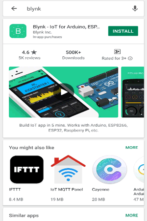
1. In your mobile phone Install the blynk application from the Google Play Store.
2. Next sign up for the Blynk application using the email id.
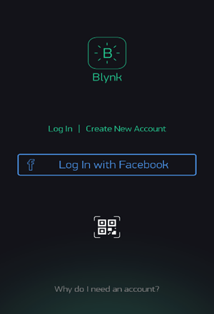
3. After signing up login the Blynk application.
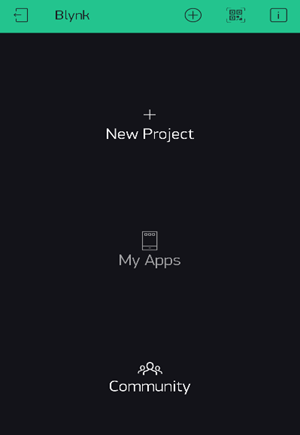
4. After login, click on New Project.
5. Next Project Name is given as per required and Board we use is “NodeMCU” is selected and connection type is given as “WiFi”
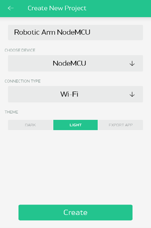
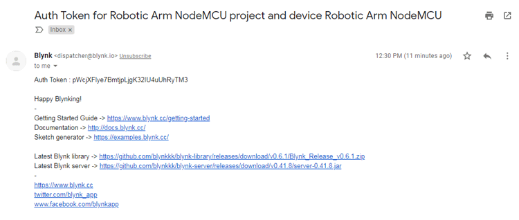
6. After that click Create. And an Auth Token code is sent to your mail ID.
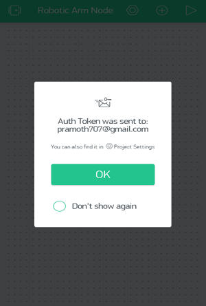
7. Copy the Auth Token Code sent to your mail ID we will use it in our NodeMCU coding.
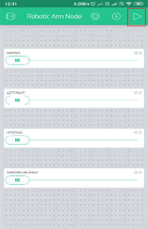
8. Next we have to create our own application for our Robotic ARM Control by adding the widgets in the widgets box. As we have four servo motor control, I have added four sliders.
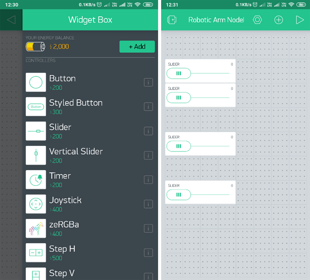
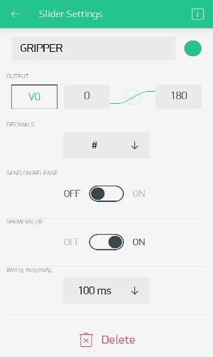
9. After Adding the Sliders. You can change each sliders name and Slider value and then the Slider settings.
Here I have set
Slider 1 as GRIPPER with settings as OUTPUT V0 from 0 to 180.
Slider 2 as LEFT/RIGHT with settings as OUTPUT V1 from 0 to 180.
Slider 3 as UP/DOWN with settings as OUTPUT V2 from 0 to 90.
Slider 4 as FORWARD/REVERSE with settings as OUTPUT V3 from 0 to 60.
For ALL Sliders I have turned OFF the SEND ON RELEASE. So that we can keep a Write Delay of 100ms between the values.
10. After Adding all the sliders with above settings, the application looks like this. After that you can run the application by clicking Play Button.
11. Now our application is ready. Next thing is to make the circuit connections and upload code to the NodeMCU. After that we can control our Robotic ARM using the Blynk Application.
Components Required
- NodeMCU ESP8266
- Servo Motors – 4
- Robotic ARM
- 5V 1A DC Power Adapter
- Breadboard
- Connecting Wires
Circuit Diagram
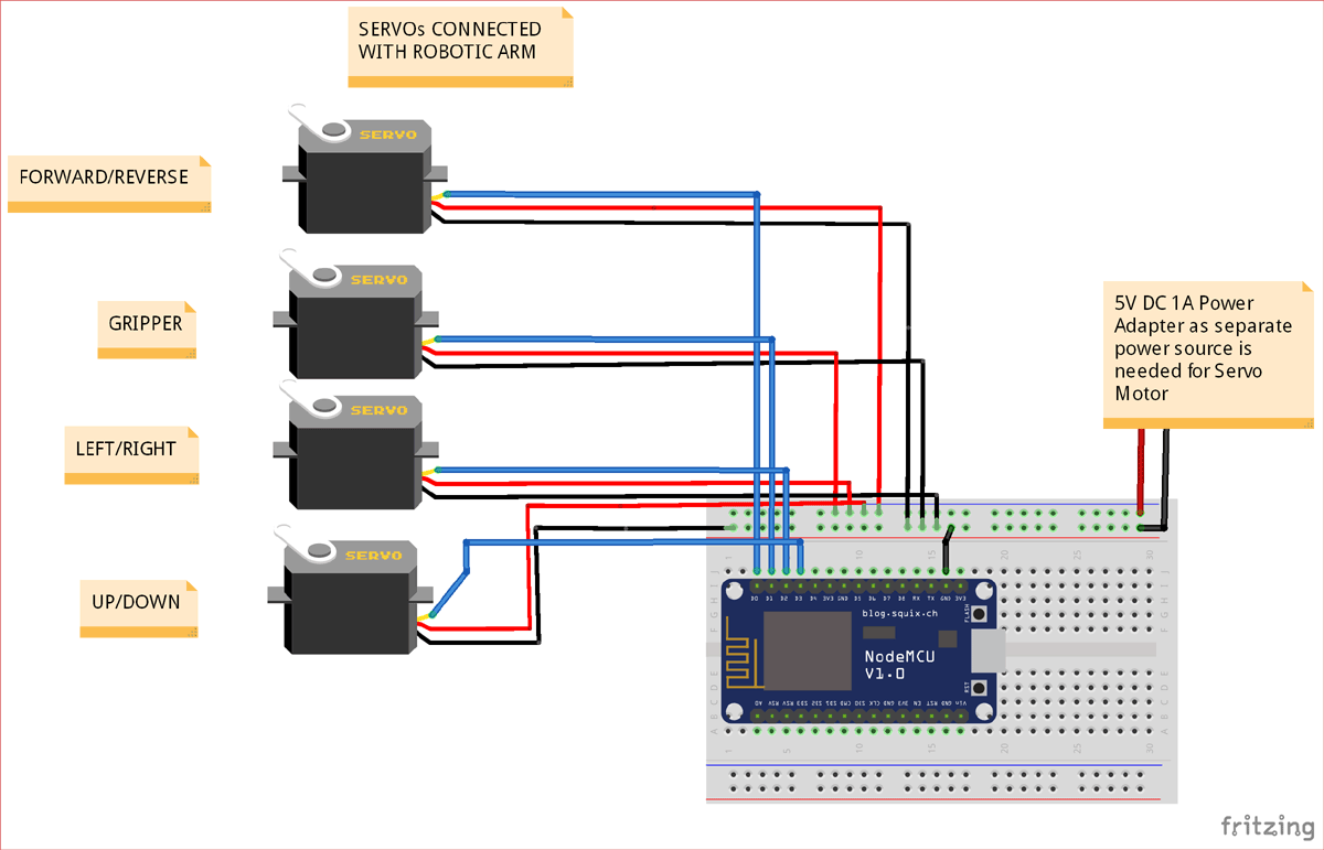
As shown above we will need a total of 4 servo motor to operate our robotic arm, since these motors do not consume much power they are being driven directly by the 5V dc supply from our 1A adapter. I have used the breadboard to make the above connections; once the connections are done my set-up looks something like this.
Circuit Connections:
|
NodeMCU |
SERVO MOTOR |
Power Adapter |
|
D0 |
Servo 1 Orange (PWM Pin) |
- |
|
D1 |
Servo 2 Orange (PWM Pin) |
- |
|
D2 |
Servo 3 Orange (PWM Pin) |
- |
|
D3 |
Servo 4 Orange (PWM Pin) |
- |
|
GND |
Servo 1,2,3,4 Brown (GND Pin) |
GND |
|
- |
Servo 1,2,3,4 Red (+5V Pin) |
+5V |
Working of IoT based Robotic Arm
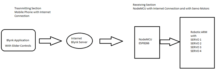
The working of the project is so simple, we are just controlling the Robotic Arm’s four servo motor from an application using the internet. The NodeMCU has an inbuilt ESP8266 Wi-Fi Module so that we can connect the NodeMCU to the internet. Next using the Blynk application in the mobile we have created an application to send values via internet to control the PWM values for the four-servo motor that are connected with the NodeMCU.
In the Blynk application four sliders are used. The Servo motor is controlled according to the slider movement by the user.
Setting Up Blynk & NodeMCU (ESP8266) Library for Arduino IDE
The coding for this IoT Robotic Arm project is so simple and complete code with working video is given at the end of the article. First, we need the Blynk library for Arduino IDE. To download and setup manually follow these links below.
1. Download the Blynk library from the GitHub link here.
2. After that to install the Blynk Library for Arduino follow this link here.
So, after setting up the Blynk library for Arduino IDE. Second, we need the NodeMCU library for Arduino IDE.
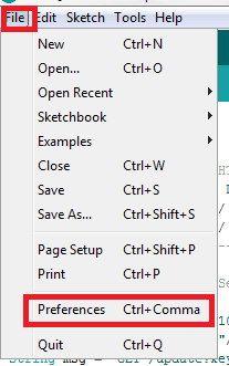
To program NodeMCU with Arduino IDE go to File–>Perferences–>Settings.
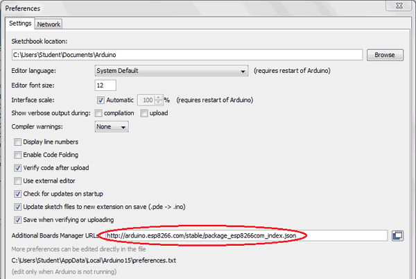
Enter http:// arduino.esp8266.com/stable/package_esp8266com_index.json into ‘Additional Board Manager URL’ field and click ‘Ok’.
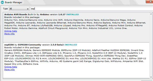
Now go to Tools > Board > Boards Manager.
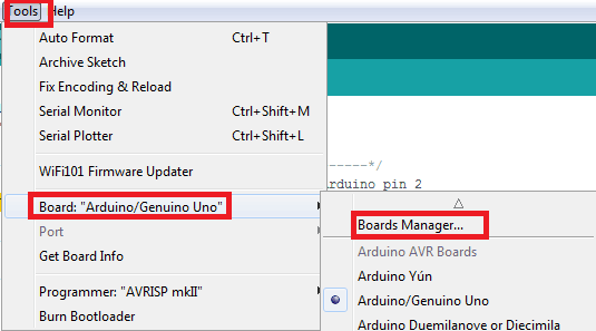
In Boards Manager window, Type esp in the search box, esp8266 will be listed there below. Now select latest version of board and click on install.
After installation is complete, go to Tools >Board >and select NodeMCU 1.0(ESP-12E Module). Now you can program NodeMCU with Arduino IDE.
Coding Explanation
After installing the libraries for Blynk and NodeMCU (ESP8266). The complete code is given at the end of this tutorial. Code is uploaded to the NodeMCU via microUSB cable. Now let’s see about coding for this project in detail.
1. First the necessary libraries are included
For ESP8266 (NodeMCU):
#include <ESP8266WiFi.h>
For using Blynk :
#include <BlynkSimpleEsp8266.h>
For using Servo Motor:
#include <Servo.h>
2. Next Blynk Auth Code received via mail and the Wifi Username (ssid) and Password are entered according to the below given code.
char auth[] = "pWcjXFlye7BmtjpLjgK32IU4uUhRyTM3";
             char ssid[] = "";
             char pass[] = "";
3. We are using Four Servo motors with the robotic arm in this project so we have created four objects with class servo.
Servo servo;
Servo servo1;
Servo servo2;
Servo servo3;
4. Next in the void setup() function we initialize the device by providing Wi-Fi username and password with Auth Token and begin Serial communication.
Serial.begin(9600);
Blynk.begin(auth, ssid, pass);
Also initialize the servo motor PWM pins connected with NodeMCU, using the pins D0,D1,D2,D3.
           servo.attach(D0);
             servo1.attach(D1);
             servo2.attach(D2);
             servo3.attach(D3);
5. Then control the servo motor position according to the value received from the Blynk app. Here the virtual pins V0, V1, V2, V3 are used for taking input values from Blynk app and also write the PWM value to the corresponding servo motor.
BLYNK_WRITE(V3)
{
  servo.write(param.asInt());
}

BLYNK_WRITE(V0)
{
  servo1.write(param.asInt());
}

BLYNK_WRITE(V1)
{
  servo2.write(param.asInt());
}

BLYNK_WRITE(V2)
{
  servo3.write(param.asInt());
}
6. To run the Blynk function in loop
void loop()
{
  Blynk.run();
}
So this is how a IoT Robotic Arm can be built and controlled remotely using the Blynk App.
Check the complete code and video given below.
#define BLYNK_PRINT Serial
#include <ESP8266WiFi.h>
#include <BlynkSimpleEsp8266.h>
#include <Servo.h>
// You should get Auth Token in the Blynk App.
// Go to the Project Settings (nut icon).
char auth[] = " "; //Paste your Auth Token Here
// Your WiFi credentials.
// Set password to "" for open networks.
char ssid[] = " "; //Enter your Wifi User Name
char pass[] = " "; //Enter your Wifi Password
Servo servo;
Servo servo1;
Servo servo2;
Servo servo3;
BLYNK_WRITE(V3)
{
servo.write(param.asInt());
}
BLYNK_WRITE(V0)
{
servo1.write(param.asInt());
}
BLYNK_WRITE(V1)
{
servo2.write(param.asInt());
}
BLYNK_WRITE(V2)
{
servo3.write(param.asInt());
}
void setup()
{
// Debug console
Serial.begin(9600);
Blynk.begin(auth, ssid, pass);
// You can also specify server:
//Blynk.begin(auth, ssid, pass, "blynk-cloud.com", 80);
//Blynk.begin(auth, ssid, pass, IPAddress(192,168,1,100), 8080);
servo.attach(D0);
servo1.attach(D1);
servo2.attach(D2);
servo3.attach(D3);
}
void loop()
{
Blynk.run();
}


