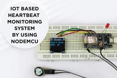
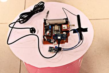
A definitive and comprehensive vehicle accident and rash driving identification and alert system using NodeMCU. Unlike other projects across the internet, it has a fully functional and independent circuitry. It combines the features of Invensense’s MPU6050, Ublox Neo-6M GPS module with NodeMCU to a great effect. MPU6050 is a combination of the accelerometer and the gyroscope, with both the modules help the other with the data to overcome the shortcomings. Accelerometer records the acceleration across 3 axes, whereas the gyroscope records the rotational velocity across the axis. The GPS module encodes the data in the form NMEA format, which can be used to carve out the exact location of the misfortune. In addition to that, a mail is also sent to the registered mail id through an API call embedded with the google link. A service called IFTTT connects different services to help us send the mail. The email conveys the message and also sends the location of the accident to the user. You can also check-out the IoT based Vehicle tracking project if you want to track the location of the vehicle in real-time.
Materials Required
- NodeMCU
- MPU6050
- Ublox-Neo 6M GPS Module
- 16*2 LCD Display
- Bread Board
- Jumper Wires
MPU6050
The MPU-6050 devices use both the accelerometer and gyroscope values across 3 axes to use it on the Digital Motion Processor Circuit. It has registers present in it to configure the gyro scale with ±250, ±500, ±1000, and ±2000 °/sec (dps), and also presents us with an accelerometer scale of ±2g, ±4g, ±8g, and ±16g. Selecting the range for the component selects its precision. It also includes a built-in temperature sensor.
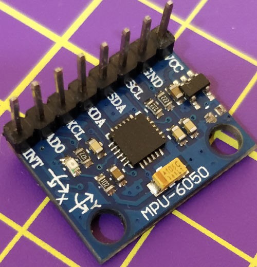
When a change in position of the sensor is detected, mechanical systems present inside the sensor produce voltage, which is subsequently connected to a 16bit ADC and is transferred to a FIFO buffer. The data is the buffer is communicated to the MCU through the I2C communication protocol.
Neo 6M GPS Module
The NEO-6M module comes with a dimension of 16 x 12.2 x 2.4 mm package. It has 6 Ublox positioning engines offering unmatched performance. It is a good performance GPS receiver with a compact architecture, low power consumption, and reliable memory options. It is ideal for battery-operated mobile devices considering its architecture and power demands. The Time-to-First-Fix is less than 1 second and it enables it to find the satellites almost instantly. The output is in the format of NMEA standards, which can be decoded to find the coordinates and Time of the location.

- Power supply: 2.8V to 5V
- Interface: RS232 TTL
- Built-in EEPROM and external antenna
- Default baud rate: 9600 bps
NodeMCU
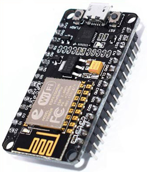
NodeMCU is configured to work on the Arduino IDE as an open-source firmware platform. There are also opensource prototyping board designs available. The firmware is scripted using Lua. It can act both as a standalone microcontroller and also as a node in an IoT ecosystem. The module used here is an ESP-12 based NodeMCU module.
Email Alert and IFTTT
IFTTT is a free web-based service, that allows the users to create applets with simple conditional statements. It generally allows the user to create the applet using the if statement (If this happens, then do an action). The event is normally triggered by an API call. The API call contains the API key, hostname, port, event name, and the values to be passed. For this project, the user needs to create an applet that can send a mail to the owner of the vehicle with its GPS location attached. We have previously used IFTTT with Raspberry pi and also in many other home automation and IoT monitoring projects.
To create an applet, follow the procedure:
Step 1: Create an applet by launching webhooks.

Go to Documentation at the top right corner and copy the key at the top.

Step 2: Create an applet by clicking the ‘+’ icon and selecting webhooks and then select a ‘receive a web request’ and give the event name.

Then click ‘+’ symbol and select mail, click receive webmail.

Step 3: To include the google map link in the URL, go to the link attached here and copy the link highlighted in the picture attached below.
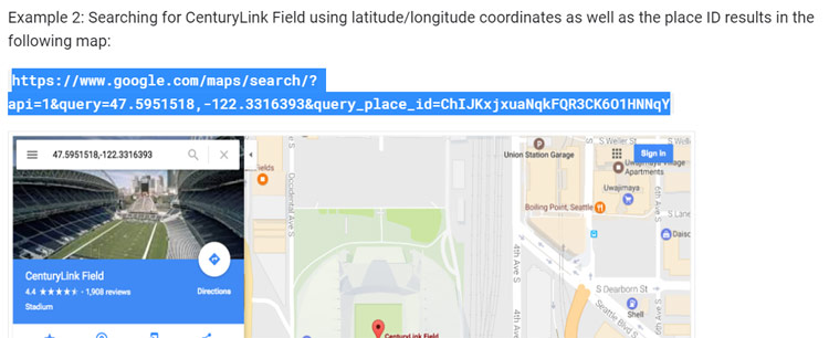
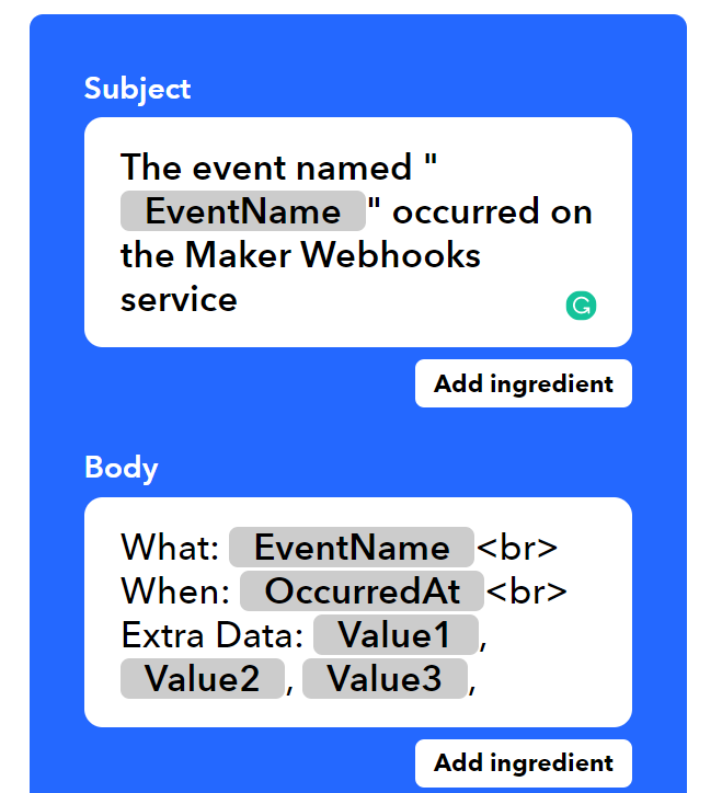
Then paste the link to the message body and replace the two floating-point numbers with ‘value1’ and ‘value2’. Then Create the applet.
Circuit Diagram and Connections
The complete circuit diagram for the Vehicle accident monitoring system is shown below:
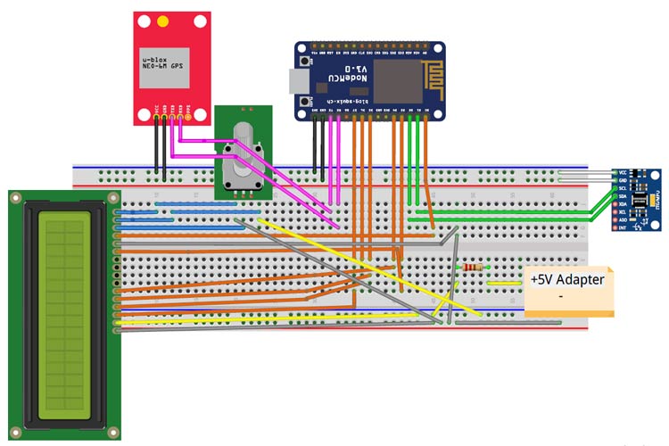
Connect each of the modules as shown in the circuit above.
MPU6050 and NodeMCU: The MPU uses I2C to communicate with the MPU6050. D1 and D2 pins are multiplexed with SCL and SDA respectively. MPU6050 is powered using 3.3V and Ground pins from the NodeMCU.
|
NodeMCU |
MPU6050 |
|
D1 |
SCL |
|
D2 |
SDA |
|
3.3V |
Vcc |
|
G |
Gnd |
Neo-6M GPS Module and NodeMCU: GPS Module uses asynchronous serial communication. The Tx of the NodeMCU is connected to the Rx pin of the module and the Rx pin is connected to the Tx pin of the module. The GPS module is powered using 3.3V and Ground pin of the NodeMCU.
|
NodeMCU |
6M GPS Module |
|
Tx |
Rx |
|
Rx |
Tx |
|
3.3V |
Vcc |
|
Gnd |
Gnd |
16x2 LCD Connection: Vdd and Vss are connected to the 5V DC adapter. Vo is connected from the potentiometer (10Kohm) output (center pin). The other two terminals of the pot are connected to 5V and Ground respectively. The remaining pins are to be connected as mentioned in the table below. A resistor of 220ohms is connected to limit the current consumption before connecting to the anode.
LCD pins
Vdd - 5V
Vss - Ground
Vo - potentiometer output
RS - D0 pin of NodeMCU
E - D3 pin of NodeMCU
D4 - D4 pin of NodeMCU
D5 - D5 pin of NodeMCU
D6 - D6 pin of NodeMCU
D7 - D7 pin of NodeMCU
A - 5V with 220ohm connected serially
K - Ground
IoT Vehicle Accident Monitoring - Code Explanation
Note: Disconnect the SCL, SDA, TX, and RX pins from the nodeMCU before dumping the code into it.
As the I2C works with a constant slave address, there is a need to address the slave with a particular address. The Serial clock (SCL) and Serial Data pins are also connected to D1 and D2 pins of the NodeMCU and it should be explicitly mentioned. The variable AccelScaleFactor is set the value of 16384, so as to scale the values as +-2g of acceleration. The values are calibrated to attain the zero value across the three axes.
const uint8_t MPU6050SlaveAddress = 0x68;
const uint8_t scl = D1;
const uint8_t sda = D2;
const uint16_t AccelScaleFactor = 16384;
Ax = (double)AccelX/AccelScaleFactor;
Ay = (double)AccelY/AccelScaleFactor;
Az = (double)AccelZ/AccelScaleFactor;
xvalue = Ax -1.03;
yvalue = Ay +0.06;
zvalue = Az -0.07;
The values obtained are divided by the scale factor to get the value within +-1. The difference between the previous and the current value of three axes are obtained in the variables dx, dy, and dz. When these values cross the threshold values, location, and mail functions are called.
if(((dx < MinValue) || (dx > MaxValue) || (dy < MinValue) || (dy > MaxValue)
|| (dz < MinValue) || (dz > MaxValue)) && (timer+millis()>12000))
Once the value crosses the threshold for an initial stipulated time, then the device connects to the available WiFi network using the SSID and password.
const char* ssid = "surya"; // Enter the name of your WiFi Network.
const char* password = "123456789";
// Enter the Password of your WiFi Network.
The GPS module is interfaced by including the TinyGPS++ library. The functions gps.location.lat() and gps.location.lng() are included in the library and is called to fetch the GPS coordinate values in floating point number.
latitude = gps.location.lat();
lat_str = String(latitude , 6);
longitude = gps.location.lng();
lng_str = String(longitude , 6);
To send the email using IFTTT, the parameters like Host, event name, and the API key are defined at the start.
#define HOSTIFTTT "maker.ifttt.com"
#define EVENTO "disturbance"
#define IFTTTKEY "p7zBBT6FHzN_7-6batwm3rg8v9T4gmrsjXSajuwaDJ1"
The board is connected to the host through HTTP and then the URL for API call is generated with parameters like the type of API call, event name, API key and the coordinates to be sent.
    if (client.connect(HOSTIFTTT,80)) {
    Serial.println("Connected");
    // build the HTTP request
    String toSend = "GET /trigger/";
    toSend += EVENTO;
    toSend += "/with/key/";
    toSend += IFTTTKEY;
    toSend += "?value1=";
    toSend += lat_str;
    toSend += "&value2=";
    toSend += lng_str;
    toSend += " HTTP/1.1\r\n";
    toSend += "Host: ";
    toSend += HOSTIFTTT;
    toSend += "\r\n";
    toSend += "Connection: close\r\n\r\n";
    client.print(toSend);
Working of Vehicle Accident Alert System
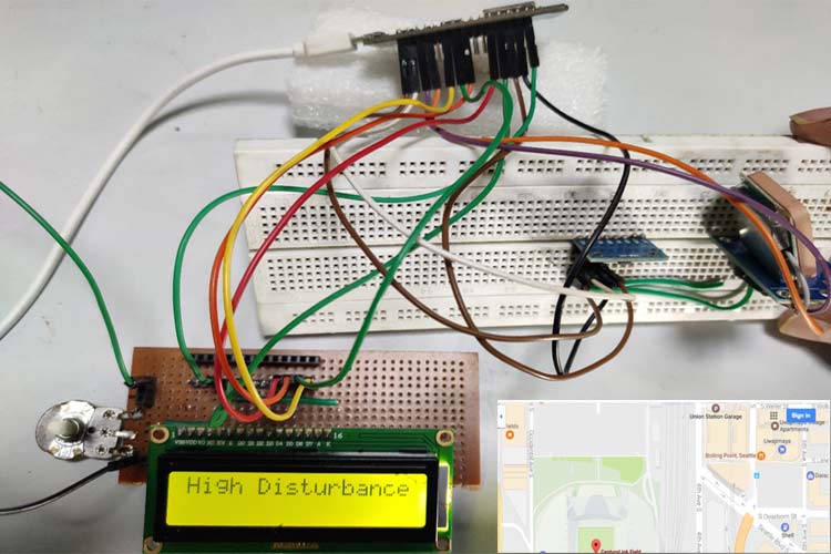
When there is a low disturbance (normal driving conditions), there is an indication in the LCD showing ‘Normal Driving’ and also the values across three phases.
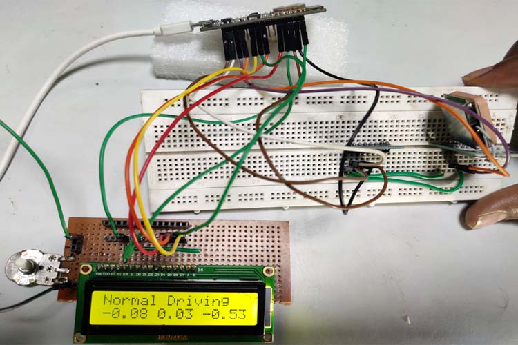
Low values in the display mean optimum driving conditions and the driver is safe. When the disturbance is simulated manually for a continuous period of 15-20 seconds, then there is a display showing ‘High Disturbance’ and an indication of the mail sent.
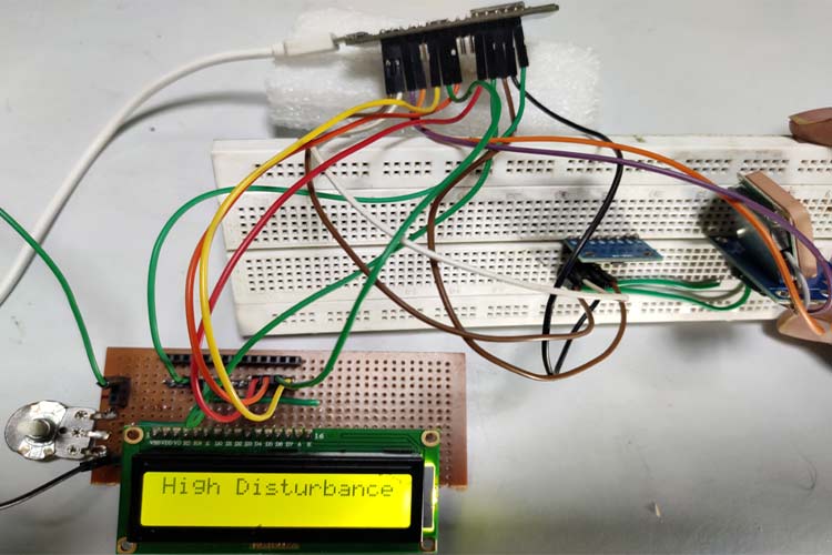
Complete code and demonstration video is given below.
#include <LiquidCrystal.h>
#include <TinyGPS++.h>
#include <Wire.h>
#include <ESP8266WiFi.h>
#define HOSTIFTTT "maker.ifttt.com"
#define EVENTO "disturbance"
#define IFTTTKEY "p7zBBT6FHzN_7-6batwm3rg8v9T4gmrsjXSajuwaDJ1"
TinyGPSPlus gps; // The TinyGPS++ object
// MPU6050 Slave Device Address
const uint8_t MPU6050SlaveAddress = 0x68;
// Select SDA and SCL pins for I2C communication
const uint8_t scl = D1;
const uint8_t sda = D2;
// sensitivity scale factor respective to full scale setting provided in datasheet
const uint16_t AccelScaleFactor = 16384;
// MPU6050 few configuration register addresses
const uint8_t MPU6050_REGISTER_SMPLRT_DIV = 0x19;
const uint8_t MPU6050_REGISTER_USER_CTRL = 0x6A;
const uint8_t MPU6050_REGISTER_PWR_MGMT_1 = 0x6B;
const uint8_t MPU6050_REGISTER_PWR_MGMT_2 = 0x6C;
const uint8_t MPU6050_REGISTER_CONFIG = 0x1A;
const uint8_t MPU6050_REGISTER_GYRO_CONFIG = 0x1B;
const uint8_t MPU6050_REGISTER_ACCEL_CONFIG = 0x1C;
const uint8_t MPU6050_REGISTER_FIFO_EN = 0x23;
const uint8_t MPU6050_REGISTER_INT_ENABLE = 0x38;
const uint8_t MPU6050_REGISTER_ACCEL_XOUT_H = 0x3B;
const uint8_t MPU6050_REGISTER_SIGNAL_PATH_RESET = 0x68;
int16_t AccelX, AccelY, AccelZ, Temperature, GyroX, GyroY, GyroZ;
int dcount=0;
int mailcount=0;
char temp[15];
String location1;
double MaxValue = 0.35;
double MinValue = -0.35;
int count=0;
int gpscount=0;
unsigned int timer = millis();
float latitude , longitude;
int year , month , date, hour , minute , second;
static String date_str , time_str , lat_str , lng_str;
int pm;
const int RS = D0, EN = D3, d4 = D4, d5 = D5, d6 = D6, d7 = D7;
LiquidCrystal lcd(RS, EN, d4, d5, d6, d7);
const char* ssid = "surya"; // Enter the namme of your WiFi Network.
const char* password = "123456789"; // Enter the Password of your WiFi Network.
//char server[] = "mail.smtp2go.com"; // The SMTP Server
//WiFiClient espClient;
WiFiClient client;
void setup() {
Serial.begin(9600);
lcd.begin(16, 2);
lcd.clear();
lcd.setCursor(0,0);
lcd.print("circuit digest");
Wire.begin(sda, scl);
MPU6050_Init();
delay(1500);
lcd.clear();
}
void loop() {
double Ax, Ay, Az;
double xvalue,yvalue,zvalue;
double xvalue1,yvalue1,zvalue1;
double xvalue2,yvalue2,zvalue2;
double dx,dy,dz;
Read_RawValue(MPU6050SlaveAddress, MPU6050_REGISTER_ACCEL_XOUT_H);
//divide each with their sensitivity scale factor
Ax = (double)AccelX/AccelScaleFactor;
Ay = (double)AccelY/AccelScaleFactor;
Az = (double)AccelZ/AccelScaleFactor;
xvalue = Ax -1.03;
yvalue = Ay +0.06;
zvalue = Az -0.07;
if (dcount%2 ==0)
{
xvalue1 = xvalue;
yvalue1 = yvalue;
zvalue1 = zvalue;
dcount++;
}
else
{
xvalue2 = xvalue;
yvalue2 = yvalue;
zvalue2 = zvalue;
dcount++;
dx = xvalue2-xvalue1;
dy = yvalue2-yvalue1;
dz = zvalue2-zvalue1;
lcd.clear();
lcd.setCursor(0,0);
lcd.print("Normal Driving");
delay(1100);
lcd.setCursor(0,1);
lcd.print(dx);
lcd.setCursor(6,1);
lcd.print(dy);
lcd.setCursor(11,1);
lcd.print(dz);
delay(500);
if(((dx < MinValue) || (dx > MaxValue) || (dy < MinValue) || (dy > MaxValue) || (dz < MinValue) || (dz > MaxValue)) && (timer+millis()>12000))
{count++;
if(count>10)
{if(mailcount<2)
{
delay(500);
lcd.clear();
lcd.setCursor(0,0);
lcd.print("High Disturbance");
wifi_123();
gps_123();
mail();
//byte ret = sendEmail();
}
mailcount++;
}
}
}
}
void I2C_Write(uint8_t deviceAddress, uint8_t regAddress, uint8_t data){
Wire.beginTransmission(deviceAddress);
Wire.write(regAddress);
Wire.write(data);
Wire.endTransmission();
}
// read all 14 register
void Read_RawValue(uint8_t deviceAddress, uint8_t regAddress){
Wire.beginTransmission(deviceAddress);
Wire.write(regAddress);
Wire.endTransmission();
Wire.requestFrom(deviceAddress, (uint8_t)14);
AccelX = (((int16_t)Wire.read()<<8) | Wire.read());
AccelY = (((int16_t)Wire.read()<<8) | Wire.read());
AccelZ = (((int16_t)Wire.read()<<8) | Wire.read());
Temperature = (((int16_t)Wire.read()<<8) | Wire.read());
GyroX = (((int16_t)Wire.read()<<8) | Wire.read());
GyroY = (((int16_t)Wire.read()<<8) | Wire.read());
GyroZ = (((int16_t)Wire.read()<<8) | Wire.read());
}
//configure MPU6050
void MPU6050_Init(){
delay(150);
I2C_Write(MPU6050SlaveAddress, MPU6050_REGISTER_SMPLRT_DIV, 0x07);
I2C_Write(MPU6050SlaveAddress, MPU6050_REGISTER_PWR_MGMT_1, 0x01);
I2C_Write(MPU6050SlaveAddress, MPU6050_REGISTER_PWR_MGMT_2, 0x00);
I2C_Write(MPU6050SlaveAddress, MPU6050_REGISTER_CONFIG, 0x00);
I2C_Write(MPU6050SlaveAddress, MPU6050_REGISTER_GYRO_CONFIG, 0x00);//set +/-250 degree/second full scale
I2C_Write(MPU6050SlaveAddress, MPU6050_REGISTER_ACCEL_CONFIG, 0x00);// set +/- 2g full scale
I2C_Write(MPU6050SlaveAddress, MPU6050_REGISTER_FIFO_EN, 0x00);
I2C_Write(MPU6050SlaveAddress, MPU6050_REGISTER_INT_ENABLE, 0x01);
I2C_Write(MPU6050SlaveAddress, MPU6050_REGISTER_SIGNAL_PATH_RESET, 0x00);
I2C_Write(MPU6050SlaveAddress, MPU6050_REGISTER_USER_CTRL, 0x00);
}
void wifi_123()
{WiFi.begin(ssid, password);
while (WiFi.status() != WL_CONNECTED)
{
delay(500);
Serial.print("*");
}
Serial.println("");
Serial.println("WiFi Connected.");
Serial.print("IP address: ");
Serial.println(WiFi.localIP());
}
void gps_123()
{
while ((Serial.available() > 0)&&(gpscount<2))
{
gpscount++;
if (gps.encode(Serial.read()))
{
if (gps.location.isValid())
{
gpscount++;
latitude = gps.location.lat();
lat_str = String(latitude , 6);
longitude = gps.location.lng();
lng_str = String(longitude , 6);
}
if (gps.date.isValid())
{
date_str = "";
date = gps.date.day();
month = gps.date.month();
year = gps.date.year();
if (date < 10)
date_str = '0';
date_str += String(date);
date_str += " / ";
if (month < 10)
date_str += '0';
date_str += String(month);
date_str += " / ";
if (year < 10)
date_str += '0';
date_str += String(year);
}
if (gps.time.isValid())
{
time_str = "";
hour = gps.time.hour();
minute = gps.time.minute();
second = gps.time.second();
minute = (minute + 30);
if (minute > 59)
{
minute = minute - 60;
hour = hour + 1;
}
hour = (hour + 5) ;
if (hour > 23)
hour = hour - 24;
if (hour >= 12)
pm = 1;
else
pm = 0;
hour = hour % 12;
if (hour < 10)
time_str = '0';
time_str += String(hour);
time_str += " : ";
if (minute < 10)
time_str += '0';
time_str += String(minute);
time_str += " : ";
if (second < 10)
time_str += '0';
time_str += String(second);
if (pm == 1)
time_str += " PM ";
else
time_str += " AM ";
Serial.print("Date= ");
Serial.println(date_str);
Serial.print("Time= ");
Serial.println(time_str);
Serial.print("Lat= ");
Serial.println(lat_str);
Serial.print("Long= ");
Serial.println(lng_str);
delay(500);
lcd.clear();
lcd.setCursor(0,0);
lcd.print(lat_str);
lcd.setCursor(8,0);
lcd.print(lng_str);
}
}
}
}
void mail()
{
if (client.connected())
{
client.stop();
}
client.flush();
if (client.connect(HOSTIFTTT,80)) {
Serial.println("Connected");
// build the HTTP request
String toSend = "GET /trigger/";
toSend += EVENTO;
toSend += "/with/key/";
toSend += IFTTTKEY;
toSend += "?value1=";
toSend += lat_str;
toSend += "&value2=";
toSend += lng_str;
toSend += " HTTP/1.1\r\n";
toSend += "Host: ";
toSend += HOSTIFTTT;
toSend += "\r\n";
toSend += "Connection: close\r\n\r\n";
client.print(toSend);
delay(250);
lcd.clear();
lcd.setCursor(0,0);
lcd.print("Email Sent");
delay(1000);
}
client.flush();
client.stop();
}


