


With the advancement in virtual assistants like Google Assistant, Amazon Alexa, and Apple Siri, home automation and voice-controlled applications are becoming quite popular. We have previously built many home automation projects, from simple Alexa Controlled Home Automation to Voice controlled Home Automation using Raspberry Pi. In this project, we are going to control the Neopixel LED strip using Google Assistant and Blynk App. The Blynk app which is a free IoT platform is linked to IFTTT (if this, then that) website that is used to create if-else conditional statements or in other words, Applets. The voice commands for Google assistant have been added through the IFTTT applet. The commands given through the Google assistant are decoded and then sent to the Blynk using IFTTT Webhooks. The data in the Blynk app is then accessed by the microcontroller. The microcontroller used here is ESP-01 because of its small size and Wi-Fi capabilities.
Components Required to Control Neopixel using NodeMCU
- ESP8266-01
- Neo Pixel LED Strip
- LM1117 Voltage Regulator
- DC Power Jack (Female)
- 2× 10µf Capacitor
Programming ESP8266-01 Using Arduino Uno
Instead of using the FTDI board, here I am using Arduino Uno to program the ESP8266-01. The circuit diagram for programming ESP8266-01 using Arduino is given below:
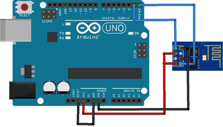
Connect the VCC and GND of ESP-01 to 3.3V and GND of Arduino also connect CH_PD to 3.3V and GPIO_0 to GND of Arduino. Connect RX and TX of ESP-01 to RX & TX of Arduino Uno respectively. GPIO_0 is grounded to enable the programming mode of ESP8266. After making the circuit as per the diagram, connect the Reset pin of the Arduino to GND to bypass the Arduino. It will disable Arduino and upload code directly to the ESP8266 board. Connect RST pin of ESP-01 to ground, remove the RST after half a second (the blue LED flashes for some millisecond).
Now, power up the Arduino Uno and open the Arduino IDE. Select the “Generic ESP8266 Module” in Board type and upload the code.
Circuit Diagram to Interface Neopixel with ESP8266
After uploading the code, remove the Arduino Uno and connect the Neopixel LED strip with ESP-01 as per the diagram.
![]()
VCC and CH_PD pins of ESP-01 are connected to the output pin of LM1117 while the GND pin is connected to the –ve rail of the 5V power supply. The data pin of the Neopixel LED is connected to the GPIO2 pin of ESP-01. This complete setup will be powered by a 5V Adapter. The LM117 voltage regulator is used to regulate 3.3V for the ESP8266-01 board.
After soldering all the components on the perf board, it will look something like below:
![]()
Setting up the Blynk App
Blynk is an application that can run on Android and iOS devices to control any IoT device. By using the Blynk app, the user can create their own Graphical User Interface to design the IoT application GUI. We previously used Blynk in many other IoT based projects.
Before the setup, download the Blynk Application from the Google Play store (iOS users can download it from Apple Store) and sign-up if you don’t have an account.
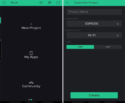
Creating a New Project:
After successful installation, open the application and click on “New Project”. On the next screen set the parameters like project name, board type, and connection type. For this project, select the device as “ESP8266” and connection type as Wi-Fi and click on “Create”.
Creating the GUI:
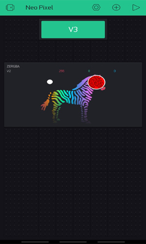
Open the project in Blynk, click on the “+” sign where it will show many widgets. In our case, we need an RGB Color Picker which is listed as “zeRGBa” and a Button that will be used for changing the mode of operation in the LED strip.
Setting the Parameter in Widgets:
After adding all the widgets, now set the widget parameters that are used to send the color and mode of control values to ESP-01.
Click on ZeRGBa, and we will get a screen named ZeRGBa Settings. Set the Output option to “Merge” and set the pin to “V2” as shown in the image below. Similarly, in Button settings, set the output pin to “V3” as shown in the figure below.
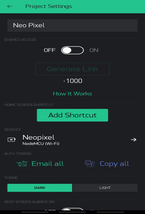
Getting the Auth Token:
Once you create a new project, Blynk mails you the Auth Token for that project. You can also get your Blynk auth token from your project page. Just click on the nut icon and copy the auth token using the copy all option and paste it somewhere safe. We will need it while programming the ESP-01.
Setting up IFTTT with Google Assistant and Blynk
IFTTT aka ‘If This, Then That’ is a web-based service to create chains of simple conditional statements, called Applets. It enables users to create triggers and execute actions based on the triggers. In this project, we are using IFTTT to create a trigger when we say a specific line using Google Assistant. For that, we have to create an applet in which we will integrate the Google Assistant with Blynk App using Webhooks.
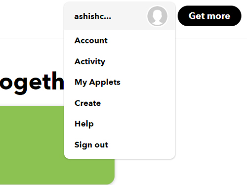
First of all, create an account on IFTTT. To do so, navigate to the IFTTT website and click on signup. Then fill your details and click on create an account. Now, as you are signed in to your account, click on your profile and then click on ‘Create.’
NOTE: Sign in to IFTTT using the same Email ID as used in your Android phone’s Google account. For example, if your phone is signed using the xyz@gmail.com Email ID, then sign in to IFTTT using the same Email ID.
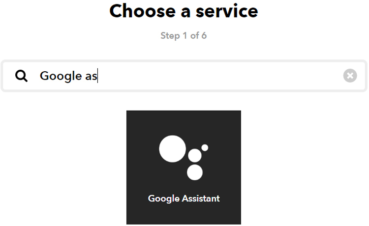
Now create an applet using If ‘This’ Then ‘That.’ Here ‘This’ is the service name by which we will give input and ‘That’ will generate trigger according to input. So in this project, we will use Google Assistant as ‘This’ and Webhooks as ‘That.’ So to create an applet, click on the ‘This’ icon and search for ‘Google Assistant.’ Here IFTTT will ask for permission for using your Google account.
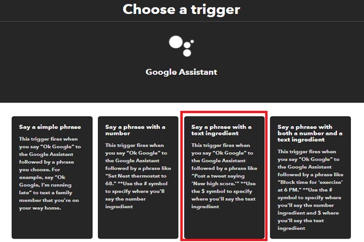
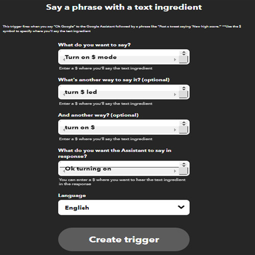
Now in Google Assistant, click on ‘Say a simple phrase with a text ingredient.’
Now in the next window, it will ask you about the phrase that you want to say to your Google Assistant and what you want to hear in response to that phrase. You can also add some optional phrases. Now click on 'Create Trigger'.
Now, one part of this applet is complete. For the second part, click on the ‘That.’

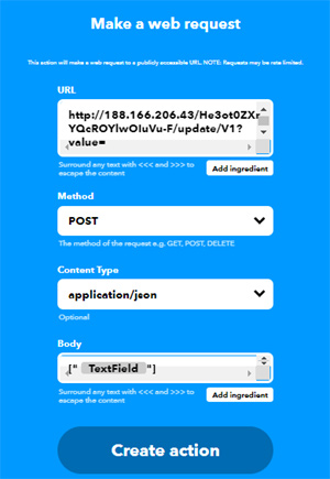
In the search window, search for ‘webhooks’, and in the next window click on ‘Make a web request’.

In the next window, enter the URL. The syntax of API is as below:
http://188.166.206.43/He3ot0ZXrYQcROYlwOIuVu-F/update/V1?value=
Where: 188.166.206.43 is the Blynk IP address in India, He3ot0ZXrYQcROYlwOIuVu-F is the Auth Token, and V1 is the virtual pin1.
3D Printed Casing for ESP-01
I measured the dimensions of the setup using the scale and also measured the dimensions of the barrel jack to design a casing for my setup. Once it was done, my design looked something like this.
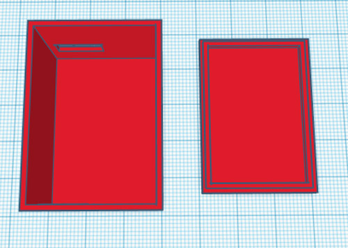
After finishing the design I exported it as an STL file, sliced it based on printer settings, and finally printed it. The STL file is also available for download from Thingiverse and you can print your casing using it. After the printing was done, I proceeded with assembling the project set up in a permanent enclosure to install it in a facility. With the complete connection made, I assembled the circuit into my casing and everything was a nice fit as you can see here.
![]()
Programming ESP-01 for Controlling Neopixel
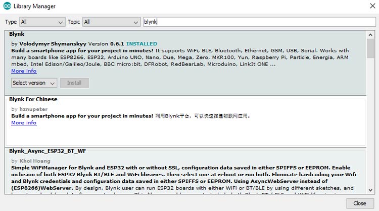
The complete code for Controlling Neopixel using Google Assistant can be found at the bottom of this page. The explanation of the same is as follows. In this project, we are going to use Adafruit_NeoPixel.h and BlynkSimpleEsp8266.h libraries. These libraries can be directly downloaded from Arduino IDE. For that, go to the Sketch > Include Library > Manage Libraries. Search for ‘Adafruit Neo’ in the search box and download, and install the Blynk ESP8266 library.
![]()
Follow the same procedure for installing the Blynk library for ESP8266.
After installing the libraries, begin the code by including all the required library files and defining the input and output pins
#include <Adafruit_NeoPixel.h>
#include <ESP8266WiFi.h>
#define BLYNK_PRINT Serial
#include <BlynkSimpleEsp8266.h>
#define PIXEL_PIN    2
#define PIXEL_COUNT 56
In the next lines, enter the Blynk and Wi-Fi credentials like auth token and the Wi-Fi name and password for the Wi-Fi to which ESP-01 should connect with. The blink auth token can be obtained from the Blynk application.
char auth[] = "wgdhfbm5uPqSp03bdMkxjr_VQwwCJ8Kw";
char ssid[] = "Galaxy-M20";
char pass[] = "ac312124";
After that, declare the NeoPixel strip object where Argument 1 is the number of pixels in the NeoPixel strip and Argument 2 is the ESP-01 pin where the LED strip is connected.
Adafruit_NeoPixel strip(PIXEL_COUNT, PIXEL_PIN, NEO_GRB + NEO_KHZ800);
The BLYNK_WRITE() function is used to check for incoming data at V1, V2, and V3 Virtual pins. The virtual pin V1 is for receiving the Google Assistant data from webhooks URL while V2 and V3 pins are used to change the Neopixel color and mode from the Blynk app.
BLYNK_WRITE(V1)
{
  ON_message = param.asStr();
  Serial.println (ON_message);
  }
BLYNK_WRITE(V2)
{
r = param[0].asInt();
g = param[1].asInt();
b = param[2].asInt();
if(data==0)
static1(r,g,b);
}
BLYNK_WRITE(V3)
{
data = param.asInt();
if(data==0)
{
  static1(r,g,b);
}
Inside the loop() function, Blynk.run() checks for incoming commands from Blynk GUI. The incoming string is then saved into a variable and using the if condition, it executes the operations accordingly.
void loop() {
      Blynk.run();
      if(ON_message.indexOf("off") >= 0)
  {
    colorWipe(strip.Color(  0,   0,   0), 50);
    delay(1000);
   }
  if(ON_message.indexOf("red") >= 0)
  {
    colorWipe(strip.Color(255,   0,   0), 50);    // Red
    delay(1000);
   }
…………………………….
Controlling Neopixel with Blynk and Google Assistant
Once your code and hardware are ready, upload the code on ESP-01 using Arduino Uno. After that, connect the Neopixel LED and say "Okay Google, turn on rainbow mode" or “turn on theatre mode” to your Google Assistant. Google Assistant will recognize the phrase and respond with "ok turning on" and Neopixel will illuminate according to the command. You can also use the Blynk to control the Neopixel color.
![]()
This is how you can control ESP8266 with Google Assistant. The complete working video and code for this project are given below. I hope you enjoyed building this project. If you have any questions, please leave them in the comment section.
#include <Adafruit_NeoPixel.h>
#include <ESP8266WiFi.h>
#define BLYNK_PRINT Serial
#include <BlynkSimpleEsp8266.h>
#define PIXEL_PIN 2 // Digital IO pin connected to the NeoPixels.
#define PIXEL_COUNT 56 // Number of NeoPixels
char auth[] = "wgdhfbm5uPqSp03bdMkxjr_VQwwCJ8Kw"; //get from blynk application
char ssid[] = "Galaxy-M20";
char pass[] = "ac312124";
Adafruit_NeoPixel strip(PIXEL_COUNT, PIXEL_PIN, NEO_GRB + NEO_KHZ800);
int mode = 0; // Currently-active animation mode, 0-9
int r,g,b,data;
String ON_message;
void setup() {
Serial.begin(9600);
Blynk.begin(auth, ssid, pass);
Serial.print("\n\nConnecting Wifi... ");
WiFi.begin(ssid, pass);
while (WiFi.status() != WL_CONNECTED)
{
delay(500);
}
Serial.println("OK!");
strip.begin(); // Initialize NeoPixel strip object (REQUIRED)
strip.show(); // Initialize all pixels to 'off'
}
void loop() {
Blynk.run();
if(ON_message.indexOf("off") >= 0)
{
colorWipe(strip.Color( 0, 0, 0), 50); // Black/off
delay(1000);
}
if(ON_message.indexOf("red") >= 0)
{
colorWipe(strip.Color(255, 0, 0), 50); // Red
delay(1000);
}
if(ON_message.indexOf("green") >= 0)
{
colorWipe(strip.Color( 0, 255, 0), 50); // Green
delay(1000);
}
if(ON_message.indexOf("blue") >= 0)
{
colorWipe(strip.Color( 0, 0, 255), 50); // Blue
delay(1000);
}
if(ON_message.indexOf("white") >= 0)
{
theaterChase(strip.Color(127, 127, 127), 50); // White
delay(1000);
}
if(ON_message.indexOf("theater") >= 0)
{
theaterChase(strip.Color(127, 0, 0), 50); // Red
delay(1000);
theaterChase(strip.Color( 0, 0, 127), 50); // Blue
delay(1000);
}
if(ON_message.indexOf("rainbow") >= 0)
{
rainbow(10);
delay(1000);
theaterChaseRainbow(50);
delay(1000);
}
}
BLYNK_WRITE(V1)
{
ON_message = param.asStr();
Serial.println (ON_message);
}
BLYNK_WRITE(V2)
{
r = param[0].asInt();
g = param[1].asInt();
b = param[2].asInt();
if(data==0)
static1(r,g,b);
}
BLYNK_WRITE(V3)
{
data = param.asInt();
Serial.println(data);
if(data==0)
{
static1(r,g,b);
}
else if(data==1)
{
animation1();
}
}
void static1(int r, int g, int b)
{
for(int i=0;i<=PIXEL_COUNT;i++)
{
strip.setPixelColor(i, strip.Color(r,g,b));
strip.show();
}
}
void animation1()
{
for(int i=0;i<PIXEL_COUNT;i++)
{
strip.setPixelColor(i, strip.Color(255,0,0));
strip.show();
delay(100);
}
for(int i=PIXEL_COUNT;i>=0;i--)
{
strip.setPixelColor(i, strip.Color(0,255,0));
strip.show();
delay(100);
}
for(int i=0;i<PIXEL_COUNT;i++)
{
strip.setPixelColor(i, strip.Color(0,255,255));
strip.show();
delay(100);
}
for(int i=PIXEL_COUNT;i>=0;i--)
{
strip.setPixelColor(i, strip.Color(255,255,0));
strip.show();
delay(100);
}
}
void colorWipe(uint32_t color, int wait) {
for(int i=0; i<strip.numPixels(); i++) { // For each pixel in strip...
strip.setPixelColor(i, color); // Set pixel's color (in RAM)
strip.show(); // Update strip to match
delay(wait); // Pause for a moment
}
}
void theaterChase(uint32_t color, int wait) {
for(int a=0; a<10; a++) { // Repeat 10 times...
for(int b=0; b<3; b++) { // 'b' counts from 0 to 2...
strip.clear(); // Set all pixels in RAM to 0 (off)
// 'c' counts up from 'b' to end of strip in steps of 3...
for(int c=b; c<strip.numPixels(); c += 3) {
strip.setPixelColor(c, color); // Set pixel 'c' to value 'color'
}
strip.show(); // Update strip with new contents
delay(wait); // Pause for a moment
}
}
}
void rainbow(int wait) {
for(long firstPixelHue = 0; firstPixelHue < 3*65536; firstPixelHue += 256) {
for(int i=0; i<strip.numPixels(); i++) { // For each pixel in strip...
int pixelHue = firstPixelHue + (i * 65536L / strip.numPixels());
strip.setPixelColor(i, strip.gamma32(strip.ColorHSV(pixelHue)));
}
strip.show(); // Update strip with new contents
delay(wait); // Pause for a moment
}
}
void theaterChaseRainbow(int wait) {
int firstPixelHue = 0; // First pixel starts at red (hue 0)
for(int a=0; a<30; a++) { // Repeat 30 times...
for(int b=0; b<3; b++) { // 'b' counts from 0 to 2...
strip.clear(); // Set all pixels in RAM to 0 (off)
for(int c=b; c<strip.numPixels(); c += 3) {
int hue = firstPixelHue + c * 65536L / strip.numPixels();
uint32_t color = strip.gamma32(strip.ColorHSV(hue)); // hue -> RGB
strip.setPixelColor(c, color); // Set pixel 'c' to value 'color'
}
strip.show(); // Update strip with new contents
delay(wait); // Pause for a moment
firstPixelHue += 65536 / 90; // One cycle of color wheel over 90 frames
}
}
}


