


IoT development is going with the pace and with this development, it requires more number of nodes to be connected with the internet. But there is a limitation of node connections that can be directly connected to the same router. Approximately 32 nodes can be connected to the same router, this problem makes it costly and time-consuming task.
What if we don’t require the router anymore to expand our IoT networks. Yes, it can be removed from the network or only a few routers can be used to connect a large number of nodes with the internet. This is where Mesh Networking comes in to picture.
What is Mesh Networking?
Mesh networking is the local network topology in which nodes are directly, dynamically and non-hierarchically connected to each other and cooperates with one another to efficiently route the data from/to clients. As a result, the large number of nodes can be connected with the internet without adding the number of routers to the network. We can connect up to 87 nodes with a single router as shown below.
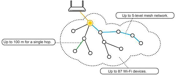
Mesh network supports auto-networking which means that when the user setup a mesh network, any node can scan this Access point and can connect easily.
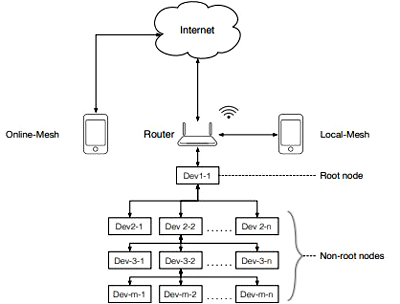
As shown above, there is a network diagram in which a router is connected to the internet and there is a root node that is connected directly to the router and other nodes are called non-roots nodes. So, in this way, we can connect many nodes using just one router and can control these nodes using the internet or locally.
Now, the good news is that ESP8266, ESP-12 and ESP32 also support mesh networking using a Wi-Fi network. There is official documentation available online where you can find how ESP works in Mesh network and how to write sample code.
In this tutorial, we will make local ESP mesh network using three NodeMCU (ESP-12e) by controlling LEDs/Relays connected to different NodeMCUs with push buttons attached to the other NodeMCU. We will also send the DHT11 temperature and humidity readings to the other nodes.
So, let’s get started.
Components Required
- NodeMCU (at least 2- any ESP8266, ESP32 or ESP12)
- DHT11 Temperature and Humidity Sensor (any other sensor)
- Push Buttons
- LEDs or relay modules
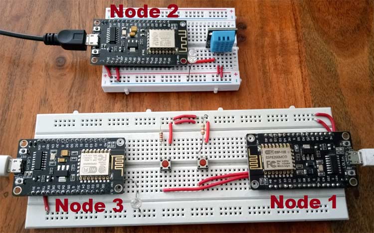
NodeMCU Wi-Fi Mesh Network Circuit Diagram
Here three NodeMCUs are used to demonstrate NodeMCU Wi-Fi Mesh Network:
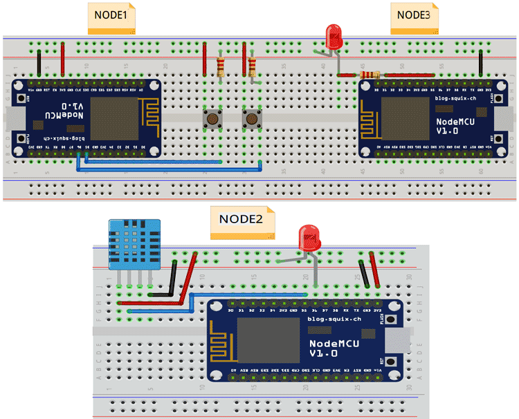
Connections:
Node1: Connect push buttons at pin D5 and D6.
Node2: Connect DHT11 at D5 and LED at D6.
Node3: Connect LED at D5.
Programming NodeMCU for Mesh Networking
Here Arduino IDE will be used to program ESP12 NodeMCU, for that we need some board file for ESP12. Follow our previous ESP8266 tutorials to learn how to program NodeMCU using Arduino IDE or check this IoT parking system tutorial.
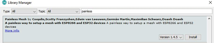
Here a library will be used to create a mesh network. There is a library called painlessMesh which is completely painless to use and responsible for creating and structuring the network. You can find the documentation of this library on github.
To install this library, open Arduino IDE go to Sketch->Include Library->Manage Libraries and search for the painlessMesh and install the latest version of it as shown below.
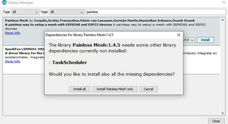
This library also uses ArduinoJson, TaskScheduler, ESPAsyncTCP and AsyncTCP libraries. When you click on install it will ask to install these libraries also. So, click on “Install All”.
This library supports ArduinoJson version 6.0 and above. So, after installing the painlessmesh library, search for ArduinoJson and make sure version 6.0 and higher should be installed.
Some Important notes before programming NodeMCU:
- PainlessMesh library uses JSON objects for all its messaging. Using JSON we can easily send and receive data from different nodes.
- PainlessMesh is not an IP networking so there is no TCP/IP of nodes. Each node in the network is uniquely identified using its 32-bit chip which can be found using system_get_chip_id() function.
- Avoid using delay() function in the programming as it stops the CPU. To maintain the mesh, we need to perform some tasks in the background so if the delay is used then this background task also stops and the connection between the nodes can be lost.
Now, we are ready to write code for the NodeMCU mesh network.
Code Explanation
Here we have three nodes (three NodeMCU ESP12)
Node1: It has 2 pushbuttons to control LEDs on the other 2 Nodes.
Node2: It has a DHT11 sensor and 1 LED. It will send temperature and humidity data to Node1 and Node3.
Node3: It has one LED.
So, there will be three separate codes for each node.
Code for Node1:
1. First, include the painlessMesh header file.
#include "painlessMesh.h"
2. Define the Wi-Fi credentials for the mesh network. It includes SSID, password and port number. These three parameters should remain the same for every node in the network.
#define   MESH_PREFIX     "**********"
#define   MESH_PASSWORD   "********"
#define   MESH_PORT       5555
Port number can be any number except the pre-defined port numbers for other web tools. You can use as given above.
3. Make instances for painlessMesh and Scheduler.
Scheduler userScheduler;
painlessMesh  mesh;
4. Define the Pin numbers of NodeMCU on which two pushbuttons are connected. I am using D5 and D6. Also, initialize the button state.
#define Button1 D5
#define Button2 D6
bool button1_status = 0;
bool button2_status = 0;
5. Now, we have to make two functions. One for sending messages and other for receiving. In the first node, send the status of pushbuttons and receive the temperature and humidity data in the network.
In sendMessage() function, check for the digital pin value. If it is HIGH then just toggle the button status using the NOT(!) operator.
void sendMessage()
{
  if (digitalRead(Button1) == HIGH)
    button1_status = !button1_status;
  if (digitalRead(Button2) == HIGH)
    button2_status = !button2_status;
Then send this button status value to the network using JSON. For this purpose, DynamicJsonDocument is used. We define an instance to use this with the size of the document as shown.
DynamicJsonDocument doc(1024);
Now, store the button status values in two different doc variables.
  doc["LED1"] = button1_status;
  doc["LED2"] = button2_status;
This doc data is converted into a string using serializeJson() function.
  String msg ;
  serializeJson(doc, msg);
Now, send this message in the mesh network using mesh.sendBroadcast(); after a fixed interval.
mesh.sendBroadcast( msg );
  Serial.println(msg);
  taskSendMessage.setInterval((TASK_SECOND * 1));
}
6. Whenever there will be a message in the network, receive callback function comes in the action. This function takes two arguments, node ID and message. As data is serialized in sending function, it must be deserialized while receiving.
void receivedCallback( uint32_t from, String &msg ) {
  String json;
  DynamicJsonDocument doc(1024);
  json = msg.c_str();
  DeserializationError error = deserializeJson(doc, json);
Then store fetched data into a string variable and display it on the serial monitor.
   String Temp = doc["TEMP"];
   String Hum = doc["HUM"];
   Serial.println("Temperature:");
   Serial.print(Temp);
    Serial.println("Humidity:");
   Serial.print(Hum);
}
7. In the void setup function, start the serial communication with 115200baud rate, define pinMode as input for the pushbuttons.
void setup() {
  Serial.begin(115200);
  pinMode(Button1, INPUT);
  pinMode(Button2, INPUT);
Start with the debug function which is used to get any error occurred while making a connection with the nodes.
mesh.setDebugMsgTypes( ERROR | STARTUP );
Initialize the mesh bypassing the SSID, password, port number and scheduler address.
mesh.init( MESH_PREFIX, MESH_PASSWORD, &userScheduler, MESH_PORT );
Now, we will call all the callback functions one by one. Every time a node receives a message, below callback routine will be called.
mesh.onReceive(&receivedCallback) - When a new node make connection this callback is called.
mesh.onNewConnection(&newConnectionCallback)- When there is a change in mesh topology this callback is called.
mesh.onChangedConnections(&changedConnectionCallback)- This fires every time local time is adjusted to synchronize it with mesh time.
mesh.onNodeTimeAdjusted(&nodeTimeAdjustedCallback)- When any callback fired then scheduler executes the task and send the appropriate message to nodes
  userScheduler.addTask( taskSendMessage );
  taskSendMessage.enable();
}
8. Now, we have to implement all the callback functions as shown below.
void newConnectionCallback(uint32_t nodeId) {
  Serial.printf("--> startHere: New Connection, nodeId = %u\n", nodeId);
}
void changedConnectionCallback() {
  Serial.printf("Changed connections\n");
}
void nodeTimeAdjustedCallback(int32_t offset) {
  Serial.printf("Adjusted time %u. Offset = %d\n", mesh.getNodeTime(), offset);
}
9. In void loop() functions, just add mesh.update() function. This routine runs various maintenance tasks and things will not work if it is missing.
void loop() {
  mesh.update();
}
Here the code for Node1 is finished.
Code for Node2:
For Node2, the structure will remain the same. Only send and receive functions will have slight changes. In send message function, just get the readings from the DHT sensor using the DHT temperature and humidity functions and serialize the data as shown below.
void sendMessage()
{
  // Serializing in JSON Format
  DynamicJsonDocument doc(1024);
  float h = dht.readHumidity();
  float t = dht.readTemperature();
  doc["TEMP"] = t;
  doc["HUM"] = h;
  String msg ;
  serializeJson(doc, msg);
  mesh.sendBroadcast( msg );
  Serial.println(msg);
  taskSendMessage.setInterval((TASK_SECOND * 10));
}
In receiving function, just deserialize the message and write the values to the digitalwrite function to toggle the led.
void receivedCallback( uint32_t from, String &msg ) {
  String json;
  DynamicJsonDocument doc(1024);
  json = msg.c_str();
  DeserializationError error = deserializeJson(doc, json);
  if (error)
  {
    Serial.print("deserializeJson() failed: ");
    Serial.println(error.c_str());
  }
  relay1_status = doc["Relay1"];
  digitalWrite(Relay1, relay1_status);
}
Similarly, modify the above code for the Node3. All the codes for three nodes can be found at the end of this tutorial.
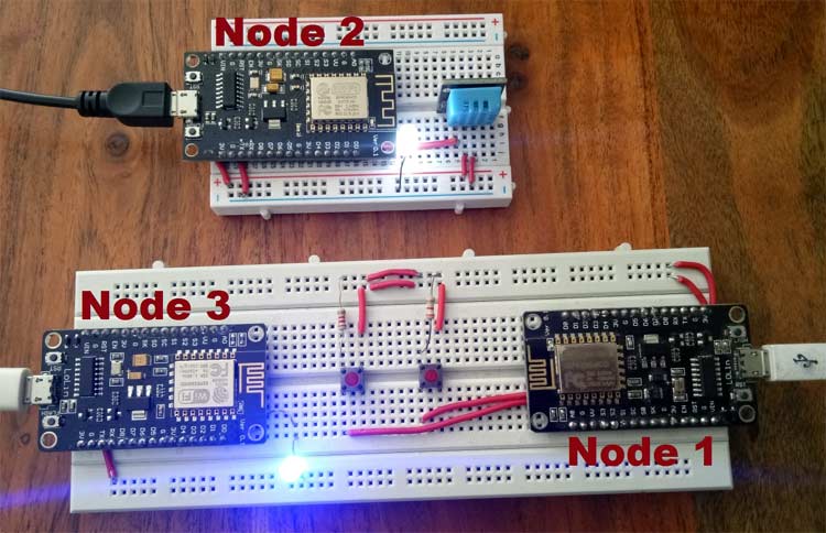
Finally, make the circuit according to the circuit diagram and upload the code in each NodeMCU.
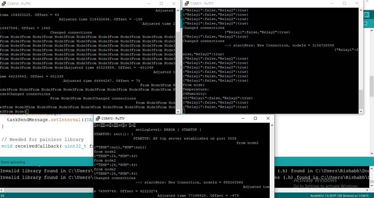
Now, to observe the data coming from all the nodes you have to use Putty or any other serial software because the serial monitor in Arduino IDE will display only single port data at a time.
In putty, click on the serial option and enter the com port of each NodeMCU and speed as 115200. Open three terminals and you will see the data of each node on the respective terminal as shown below.
In this way, different projects can be made using NodeMCU mesh networking like home automation, Smart farming, etc by deploying nodes in different places. Also, you can use NodeMCU ESP8266 or ESP32 to create a Mesh Network.
Code for Node1:
#include "painlessMesh.h"
// WiFi Credentials
#define MESH_PREFIX "whateverYouLike"
#define MESH_PASSWORD "somethingSneaky"
#define MESH_PORT 5555
bool button1_status = 0;
bool button2_status = 0;
//Pin Declaration
#define Button1 D5
#define Button2 D6
Scheduler userScheduler;
painlessMesh mesh;
void sendMessage() ;
Task taskSendMessage( TASK_SECOND * 1 , TASK_FOREVER, &sendMessage );
void sendMessage()
{
// Reading Status of Pushbutton
if (digitalRead(Button1) == HIGH)
button1_status = !button1_status;
if (digitalRead(Button2) == HIGH)
button2_status = !button2_status;
// Serializing in JSON Format
DynamicJsonDocument doc(1024);
doc["Relay1"] = button1_status;
doc["Relay2"] = button2_status;
String msg ;
serializeJson(doc, msg);
mesh.sendBroadcast( msg );
Serial.println(msg);
taskSendMessage.setInterval((TASK_SECOND * 1));
}
void receivedCallback( uint32_t from, String &msg ) {
String json;
DynamicJsonDocument doc(1024);
json = msg.c_str();
DeserializationError error = deserializeJson(doc, json);
if (error)
{
Serial.print("deserializeJson() failed: ");
Serial.println(error.c_str());
}
String Temp = doc["TEMP"];
String Hum = doc["HUM"];
Serial.println("From node1");
Serial.println("Temperature:");
Serial.print(Temp);
Serial.println("Humidity:");
Serial.print(Hum);
}
void newConnectionCallback(uint32_t nodeId) {
Serial.printf("--> startHere: New Connection, nodeId = %u\n", nodeId);
}
void changedConnectionCallback() {
Serial.printf("Changed connections\n");
}
void nodeTimeAdjustedCallback(int32_t offset) {
Serial.printf("Adjusted time %u. Offset = %d\n", mesh.getNodeTime(), offset);
}
void setup() {
Serial.begin(115200);
pinMode(Button1, INPUT);
pinMode(Button2, INPUT);
mesh.setDebugMsgTypes( ERROR | STARTUP ); // set before init() so that you can see startup messages
mesh.init( MESH_PREFIX, MESH_PASSWORD, &userScheduler, MESH_PORT );
mesh.onReceive(&receivedCallback);
mesh.onNewConnection(&newConnectionCallback);
mesh.onChangedConnections(&changedConnectionCallback);
mesh.onNodeTimeAdjusted(&nodeTimeAdjustedCallback);
userScheduler.addTask( taskSendMessage );
taskSendMessage.enable();
}
void loop() {
mesh.update();
}
Code for Node2:
#include "painlessMesh.h"
#include <DHT.h>
// WiFi Credentials
#define MESH_PREFIX "whateverYouLike"
#define MESH_PASSWORD "somethingSneaky"
#define MESH_PORT 5555
//Pin Declaration
#define Relay1 D6
#define DHTPIN D5
#define DHTTYPE DHT11 // DHT 11
DHT dht(DHTPIN, DHTTYPE);
//Variables
bool relay1_status = 0;
Scheduler userScheduler;
painlessMesh mesh;
void sendMessage() ;
Task taskSendMessage( TASK_SECOND * 1 , TASK_FOREVER, &sendMessage );
void sendMessage()
{
// Serializing in JSON Format
DynamicJsonDocument doc(1024);
float h = dht.readHumidity();
float t = dht.readTemperature();
doc["TEMP"] = t;
doc["HUM"] = h;
String msg ;
serializeJson(doc, msg);
mesh.sendBroadcast( msg );
Serial.println("from node2");
Serial.println(msg);
taskSendMessage.setInterval((TASK_SECOND * 10));
}
// Needed for painless library
void receivedCallback( uint32_t from, String &msg ) {
String json;
DynamicJsonDocument doc(1024);
json = msg.c_str();
DeserializationError error = deserializeJson(doc, json);
if (error)
{
Serial.print("deserializeJson() failed: ");
Serial.println(error.c_str());
}
relay1_status = doc["Relay1"];
digitalWrite(Relay1, relay1_status);
}
void newConnectionCallback(uint32_t nodeId) {
Serial.printf("--> startHere: New Connection, nodeId = %u\n", nodeId);
}
void changedConnectionCallback() {
Serial.printf("Changed connections\n");
}
void nodeTimeAdjustedCallback(int32_t offset) {
Serial.printf("Adjusted time %u. Offset = %d\n", mesh.getNodeTime(), offset);
}
void setup() {
Serial.begin(115200);
pinMode(Relay1, OUTPUT);
mesh.setDebugMsgTypes( ERROR | STARTUP ); // set before init() so that you can see startup messages
mesh.init( MESH_PREFIX, MESH_PASSWORD, &userScheduler, MESH_PORT );
mesh.onReceive(&receivedCallback);
mesh.onNewConnection(&newConnectionCallback);
mesh.onChangedConnections(&changedConnectionCallback);
mesh.onNodeTimeAdjusted(&nodeTimeAdjustedCallback);
userScheduler.addTask( taskSendMessage );
taskSendMessage.enable();
}
void loop() {
mesh.update();
}
Code for Node3:
#include "painlessMesh.h"
// WiFi Credentials
#define MESH_PREFIX "whateverYouLike"
#define MESH_PASSWORD "somethingSneaky"
#define MESH_PORT 5555
//Pin Declaration
#define Relay2 D5
//Variables
bool relay2_status = 0;
Scheduler userScheduler;
painlessMesh mesh;
void sendMessage() ;
Task taskSendMessage( TASK_SECOND * 1 , TASK_FOREVER, &sendMessage );
void sendMessage()
{
}
// Needed for painless library
void receivedCallback( uint32_t from, String &msg ) {
String json;
DynamicJsonDocument doc(1024);
json = msg.c_str();
DeserializationError error = deserializeJson(doc, json);
if (error)
{
Serial.print("deserializeJson() failed: ");
Serial.println(error.c_str());
}
relay2_status = doc["Relay2"];
digitalWrite(Relay2, relay2_status);
Serial.printf("From Node3");
}
void newConnectionCallback(uint32_t nodeId) {
Serial.printf("--> startHere: New Connection, nodeId = %u\n", nodeId);
}
void changedConnectionCallback() {
Serial.printf("Changed connections\n");
}
void nodeTimeAdjustedCallback(int32_t offset) {
Serial.printf("Adjusted time %u. Offset = %d\n", mesh.getNodeTime(), offset);
}
void setup() {
Serial.begin(115200);
pinMode(Relay2, OUTPUT);
mesh.setDebugMsgTypes( ERROR | STARTUP ); // set before init() so that you can see startup messages
mesh.init( MESH_PREFIX, MESH_PASSWORD, &userScheduler, MESH_PORT );
mesh.onReceive(&receivedCallback);
mesh.onNewConnection(&newConnectionCallback);
mesh.onChangedConnections(&changedConnectionCallback);
mesh.onNodeTimeAdjusted(&nodeTimeAdjustedCallback);
userScheduler.addTask( taskSendMessage );
taskSendMessage.enable();
}
void loop() {
// it will run the user scheduler as well
mesh.update();
}


