


GPS stands for Global Positioning System, which is a worldwide radio-navigation system. To track the location of the device, the GPS tracking system uses the Global Navigation Satellite System (GNSS) Network. This network consists of a range of satellites that uses microwave signals to transmit the data which will be received by the GPS receiver module.
Previously we used GPS with NodeMCU ESP8266 to build a Vehicle Tracking System and Accident alert system. In this project, we are going to build an IoT based GPS Vehicle Tracking System using ESP32 where we will display the latitude and longitude values on OLED Display as well as on Blynk App so that it can be monitored from anywhere in the world.
Components Required
- ESP32
- GPS Module
- OLED Display Module
- Jumper Wires
- Breadboard
OLED Display
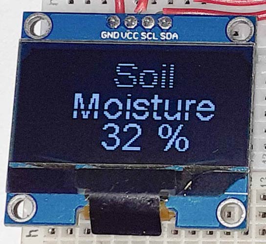
The OLED displays are one of the most common and easily available displays for a microcontroller. This display can easily be interfaced with microcontroller using IIC or using SPI communication and has a good view angle and pixel density which makes it reliable for displaying small level graphics. It is compatible with any 3.3V-5V microcontroller, such as Arduino. The OLED display comes with a powerful single-chip CMOS OLED driver controller – SSD1306 that handles the entire RAM buffering. The SSD1306 driver has a built-in 1KB Graphic Display Data RAM (GDDRAM). We previously interfaced OLED with ESP32.
Specifications:
- OLED Driver IC: SSD1306
- Resolution: 128 x 64
- Visual Angle: >160°
- Input Voltage: 3.3V ~ 6V
- Pixel Colour: Blue
- Working temperature: -30°C ~ 70°C
Neo 6M GPS Module
The NEO-6M module comes with a dimension of 16 x 12.2 x 2.4 mm package. It has 6 Ublox positioning engines offering unmatched performance. It is a good performance GPS receiver with a compact architecture, low power consumption, and reliable memory options. It is ideal for battery-operated mobile devices considering its architecture and power demands. The Time-to-First-Fix is less than 1 second and it enables it to find the satellites almost instantly. The output is in the format of NMEA standards, which can be decoded to find the coordinates and Time of the location.
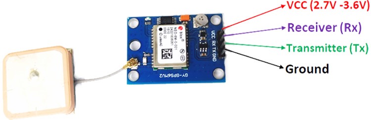
- Power supply: 2.8V to 5V
- Interface: RS232 TTL
- Built-in EEPROM and external antenna
- Default baud rate: 9600 bps
We previously used GPS module Neo 6M with NodeMCU and displayed the location coordinates on a web-page, check all the GPS based IoT projects here.
Circuit Diagram
Circuit Diagram for ESP32 GPS NEO 6M is given below.
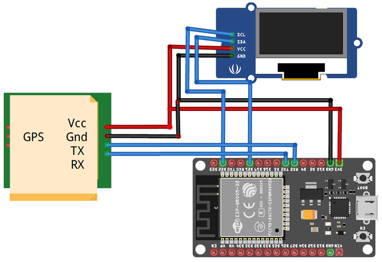
Here we are interfacing the ESP32 with GPS Module and OLED Display. Vcc and GND pin of GPS Module is connected to 3.3V and GND of ESP32 while the RX and TX pins are connected to TX2 and RX2 pins of ESP32. I2C mode is used to connect the OLED display Module (SSD1306) with ESP32. Connections between ESP32 and OLED Display are given as:
|
OLED Pin |
ESP32 Pin |
|
Vcc |
3.3v |
|
GND |
GND |
|
SCL |
D22 |
|
SDA |
D21 |
Configuring Blynk App for ESP32 GPS Tracker
Download the Blynk app from the Google Play Store and create a new account or Login into your existing account.
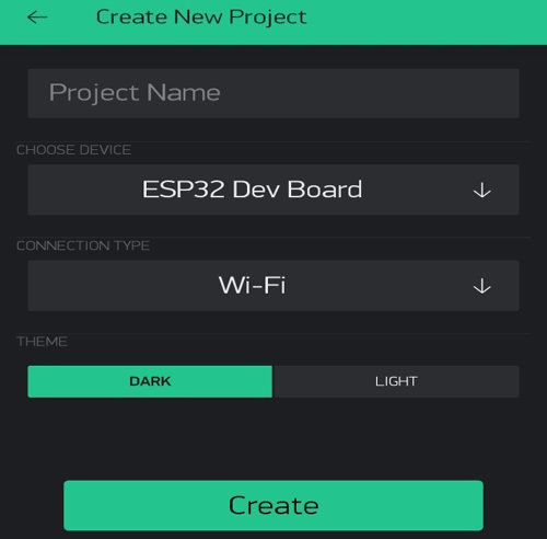
Now click on ‘New Project’ to start a new project.
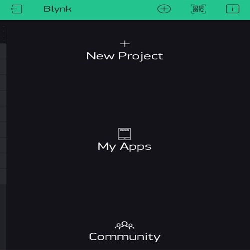
Now give a name for your project. Select ‘ESP32 Dev Board’ in the CHOOSE DEVICE option and ‘Wi-Fi’ in CONNECTION TYPE. Then click on ‘Create.’
After this, Blynk will send an Authorization to the registered Email id. Note down the Auth Token Code. It will be used in the Program.
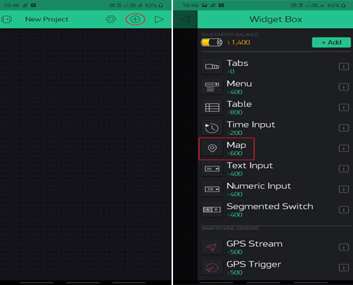
Now in the next window, click on the “+” sign to add a widget. Inside the Widget box, select the ‘Map’ widget.
After this, click on the MAP widget and select virtual pin ‘V0’ as INPUT.
![]()
With this final step, you are ready to use your app. By pressing the ‘Play’ button, you can switch your app from EDIT mode to PLAY mode where you can interact with the hardware.
Code Explanation
The complete code for ESP32 GPS Tracking System is given at the end of the page. Here we are explaining some important parts of code.
In this program, we are going to use the Wire.h, TinyGPS++.h, SH1106.h and BlynkSimpleEsp32.h libraries. These libraries can be downloaded from below links:
So as usual, start the code by including all the required libraries. SH1106.h is especially created for ESP modules.
#include <TinyGPS++.h>
#include <HardwareSerial.h>
#include <WiFi.h>
#include <Wire.h>
#include<SH1106.h>
#include <BlynkSimpleEsp32.h>
After that define the variables to store the Latitude and Longitude values.
float latitude, longitude;
String lat_str, lng_str;
In the next lines, enter your Wi-Fi name and password and also enter the Blynk Authorization key.
const char *ssid = "Wi-Fi Name"; // Enter your Wi-Fi Name
const char *pass = "Wi-Fi Password"; // Enter your Wi-Fi Password
char auth[] = "Blynk Key";
After that, create an instance for the OLED display that includes the Address and pins where the display is connected.
SH1106 display(0x3c, 21, 22);
Inside the setup() function, initialize the Serial Monitor at a baud rate of 115200 for debugging purposes and also initialize the OLED display, GPS module, and Blynk with the begin() method.
void setup()
{
  Serial.begin(115200);
  Serial.println(ssid);
  WiFi.begin(ssid, pass);
  while (WiFi.status() != WL_CONNECTED)
  {
  }
  Serial.println("WiFi connected");
  display.init();
  display.flipScreenVertically();
  display.setFont(ArialMT_Plain_10);
  SerialGPS.begin(9600, SERIAL_8N1, 16, 17);
  Blynk.begin(auth, ssid, pass);
  Blynk.virtualWrite(V0, "clr");
}
Inside the loop() function, check if there is incoming data from the GPS module. If the data is available, the code encodes the data and checks if the encoded data is valid or not, if the data is valid, then the further calculation is done to transform the NMEA data to the understandable data.
while (SerialGPS.available() > 0) {
    if (gps.encode(SerialGPS.read()))
    {
      if (gps.location.isValid())
      {
        latitude = gps.location.lat();
        lat_str = String(latitude , 6);
        longitude = gps.location.lng();
        lng_str = String(longitude , 6);
After this, the GPS data is sent to the Blynk app and OLED display. Blynk app uses the Map widget to pinpoint the user's location using the latitude and longitude data.
        display.setTextAlignment(TEXT_ALIGN_LEFT);
        display.setFont(ArialMT_Plain_16);
        display.drawString(0, 23, "Lat:");
        display.drawString(45, 23, lat_str);
        display.drawString(0, 38, "Lng:");
        display.drawString(45, 38, lng_str);
        Blynk.virtualWrite(V0, 1, latitude, longitude, "Location");
Working of ESP32 GPS Tracking System
Once the hardware and the program are ready, upload the GPS tracking program into your ESP32 Board. Here Arduino IDE is used to upload the ESP32 GPS NEO 6M code to ESP32 board, so connect the ESP32 to your laptop with a Micro USB Cable and hit the upload button. Once the code is uploaded, the OLED will display the Latitude and Longitude values. It will also show the location in the Blynk app on Map like this:
![]()
A working video and code for this IoT based ESP32 GPS Tracker are given below.
#include <TinyGPS++.h>
#include <HardwareSerial.h>
#include <WiFi.h>
#include <Wire.h> // Only needed for Arduino 1.6.5 and earlier
#include<SH1106.h>
#include <BlynkSimpleEsp32.h>
float latitude , longitude;
String lat_str , lng_str;
const char *ssid = "Galaxy-M20"; // Enter your WiFi Name
const char *pass = "ac312129"; // Enter your WiFi Password
char auth[] = "loPrSaL0eQFY9clcQ518R1SmYsRVC0eV";
WidgetMap myMap(V0);
SH1106 display(0x3c, 21, 22);
WiFiClient client;
TinyGPSPlus gps;
HardwareSerial SerialGPS(1);
void setup()
{
Serial.begin(115200);
Serial.println("Connecting to ");
Serial.println(ssid);
WiFi.begin(ssid, pass);
while (WiFi.status() != WL_CONNECTED)
{
delay(500);
Serial.print("."); // print ... till not connected
}
Serial.println("");
Serial.println("WiFi connected");
display.init();
display.flipScreenVertically();
display.setFont(ArialMT_Plain_10);
SerialGPS.begin(9600, SERIAL_8N1, 16, 17);
Blynk.begin(auth, ssid, pass);
Blynk.virtualWrite(V0, "clr");
}
void loop()
{
while (SerialGPS.available() > 0) {
if (gps.encode(SerialGPS.read()))
{
if (gps.location.isValid())
{
latitude = gps.location.lat();
lat_str = String(latitude , 6);
longitude = gps.location.lng();
lng_str = String(longitude , 6);
Serial.print("Latitude = ");
Serial.println(lat_str);
Serial.print("Longitude = ");
Serial.println(lng_str);
display.clear();
display.setTextAlignment(TEXT_ALIGN_LEFT);
display.setFont(ArialMT_Plain_16);
display.drawString(0, 23, "Lat:");
display.drawString(45, 23, lat_str);
display.drawString(0, 38, "Lng:");
display.drawString(45, 38, lng_str);
Blynk.virtualWrite(V0, 1, latitude, longitude, "Location");
display.display();
}
delay(1000);
Serial.println();
}
}
Blynk.run();
}


