


It is important to maintain the safety and hygiene of the food to keep it fresh and edible which helps in decreasing the food wastage. One solution for this is to maintain suitable environmental conditions for the stored food to control the rate of decomposition. There are different parameters on which food decomposition depends, the parameters like humidity, bacteria, and temperature are major factors on which the rate of decomposition of food depends on. If the temperature of the storage is between 40F to 140F, it is a danger zone because during that temperature bacteria grow rapidly, doubling its number in 20 min. Similarly, the humidity in the food storage room should be around 50-55% to keep the quality of the food at high, as long as possible.
So in this IoT project, we will build a Food Monitoring device using NodeMCU and Arduino IDE, to monitor the temperature and humidity of the stored environment and control it. To control the temperature, we are going to use a DC motor as a cooling mechanism. To find the temperature, and humidity the DHT11 sensor module is used, and to determine the status of the food, the MQ4 gas sensor module is used. In the future, if needed we can also use an IoT based Weight sensor to also monitor the food quantity in the storage area.
The real-time values of the temperature, humidity, and methane gas will be measured and sent over the web to be displayed on it. If the temperature is at the critical value, we will receive an email warning, and the fan will also be automatically controlled. You can also check this article on how IoT is used in the food industry to find out other ways in which the food industry can be modernized.
Hardware Required
- NodeMCU ESP8266
- MQ3 Sensor Module
- DHT11 Sensor module
- DC motor
- BC547-BJT
- Battery
- Connecting wires
- RPS
Circuit Diagram
The complete circuit diagram for this Food Monitoring project is given in the image below.
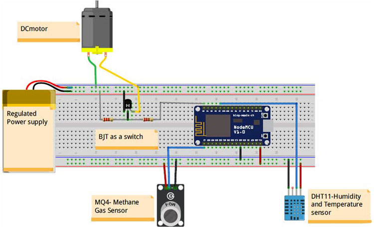
The power to the motor is given by the regulated power supply. The positive terminal of the RPS is connected to the positive terminal of the motor; the negative terminal of the motor is connected to the collector terminal of the BJT. The emitter terminal of the BJT is grounded, and the base terminal of the BJT is connected to the D0 pin of the MCU with a current limiting resistor 1K. The base terminal of the BJT is connected to ground with a resistor whose value is greater than the current limiting resistor. This resistor acts as a push-down resistor to the BJT. The VCC and GND of the MCU are connected to the one side of the power rails as shown in the fig below. The positive terminal and GND terminal of both the sensors are connected to the VCC and GND power rails as shown in the figure above. The A0 pin of the gas sensor is connected to the A0 pin of the MCU while the data of the DHT11 sensor is connected to the D4 pin of the MCU.
The two main important sensors here are the MQ-4 Gas Sensor and the DHT11 Temperature and Humidity Sensor. Let’s look into the detail of them. If you do not want the explanation, you can directly scroll down to the bottom of this page to get the complete code of this project.
MQ4 Gas Sensor Module
MQ4 is a gas sensing module, which is used to measure methane gas in the atmosphere. It contains Gas sensing layer, which is made up of SnO2. SnO2 is sensitive to gases like LPG, CH4, H2, CO, Alcohol, and smoke. As the decaying food emits methane gas (CH4), the MQ4 sensor can be used to measure this gas to monitor food quality. You can also check this MQ135 sensor interfacing project where we used a similar gas sensor to monitor air quality by measuring PPM.
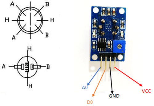
Along with SnO2, the sensor consists of an Al2O3 ceramic tube, measuring electrode, and heating element. The heating element provides the necessary working conditions for the sensor to operate. The MQ4 sensor is available in two formats in the market, in module format or only sensor format. The sensor module has 4 pins in which we are going to use only 3 pins in our project. They are VCC, GND, and A0. We leave the D0 pin, as it is not useful in the calculation of the ppm. The working of the MQ4 sensor is similar to that of LDR (light dependent resistor). When the concentration of the methane gas is high, the module's resistance decreases, and when the concentration is low, the resistance increases.
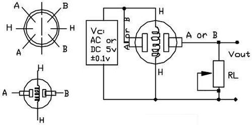
MQ4 Gas Sensor Internal Circuit
Both A terminals are shorted, and both B terminals are shorted, leaving only 4 connections to connect in the circuit. The terminal H is used to connect supply voltage to the heating element, which is made up of Ni-Cr alloy. It is used to provide necessary work conditions for the sensitive component. The supply voltage is given to either of the H terminals along with A or B terminal. RL is the load resistance, which we have to add to the sensor, as shown in the pic. If you have a sensor module, check out the PCB tracks and find the RL value and measure its value using a multimeter.
Interfacing MQ4 Sensor with NodeMCU ESP8266
Before we get into the main project, we have to calibrate the MQ4 sensor so that we can measure the ppm value from the gas sensor. Connect your gas sensor with NodeMCU as shown in the below image.
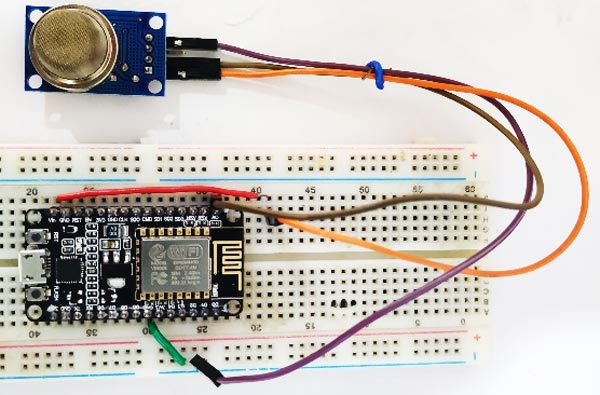
The VCC and GND pin of the Sensor Module is connected to the Vin of NodeMCU. The A0 pin of the sensor module is connected with the A0 pin of the Microcontroller.
Calibration of the MQ4 Gas Sensor:
We need to find the ratio (RS/R0) in order to determine the methane content present in the air. The R0 and RS are the internal resistance values of the fresh air.
We are going to find the value of RS from VRL (voltage across resistor RL). By using a microcontroller, we can find the value of voltage (VRL) across the Rl (load resistance). To find the RS from the VRL, we need to derive the formula. The equivalent circuit of fig 1 is shown below, and this equivalent circuit is used to derive the formula which is used to find the RS value from VRL.
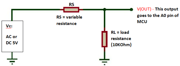
The voltage across the RL load is VL = I * RL, substituting for I, we get VL = (V*RL) / (RS+RL). Simply the equation to get Rs.
From the equivalent circuit, we get the equation
 V = I (RS +RL)
I = V / (RS+RL)
RS = ((V-VL)/VL)*RL
Where V is the supply voltage.
Calculate Value of R0 in the Fresh Air:
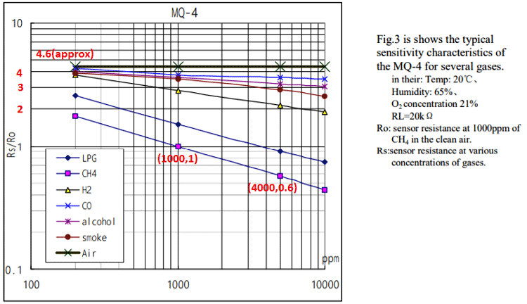
Now, we are going to find the value of R0 using the value of RS and the graph present in the datasheet which is shown below.

By seeing the graph we can find that the X-axis is ppm, and Y-axis is RS/R0. Trace out the value of R0/RS of fresh air. In our case, it is around 4.6. You have RS value (which is found previously using VRL), and now you can find R0 using the relation R0/RS = 4.6. In my case, I got the value of R0 as 1.9.
The Arduino program to calculate R0 of the gas sensor is given below. Follow the above circuit and upload the below code. Then open the serial monitor to get R0 value.
void setup() {
  Serial.begin(9600); //Baud rate
}
void loop() {
  float sensor_volt; //Define variable for sensor voltage
  float RS_air; //Define variable for sensor resistance
  float R0; //Define variable for R0
  float sensorValue; //Define variable for analog readings
  for (int x = 0 ; x < 500 ; x++) //Start for loop
  {
    sensorValue = sensorValue + analogRead(A0); //Add analog values of sensor 500 times
  }
  sensorValue = sensorValue / 500.0; //Take average of readings
  sensor_volt = sensorValue * (5.0 / 1023.0); //Convert average to voltage
  RS_air = ((5.0 * 10.0) / sensor_volt) - 10.0; //Calculate RS in fresh air
  R0 = RS_air / 4.6; //Calculate R0
  Serial.print("R0 = "); //Display "R0"
  Serial.println(R0); //Display value of R0
  delay(1000); //Wait 1 second
}
The R0 value which we found now is the resistance, which is offered by the sensor in the fresh air.
Calculate Methane (CH4) in PPM value:
As we found out the value of R0, we need to derive an equation from which we can find the ppm using the known R0 and the RS value (the value which is read by the MCU). To derive the formula, first check the sensitive characteristics graph, which is present in the datasheet. Select the curve of the required gas and measure its slope.
Use the formulae m = (y2 – y1)/ (x2 – x1), to calculate slope value. In our case
m = (log(0.6) – log(1))/(log(4000)-log(1000))
m = -0.36848
Now find the constant value ‘c’ using equation y = mx+c.
Take a known value point for easy calculation. X = log(1000), y = (log 1);
Log (1) = -0.36848*log(1000)+c. we get c = 1.105


Now simply use formula log(y) = m*log(x)+c to get x value.
X = pow(10,((log10(y)-c)/m));
Note: Y is the ratio of (RS/R0). R0 is the resistance offered by the sensor, and RS depends on the methane content in the atmosphere. X is the content of the measured gas in ppm value.
Arduino Program to Measure Methane (CH4):
The below code reads the methane content present in the atmosphere in analog values and converts the analog values into digital values. Using this digital value we are going to get the value of RS. The value of R0, which we found out before, is further used in finding the ratio (RS/R0).
int ppm1() {
float sensor_volt; //Define variable for sensor voltage
  float RS_gas; //Define variable for sensor resistance
  float ratio; //Define variable for ratio
  float sensorValue = analogRead(Gas_Pin); //Read analog values of sensor
  sensor_volt = sensorValue*(5.0/1023.0); //Convert analog values to voltage
  RS_gas = ((5.0*10.0)/sensor_volt)-10.0; //Get value of RS in a gas
  ratio = RS_gas/R0_Value();  // Get ratio RS_gas/RS_air
  double ppm_log = (log10(ratio)-c)/m; //Get ppm value in linear scale according to the the ratio value
  float ppm = pow(10, ppm_log); //Convert ppm value to log scale
  Serial.println(ppm);
  ThingSpeak.writeField(myChannelNumber, 3,ppm, myWriteAPIKey);
  delay(200);   return(ppm);
}
DHT11 Sensor Module
The DHT11 sensor module consists of a resistive type humidity measurement and NTC temperature measurement components along with an 8 bit-microcontroller. It ensures quality, fast response, anti-interference ability, and cost-effectiveness. The sensor module is precalibrated in the laboratory which makes the end-user to directly use this sensor in their project. The calibrated data is stored in the OTP memory, which is used by the sensor’s internal signal detecting process. It consists of a single-wire serial interface to send the data from the sensor to the microcontroller.
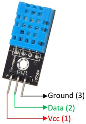
The DHT11 sensor is available either as a sensor or as a module. The only difference in them is that we need to manually add a filtering capacitor and a pull-up resistor to the sensor. If you have the sensor module, there is no need to add extra components as the sensor module will have them inbuilt. The sensor can measure from 0C to 50C and humidity from 20% to 90% with an accuracy of ±1°C and ±1%. When coming to the communication between the sensor and the microcontroller, the complete data transmission is 40 bit. The sensor sends higher data first. The data format for sending in the data is 8bit integral RH data +8bit RH data + *bit T data + 8bit decimal T data + 8bit checksum data. If the data transmission is right, the check-sum should be the last 8bit. The below fig shows the pinout of the DHT11 sensor. The sensor is very popular and we have previously used DHT11 in other, few of them are like Arduino Wireless Weather Station, IoT based Temperate and humidity monitoring, etc.
To make the programming easy, libraries are used. You can install DHT11 Arduino Library from the Arduino IDE. Open Arduino>Sketch>Include Library>Manage libraries and in the search button type DHT11. Install the libraries, which are given by Adafruit.
Interfacing DHT11 with NodeMCU ESP8266
As the DHT11 sensor is precalibrated in the laboratories, we don’t need to do any calibration for this sensor. Connect your DHT11 sensor with the NodeMCU as shown below.
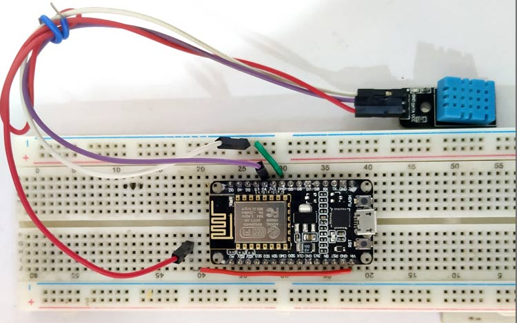
The VCC, GND, and Data pins are connected to the Vin, GND, and D4 pins of the microcontroller. By using Adafruit libraries for DHT11, we invoke the special function, which will fetch the temperature and humidity values. The format to use these functions are dht.readHumidity() and dht.readTemperature. These functions return the values of humidity and temperature. We declare variables h and t as floats and use them to store temperature and humidity values.
if (t > 23){
  digitalWrite(fan,HIGH);
}
else{
  digitalWrite(fan,LOW);
}
If the temperature is above the desired level, the microcontroller switches on the fan. If the temperature is lower than the desired valued it will switch off the fan
    if (isnan(h) || isnan(t)|| isnan(gas)) {
    Serial.println("Failed to read from DHT sensor!");
    }
}
Using ThingSpeak to Monitor Food Quality
To send the data to the cloud and display them on the web, we are going to use ThingSpeak. We have built many ThingSpeak Projects previously using it with Arduino and other boards like Raspberry Pi, ESP8266, etc. If you are new, you can also check this IoT Battery Monitoring, IoT Heartbeat Monitoring, IoT Inventory Management, etc where we used ThingSpeak.
Follow the steps below, to begin with, ThingSpeak
Step1: Sign up for ThingSpeak
For creating your channel on ThingSpeak, you first need to sign up on ThingSpeak. In case, if you already have an account on ThingSpeak just sign in using your id and password.
For creating your account go to www.thinspeak.com
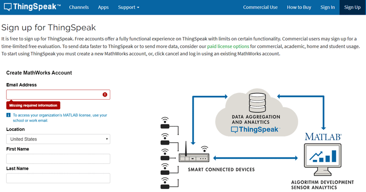
Verify your email ID and continue
Step-2: Create Your New Channel
To create your new channel. Select My channel>new channel.
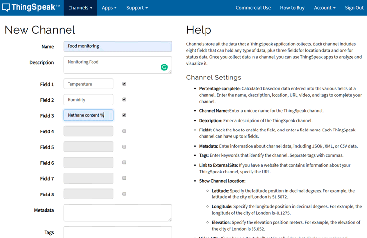
Enter the details and select save the channel.
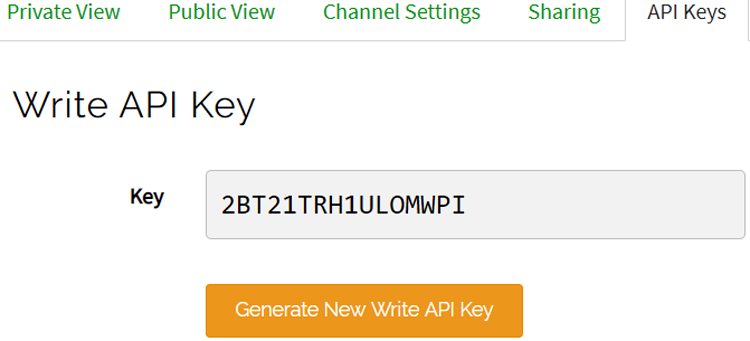
Step-3:- Get your API keys
After creating, open your channel and select the API keys options.
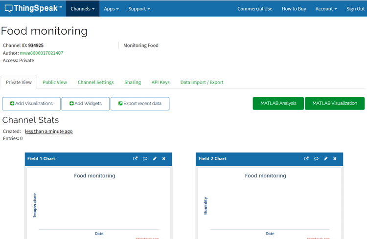
Note down the write API key. This unique key is used to send the data from the microcontroller to the web.
Program to send Sensor values to ThingSpeak
At first, you need to download all the required libraries.
#include <ESP8266WiFi.h>
#include <WiFiClient.h>;
#include <ThingSpeak.h>;
You can install these libraries from the Arduino IDE. Open Arduino>Sketch>Include Library>Manage libraries and in the search button type Thingspeak. Install the libraries, which are given by Mathworks.
const char * myWriteAPIKey = "YOUR_WRITE_API_KEY";.
unsigned long myChannelNumber = XXXXXX; //Replace it with your channel ID
const char* ssid = "YOUR_SSID ";
const char* password = "YOUR_SSID_PASSWORD";
const char* server = "api.thingspeak.com";
In the place, “YOUR_WRITE_API_KEY” write the API key which you noted down in step 3 and change the myChannelNumber with your channel ID. Replace the SSID and password with your network details.
float h = dht.readHumidity();
ThingSpeak.writeField(myChannelNumber, 2,h, myWriteAPIKey);
float t = dht.readTemperature();
ThingSpeak.writeField(myChannelNumber, 1,h, myWriteAPIKey);
The format for sending the data to the Thingspeak is
Thingspeak.writeField(myChannelNumber, FieldNumber,data_VARIABLE, myWriteAPIKey).
By using these commands, we can send real-time values to Thingspeak.
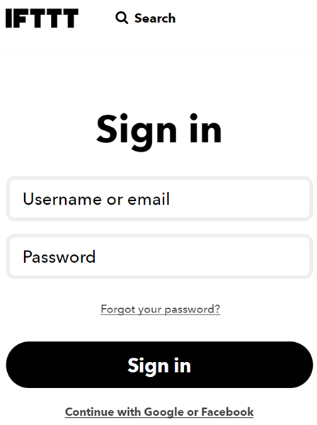
Send Email using IFTTT
To trigger an email, we first need to sign up for the IFTTT website https://ifttt.com/.
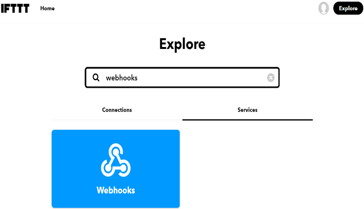
Select the search button and search for Webhooks and select Documentation.
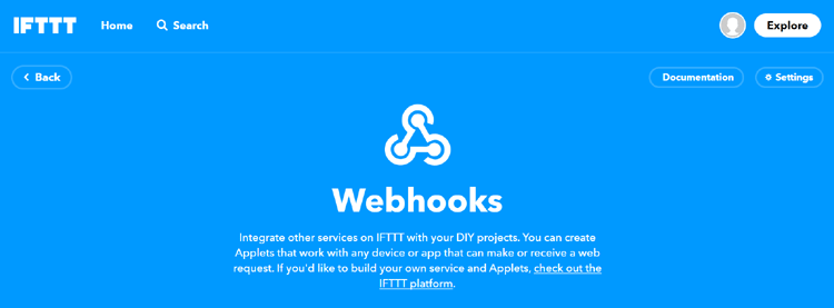
Copy the Private Key. Using this private key, you can trigger an email alert.
Program to send an Email using IFTTT
Our code will get triggered and sends us our warning email when the temperature value crosses the set value. You can change the set value for which the email triggering happens. The below code is used to form a TCP connection with the IFTTT server and create a URL for a request and sends that URL request to the server.
void send_event(const char *event)
{
Serial.print("Connecting to ");
Serial.println(host);
// Use WiFiClient class to create TCP connections
WiFiClient client;
const int httpPort = 80;
if (!client.connect(host, httpPort)) {
Serial.println("Connection failed");
return;
}
// This code is used to maintain a TCP connection with the IFTTT server.
String url = "/trigger/";
url += event;
url += "/with/key/";
url += privateKey;
Serial.print("Requesting URL: ");
Serial.println(url);
client.print(String("GET ") + url + " HTTP/1.1\r\n" +
"Host: " + host + "\r\n" +
"Connection: close\r\n\r\n");
while(client.connected())
{
if(client.available())
{
String line = client.readStringUntil('\r');
Serial.print(line);
} else {
delay(50);
};
}
Serial.println();
Serial.println("closing connection");
client.stop();
}
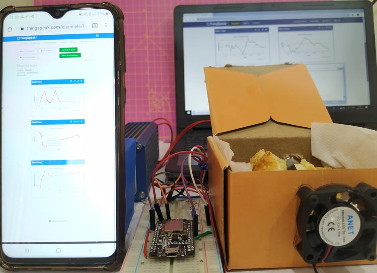
So this is how you can monitor the food quality. The temperature, humidity, and Methane value can be monitored by ThingSpeak from anywhere. If the parameters go abnormal, the fan will turn on automatically and the warning E-mail will also be triggered. The complete working can be found in the video below.
#include <DHT.h>
#include <ESP8266WiFi.h>
#include <WiFiClient.h>;
#include <ThingSpeak.h>;
#define RL 10.0 // the value of RL is 10K
#define m -0.36848 // using formula y = mx+c and the graph in the datasheet
#define c 1.105 // btained by before calculation
#define R0 1.9
#define fan D0 // pin for fan
// replace with your channel’s thingspeak API key,
const char * myWriteAPIKey = "YOUR_CHANNEL_API_CODE";
unsigned long myChannelNumber = YOUR_CHANNEL_ID; //Replace it with your channel ID
const char* ssid = "YOUR_SSID_POWER";
const char* password = "SSID_PASSWORD";
const char* server = "api.thingspeak.com";
const char *host = "maker.ifttt.com";
const char *privateKey = "YOUR_PRIVATE_KEY_FROM_IFTTT";
double gas;
#define Gas_Pin A0
#define DHTPIN D4 // CONNECT THE DHT11 SENSOR TO PIN D4 OF THE NODEMCU
DHT dht(DHTPIN, DHT11,15); //CHANGE DHT11 TO DHT22 IF YOU ARE USING DHT22
WiFiClient client;
void setup() {
Serial.begin(9600);
pinMode(fan,OUTPUT);
delay(10);
dht.begin();
ThingSpeak.begin(client);
WiFi.begin(ssid, password);
pinMode(Gas_Pin,INPUT);
Serial.println();
Serial.println();
Serial.print("Connecting to ");
Serial.println(ssid);
while (WiFi.status() != WL_CONNECTED) {
delay(200);
Serial.print(".");
}
Serial.println("");
Serial.println("WiFi connected");
}
int ppm1() {
float sensor_volt; //Define variable for sensor voltage
float RS_gas; //Define variable for sensor resistance
float ratio; //Define variable for ratio
float sensorValue = analogRead(Gas_Pin); //Read analog values of sensor
sensor_volt = sensorValue*(5.0/1023.0); //Convert analog values to voltage
RS_gas = ((5.0*10.0)/sensor_volt)-10.0; //Get value of RS in a gas
ratio = RS_gas/R0; // Get ratio RS_gas/RS_air
double ppm_log = (log10(ratio)-c)/m; //Get ppm value in linear scale according to the the ratio value
float ppm = pow(10, ppm_log); //Convert ppm value to log scale
Serial.println(ppm);
ThingSpeak.writeField(myChannelNumber, 3,ppm, myWriteAPIKey);
delay(200);
return(ppm);
}
void loop() {
float t = dht.readTemperature();
delay(200);
ThingSpeak.writeField(myChannelNumber, 1,t, myWriteAPIKey);
Serial.print("Temp = ");
Serial.println(t);
float h = dht.readHumidity();
delay(2000);
ThingSpeak.writeField(myChannelNumber, 2,h, myWriteAPIKey);
Serial.print("Humidity = ");
Serial.println(h);
gas = ppm1();
delay(2000);
if (t > 22){
digitalWrite(D0,HIGH);
send_event("temp_event");
Serial.println("Fan On");
}
else{
digitalWrite(fan,LOW);
}
if (isnan(h) || isnan(t)|| isnan(gas)) {
Serial.println("Failed to read from DHT sensor!");
}
}
void send_event(const char *event)
{
Serial.print("Connecting to ");
Serial.println(host);
// Use WiFiClient class to create TCP connections
WiFiClient client;
const int httpPort = 80;
if (!client.connect(host, httpPort)) {
Serial.println("Connection failed");
return;
}
// We now create a URI for the request
String url = "/trigger/";
url += event;
url += "/with/key/";
url += privateKey;
Serial.print("Requesting URL: ");
Serial.println(url);
// This will send the request to the server
client.print(String("GET ") + url + " HTTP/1.1\r\n" +
"Host: " + host + "\r\n" +
"Connection: close\r\n\r\n");
while(client.connected())
{
if(client.available())
{
String line = client.readStringUntil('\r');
Serial.print(line);
} else {
// No data yet, wait a bit
delay(50);
};
}
Serial.println();
Serial.println("closing connection");
client.stop();
}


