


If you have a pet in your home and you don’t have anyone to feed it when you are away from home then you definitely need some kind of machine to do this job. So here we are building a IoT Pet Feeder machine which is simple, efficient and cost effective. Using this machine you can feed your Pet by Google Assistant from anywhere in the world. You just have to say "Okay Google. Feed my pet" and rest of the things will be done by this machine. You can also set a specific time using Google Assistant to feed your Pet. For example Say "Okay Google. Feed my pet Today Morning" and it will feed your pet at previously specified time. Like this you can also set a specific time for noon and evening.
In this project, we are using a NodeMCU ESP8266 as the main controller, a Servo motor to open & close feeding bottle, and a 16*2 LCD to display the time. We will get the time from NTP servers. Instead of using RTC module for Time and Date, here we used NTP server to reduce the hardware components. NTP servers are better solution for getting time compare to RTC as it is more accurate and can provide the time of any geographical area in the world. Here is the complete tutorial on building a Internet time clock.
Components Required
- NodeMCU ESP8266
- 16x2 LCD Module
- LCD I2C Module
- Servo Motor
Circuit Diagram
Circuit diagram for this IOT based Pet Feeder project is given below. In this circuit diagram, a servo motor and LCD module is connected with NodeMCU ESP8266.
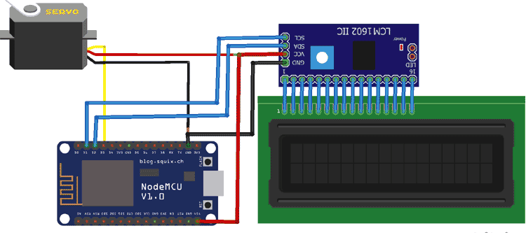
The Vcc & GND pin of Servo motor and LCD I2C module are connected with Vin & GND pin of NodeMCU. While SCL and SDA pins of I2C module is connected with D1 and D2 pin of NodeMCU respectively.
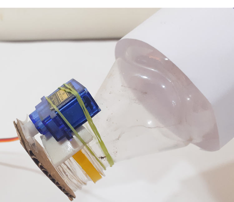
Here we have used a plastic bottle for the pet food container:
Adafruit IO Setup for IoT Pet Feeder
Adafruit IO is an open data platform that allows you to aggregate, visualize, and analyze live data on the cloud. Using Adafruit IO, you can upload, display, and monitor your data over the internet, and make your project IoT enabled. You can control motors, read sensor data, and make cool IoT applications over the internet using Adafruit IO. For test and try, with some limitation, Adafruit IO is free to use. We have also used Adafruit IO with Raspberry Pi previously.
1. For Adafruit IO setup, the first thing you will need to do is to sign up to Adafruit IO. To sign up go to Adafruit IO’s site https://io.adafruit.com and click on ‘Get started for Free’ on the top right of the screen.

2. After this, a window will pop up where you need to fill your details
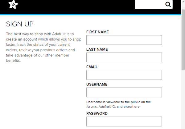
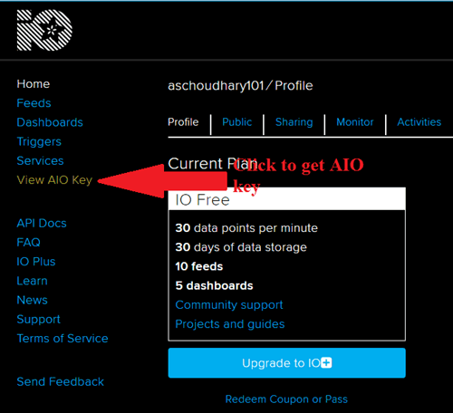
In sign up window fill your details like your name, mail id, username, etc. Then click on save settings, and your account is created. To get your AIO key click on ‘View AIO Key.’
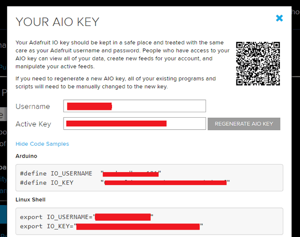
3. A window will pop up with your Adafruit IO AIO Key. Copy this key you'll need it later in your code.
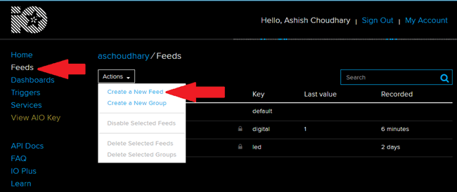
4. Now, after this, you need to create a feed. To create a feed click on ‘Feed.’ Then click on ‘Actions,’ you will see some options from them click on ‘Create a New Feed.’
5. After this a new window will open where you need to input:
Name – In name, option write a short descriptive name of your feed. You can use
Letters, numbers, and spaces.
Description - A long-form description of your data. This field is not required, but you
can write a description of your data.
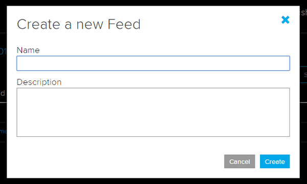
6. Click on ‘Create,’ you will then be redirected to your new feed.
IFTTT Setup for IoT Pet Feeder
IFTTT aka ‘If This Then That’ is a free web-based service to create chains of simple conditional statements, called applets. IFTTT allows users to create triggers and execute actions based on the triggers.
In this IoT cat feeder project, we are using IFTTT to create a trigger when we say a specific line using Google Assistant. For that we have to create an applet in which we will integrate the Google Assistant with Adafruit IO. We previously used Google assistant to build IoT projects.
First of all, create an account on IFTTT. To do so navigate to IFTTT website and click on signup. Then fill out the required details and click on create an account.
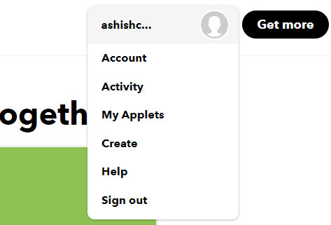
Now, as you are signed in to your account, click on your profile and then click on ‘Create.’
NOTE: Sign in to IFTTT using the same Email ID as used in your Android phone’s Google account. For example, if your phone is signed using the [email protected] Email ID, then sign in to IFTTT using the same Email ID.
Now create an applet using If ‘This’ Than ‘That.’ Here ‘This’ is the service name by which we will give input and ‘That’ will generate trigger according to input. So in this project we will use Google Assistant as ‘This’ and Adafruit IO as ‘That.’
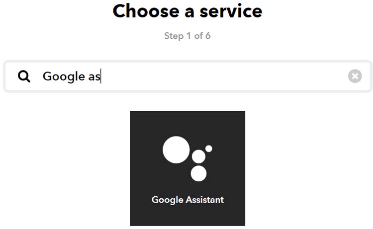
So to create an applet, click on the ‘This’ icon. And search for ‘Google Assistant.’ Here IFTTT will ask for permission for using your Google account.
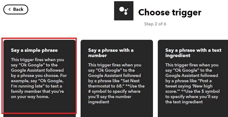
Now in Google Assistant click on ‘Say a simple phrase.’
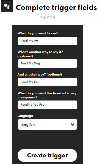
Now in the next window, it will ask you about the phrase that you want to say your Google Assistant and what you want to hear in response to that phrase. You can also add some optional phrases. Now click on Create Trigger.
Now one part of this applet is complete. For the second part click on the ‘That.’

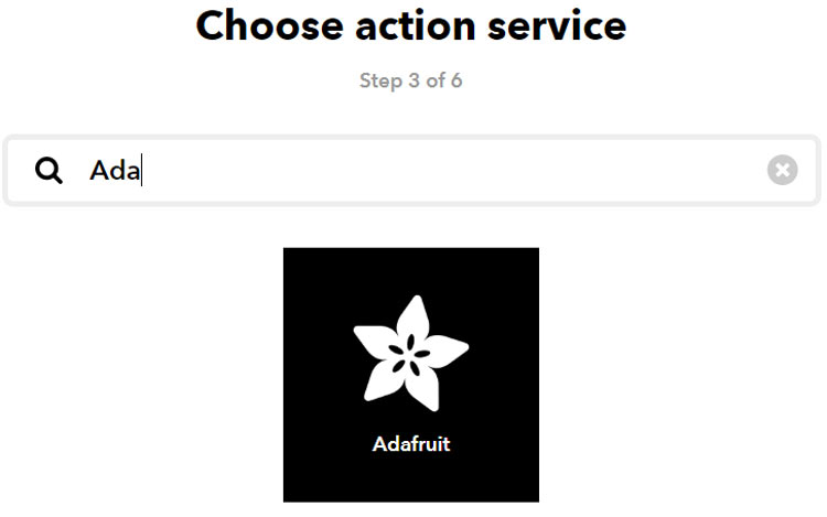
Now in the search window, search for ‘Adafruit’
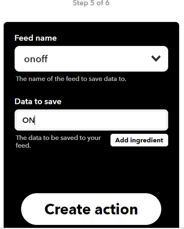
In the next window choose the feed name for which you want to create trigger and then enter the word/Data that you want to send to the feed when you say your specified phrase. After that click on ‘Create Action.’ After this it will ask you to finish the setup by clicking on the finish button. Now your applet is ready to use.
This applet was to feed the pet when we say a phrase to Google Assistant.
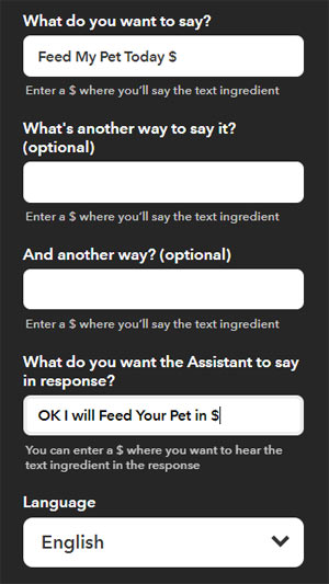
Now we will create another applet by which we can feed our pet at a specific time by saying a phrase with the text, for example, “Ok Google Feed My Pet Today Morning.” By using this applet we can send a trigger to ESP8266 at a specific time. For this applet follow the same steps: click on profile and then ‘Create.’ After that in ‘This’ option choose ‘Google assistant’. Now in google assistant click on ‘Say phrase with a Text ingredient’.
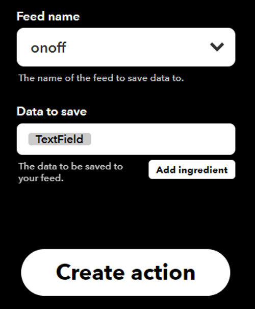
In the next window click on ‘That’ and choose Adafruit. In Adafruit select the same feed name as previous applet. Then click on ‘Create action’ and ‘Finish’ to finish the process
Code Explanation
Complete code for this Pet feeder along with a demonstration video is given at the end of this project, here we are explaining few parts of it.
Begin the code by including all the required libraries for this project. Arduino IDE has pre-installed libraries for servo motor and LCD module. But you have to download and install the rest of the libraries from the below given links:
#include <ESP8266WiFi.h>
#include "Adafruit_MQTT.h"
#include "Adafruit_MQTT_Client.h"
#include<Servo.h>
#include <NTPClient.h>
#include <WiFiUdp.h>
#include <LiquidCrystal_I2C.h>
#include <Wire.h>
To get accurate time from NTP server initialize the server location. Here I am using “pool.ntp.org” which is a pool of worldwide servers.
WiFiUDP ntpUDP;
NTPClient timeClient(ntpUDP, "pool.ntp.org", 19800,60000);
Here in this part of code, we are defining the Adafruit server address, port number, Adafruit account username and unique AIO key that you copied from your Adafruit account. This is used to establish the MQTT connection between ESP and Adafruit IO.
#define MQTT_SERV "io.adafruit.com"
#define MQTT_PORT 1883
#define MQTT_NAME "Username"
#define MQTT_PASS "AIO Key"
In this part of code, set up the MQTT and WiFi clients using previous information, i.e. adafruit username, AIO key, server address, and port no.
WiFiClient client;
Adafruit_MQTT_Client mqtt(&client, MQTT_SERV, MQTT_PORT, MQTT_NAME, MQTT_PASS);
Now here we set up the feed with a name “onoff” and subscribing to it.
Adafruit_MQTT_Subscribe onoff = Adafruit_MQTT_Subscribe(&mqtt, MQTT_NAME "/f/onoff");
timeClient.begin(); function is used to start the NTP client so the it can send data to ESP8266.
timeClient.begin();
Inside the void loop, timeClient.update() function is used to update the date and time whenever we request to NTP servers. After getting the data, we store the hour, minute and second in three different integers.
timeClient.update();
hh = timeClient.getHours();
mm = timeClient.getMinutes();
ss = timeClient.getSeconds();
Here we are directly checking for a specific word in our subscribed feed and if the word matches with our specified word, i.e. ‘ON’ it will call the open_door() and close_door() function.
      if (!strcmp((char*) onoff.lastread, "ON"))
      {
        open_door();
        delay(1000);
        close_door();
       }
By using the if condition assign a specific time to the “Morning”, “Afternoon” and “Evening” strings. After that use another if condition to match the current time and feed time. So whenever we say “Feed My Pet Today Morning” it will call the open_door() and close_door() function when the current time is equal to 10:30. It will follow the same procedure for “Evening” and “Afternoon” strings.
if (!strcmp((char*) onoff.lastread, "Morning"))
      {
        feed_hour = 10;
        feed_minute = 30;
      }
     }
   }
   if( hh == feed_hour && mm == feed_minute &&feed==true) //Comparing the current time with the Alarm time
    {
      open_door();
      delay(1000);
      close_door();
      feed= false;
      }
}
void open_door() and void close_door() function are used to send the command to the servo motor to open the trap door. Open angle is defined as 60° while the close angle is defined as 0°.
void open_door(){
    servo.write(OPEN_ANGLE)
void close_door(){
    servo.write(CLOSE_ANGLE);
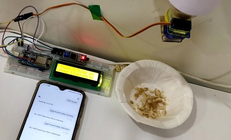
Working of the IoT Pet Feeder
After uploading the code to the NodeMCU, the current time and Feed time will be displayed on the 16*2 LCD. Initially, it will show 0:0 in feed time as we didn’t enter any feed time. Now Say "Okay Google. Feed my pet" to your Google Assistant. Google Assistant will recognize the phrase and respond with "Feeding your pet." After that it rotates the servo motor from its initial position 0⁰ to 60⁰ and after a delay, it returns to its initial position. You can also feed your pet at a specific time. For that we have used three strings i.e., “Morning”, “Afternoon” and “Evening”. These strings are assigned with different times, so when you say “Feed My Pet Today Morning” it will take the time assigned to “Morning” string as feeding time and when the entered time matches with current time it rotates the servo motor from its initial position 0⁰ to 60⁰ and after a delay it returns to its initial position.
This is how you can feed your pet using Google Assistant. If you want to feed your pet at a specific time instead of morning, afternoon and evening, go to IFTTT and change the Google assistant settings from ‘Say a phrase with text ingredient’ to ‘Say a phrase with a number’.
Complete process is shown in the video given below.
#include <ESP8266WiFi.h>
#include "Adafruit_MQTT.h"
#include "Adafruit_MQTT_Client.h"
#include<Servo.h>
#include <NTPClient.h>
#include <WiFiUdp.h>
#include <LiquidCrystal_I2C.h>
#include <Wire.h>
WiFiUDP ntpUDP;
NTPClient timeClient(ntpUDP, "pool.ntp.org", 19800,60000);
Servo servo;
LiquidCrystal_I2C lcd(0x27, 16, 2);
#define WIFI_SSID "Galaxy-M20"
#define WIFI_PASS "ac312124"
#define MQTT_SERV "io.adafruit.com"
#define MQTT_PORT 1883
#define MQTT_NAME "aschoudhary"
#define MQTT_PASS "1ac95cb8580b4271bbb6d9f75d0668f1"
int SERVO_PIN = D3; // The pin which the servo is attached to
int CLOSE_ANGLE = 0; // The closing angle of the servo motor arm
int OPEN_ANGLE = 60; // The opening angle of the servo motor arm
int hh, mm, ss;
int feed_hour = 0;
int feed_minute = 0;
//Set up MQTT and WiFi clients
WiFiClient client;
Adafruit_MQTT_Client mqtt(&client, MQTT_SERV, MQTT_PORT, MQTT_NAME, MQTT_PASS);
//Set up the feed you're subscribing to
Adafruit_MQTT_Subscribe onoff = Adafruit_MQTT_Subscribe(&mqtt, MQTT_NAME "/f/onoff");
boolean feed = true; // condition for alarm
void setup()
{
Serial.begin(9600);
timeClient.begin();
Wire.begin(D2, D1);
lcd.begin();
//Connect to WiFi
Serial.print("\n\nConnecting Wifi... ");
WiFi.begin(WIFI_SSID, WIFI_PASS);
while (WiFi.status() != WL_CONNECTED)
{
delay(500);
}
Serial.println("OK!");
//Subscribe to the onoff feed
mqtt.subscribe(&onoff);
servo.attach(SERVO_PIN);
servo.write(CLOSE_ANGLE);
}
void loop()
{
MQTT_connect();
timeClient.update();
hh = timeClient.getHours();
mm = timeClient.getMinutes();
ss = timeClient.getSeconds();
lcd.setCursor(0,0);
lcd.print("Time:");
if(hh>12)
{
hh=hh-12;
lcd.print(hh);
lcd.print(":");
lcd.print(mm);
lcd.print(":");
lcd.print(ss);
lcd.println(" PM ");
}
else
{
lcd.print(hh);
lcd.print(":");
lcd.print(mm);
lcd.print(":");
lcd.print(ss);
lcd.println(" AM ");
}
lcd.setCursor(0,1);
lcd.print("Feed Time:");
lcd.print(feed_hour);
lcd.print(':');
lcd.print(feed_minute );
Adafruit_MQTT_Subscribe * subscription;
while ((subscription = mqtt.readSubscription(5000)))
{
if (subscription == &onoff)
{
//Print the new value to the serial monitor
Serial.println((char*) onoff.lastread);
if (!strcmp((char*) onoff.lastread, "ON"))
{
open_door();
delay(1000);
close_door();
}
if (!strcmp((char*) onoff.lastread, "Morning"))
{
feed_hour = 10;
feed_minute = 30;
}
if (!strcmp((char*) onoff.lastread, "Afternoon"))
{
feed_hour = 1;
feed_minute = 30;
}
if (!strcmp((char*) onoff.lastread, "Evening"))
{
feed_hour = 6;
feed_minute = 30;
}
}
}
if( hh == feed_hour && mm == feed_minute &&feed==true) //Comparing the current time with the Feed time
{
open_door();
delay(1000);
close_door();
feed= false;
}
}
void MQTT_connect()
{
int8_t ret;
// Stop if already connected.
if (mqtt.connected())
{
return;
}
uint8_t retries = 3;
while ((ret = mqtt.connect()) != 0) // connect will return 0 for connected
{
mqtt.disconnect();
delay(5000); // wait 5 seconds
retries--;
if (retries == 0)
{
// basically die and wait for WDT to reset me
while (1);
}
}
}
void open_door(){
servo.write(OPEN_ANGLE); // Send the command to the servo motor to open the trap door
}
void close_door(){
servo.write(CLOSE_ANGLE); // Send te command to the servo motor to close the trap door
}


