


From connected cars to connected wearables to home security, the Internet of Things is rapidly marking its presence in every field. Now we have IoT enabled home automation and security devices that can be controlled from anywhere in the world using the Internet of Things. There are many kinds of Wi-Fi door lock available in the market which makes your home more secure and saves time in finding the keys. Here we are also building a similar Wi-Fi door lock which can be controlled from the Smartphone.
So in this project, we are going to make an IOT based Door Lock System using NodeMCU, Solenoid Lock, and Adafruit IO. Here NodeMCU will act as the main controller and connect the user to the door lock system using the Internet. This allows the user to lock/unlock his Home’s door lock by using a smartphone from anywhere in the world. If you are looking for something simple you can also check out how to build a simple door lock system using Arduino.
Components Required
- NodeMCU ESP8266
- Solenoid Lock
- Relay Module
- Buzzer
We have used NodeMCU ESP8266 in many of our previous IoT projects, here we are using a Solenoid Door lock with it, so let's learn about this electronic door lock first.
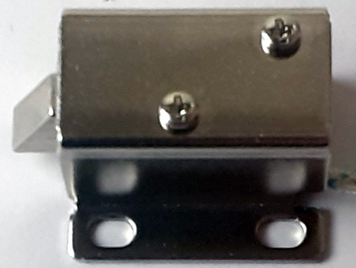
Solenoid Lock
In conventional door lock, there is key to pull or push the latch, and we have to operate it manually, but in solenoid lock, the latch can be operated automatically by applying a voltage. Solenoid lock has a low-voltage solenoid that pulls the latch back into the door when an interrupt (Pushbutton, Relay, etc.) is activated. The latch will retain its position until the interrupt is enabled. The operating voltage for the solenoid lock is 12V. You can also use 9V, but it results in slower operation. Solenoid door locks are mainly used in remote areas to automate operations without involving any human effort.
Smart Door Lock Circuit Diagram
The circuit diagram for the Wi-Fi door lock is given below.
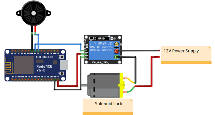
Connections for this IoT Smart Door Lock are very simple as we are only connecting a solenoid lock, relay module, and a buzzer with NodeMCU ESP8266. The input pin of the relay is connected to the D5 pin of NodeMCU while VCC and Ground pins are connected to Vin and GND pin of NodeMCU. The positive pin of the buzzer is connected to the D6 pin of NodeMCU, and the GND pin is connected to the GND of NodeMCU.
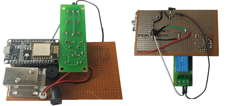
I have soldered all the components on Perfboard as shown in the below pictures:
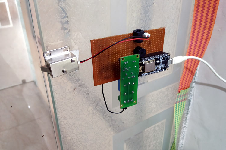
This is how the complete setup of wifi door lock will look after installing on the door:
Adafruit IO Setup for IoT Door Lock
Adafruit IO is an open data platform that allows you to aggregate, visualize, and analyze live data on the cloud. Using Adafruit IO, you can upload, display, and monitor your data over the internet, and make your project IoT enabled. You can control motors, read sensor data, and make cool IoT applications over the internet using Adafruit IO. For test and try, with some limitation, Adafruit IO is free to use. We have also used Adafruit IO with Raspberry Pi, Arduino and ESP32 previously.
1. To use Adafruit IO, first, you have to create an account on Adafruit IO. To do this, go to the Adafruit IO website and click on ‘Get started for Free’ on the top right of the screen.

2. After finishing the account creation process, log in to your account and click on ‘AIO Key’ on the top right corner to get your account username and AIO key.
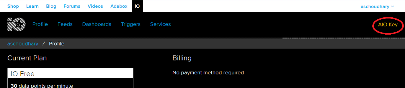
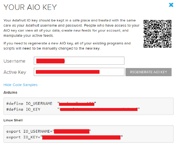
When you click on ‘AIO Key,’ a window will pop up with your Adafruit IO AIO Key and username. Copy this key and username, it will be needed later in the code.
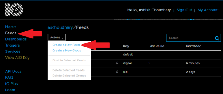
3. Now, after this, you need to create a feed. To create a feed, click on ‘Feed.’ Then click on ‘Actions,’ and then click on ‘Create a New Feed’ as shown in the image below.
4. After this, a new window will open to enter the Name and Description of the feed. The writing description is optional.
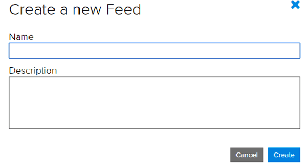
5. Click on ‘Create,’ after this; you will be redirected to your newly created feed.
After creating the feed, now create an Adafruit IO dashboard to add a toggle button to open and close the door lock. For that, first, create a dashboard and then add your feed in this dashboard.
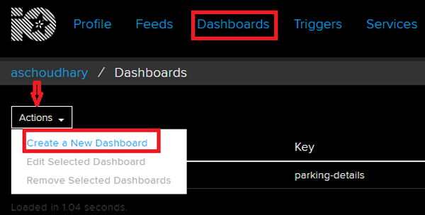
To create a dashboard, click on the Dashboard option and then click on the ‘Action,’ and after this, click on ‘Create a New Dashboard.’
In the next window, enter the name for your dashboard and click on ‘Create.’
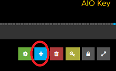
6. As the dashboard is created, now, we will add our feeds to the dashboard. To add a feed, click on the ‘+’ in the top right corner.
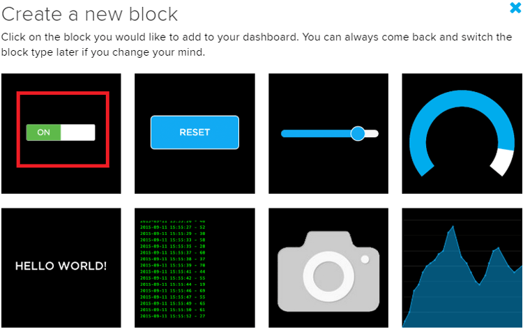
Here we will add a toggle button blocks to turn open and close the Wi-Fi door lock. To add a button on the dashboard, click on the Toggle block.
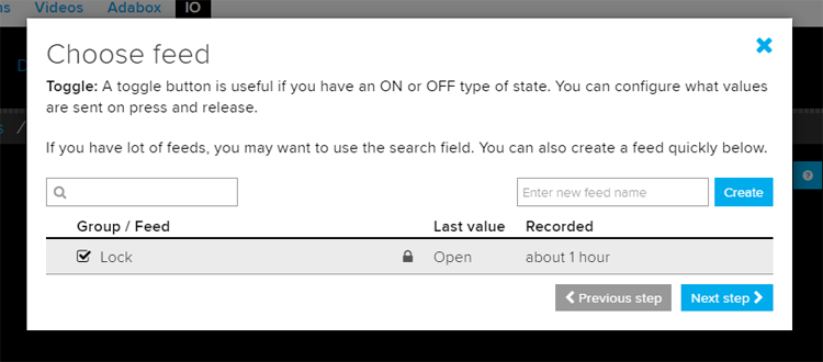
In the next window, it will ask you to choose the feed, so click on your feed.
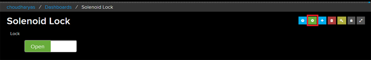
After adding the toggle button, my dashboard looks like below. You can edit the dashboard by clicking on the settings buttons.
Code Explanation
Complete code with a working video for this smart door lock using IOT is given at the end of the document. A detailed explanation of the code is given below.
First, include all the required libraries. In this program, only Adafruit MQTT and ESP8266WiFi.h libraries are used. You can download the Adafruit library by following this link.
Then include the WiFi and Adafruit IO credentials that you copied from the Adafruit IO server. These will include the MQTT server, Port No, User Name, and AIO Key
const char *ssid =  "Wi-Fi Name";     // Enter your WiFi Name
const char *pass =  "Password"; // Enter your WiFi Password
#define MQTT_SERV "io.adafruit.com"
#define MQTT_PORT 1883
#define MQTT_NAME "Adafruit IO Username"
#define MQTT_PASS "Your API Ley"
Then set up an MQTT connection using the credentials that you provided earlier.
Adafruit_MQTT_Client mqtt(&client, MQTT_SERV, MQTT_PORT, MQTT_NAME, MQTT_PASS);
Set up the feeds you're subscribing to. Here ‘Lock’ is the Feed name.
Adafruit_MQTT_Subscribe Lock = Adafruit_MQTT_Subscribe(&mqtt, MQTT_NAME "/f/Lock");
Inside the void setup function, define the buzzer pin and relay pin as an output.
pinMode(relay, OUTPUT);
pinMode(buzzer, OUTPUT);
Now, the void loop function will continuously check your subscribed feed for data, and it will compare that data with the defined string. If the received and defined string both are the same, then it will perform further operations according to the data.
Adafruit_MQTT_Subscribe * subscription;
while ((subscription = mqtt.readSubscription(5000)))
     {
   if (subscription == &Lock)
     {
      //Print the new value to the serial monitor
      Serial.println((char*) Lock.lastread);
   if (!strcmp((char*) Lock.lastread, "Close"))
      {
        digitalWrite(relay, LOW);
        Serial.print("Door Unlocked");
        digitalWrite(buzzer, HIGH);
        delay(2000);
        digitalWrite(buzzer, LOW);
    }
    if (!strcmp((char*) Lock.lastread, "Open"))
      {
        digitalWrite(relay, HIGH);
        Serial.print("Door Closed");
        digitalWrite(buzzer, HIGH);
        delay(2000);
        digitalWrite(buzzer, LOW);
    }
Testing the IoT based Door Lock System
Once the hardware and code are ready, connect the NodeMCU to your laptop and upload the code. After that, open the Adafruit IO dashboard and toggle the button to open and close the gate.
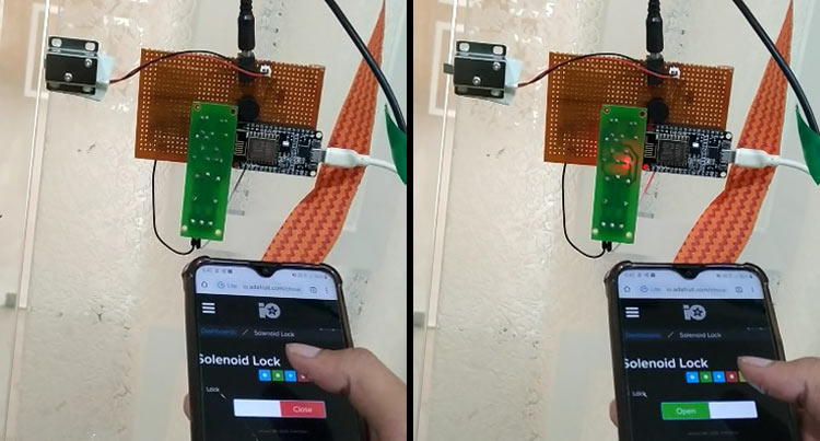
A complete working video and full code are given below.
#include <ESP8266WiFi.h>
#include "Adafruit_MQTT.h"
#include "Adafruit_MQTT_Client.h"
const char *ssid = "Wi-Fi Name"; // Enter your WiFi Name
const char *pass = "Password"; // Enter your WiFi Password
WiFiClient client;
#define MQTT_SERV "io.adafruit.com"
#define MQTT_PORT 1883
#define MQTT_NAME "Adafruit IO Username"
#define MQTT_PASS "Your API Key" // Enter the API key that you copied from your adafrui IO account
#define relay D5
#define buzzer D6
Adafruit_MQTT_Client mqtt(&client, MQTT_SERV, MQTT_PORT, MQTT_NAME, MQTT_PASS);
//Set up the feed you're subscribing to
Adafruit_MQTT_Subscribe Lock = Adafruit_MQTT_Subscribe(&mqtt, MQTT_NAME "/f/Lock");
void setup()
{
Serial.begin(115200);
delay(10);
mqtt.subscribe(&Lock);
pinMode(relay, OUTPUT);
pinMode(buzzer, OUTPUT);
digitalWrite(relay, LOW); // keep motor off initally
Serial.println("Connecting to ");
Serial.println(ssid);
WiFi.begin(ssid, pass);
while (WiFi.status() != WL_CONNECTED)
{
delay(500);
Serial.print("."); // print ... till not connected
}
Serial.println("");
Serial.println("WiFi connected");
}
void loop()
{
MQTT_connect();
Adafruit_MQTT_Subscribe * subscription;
while ((subscription = mqtt.readSubscription(5000)))
{
if (subscription == &Lock)
{
//Print the new value to the serial monitor
Serial.println((char*) Lock.lastread);
if (!strcmp((char*) Lock.lastread, "Close"))
{
digitalWrite(relay, LOW);
Serial.print("Door Unlocked");
digitalWrite(buzzer, HIGH);
delay(2000);
digitalWrite(buzzer, LOW);
}
if (!strcmp((char*) Lock.lastread, "Open"))
{
digitalWrite(relay, HIGH);
Serial.print("Door Closed");
digitalWrite(buzzer, HIGH);
delay(2000);
digitalWrite(buzzer, LOW);
}
}
}
}
void MQTT_connect()
{
int8_t ret;
// Stop if already connected.
if (mqtt.connected())
{
return;
}
uint8_t retries = 3;
while ((ret = mqtt.connect()) != 0) // connect will return 0 for connected
{
mqtt.disconnect();
delay(5000); // wait 5 seconds
retries--;
if (retries == 0)
{
// basically die and wait for WDT to reset me
while (1);
}
}
}


